
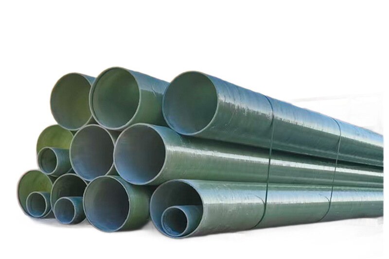
A chimney or stack is the most corrosive part of many plants — and often the least inspected. Hot exhaust gas cools as it rises, and the moment it drops below the acid dew point, condensation forms on the wall: sulfuric and hydrochloric acids from combustion or process gases, absorbed into condensed water, eating steel and spalling concrete from the inside out. An FRP flue or chimney liner stops that attack at the source.
This guide covers how to specify an FRP flue liner correctly — the two operating zones that decide the design, resin and temperature limits, insulation strategy, connections, and the data your supplier needs for a quotation.
1. The Two Zones of Every Flue
- Dry zone (hot section) — gas stays above its dew point; the wall sees heat and gas velocity but little condensation. The risk here is thermal, not chemical.
- Wet zone (upper section / cold start) — gas cools below the dew point; acid condenses on the wall and runs down. This zone decides the corrosion barrier design.
Every stack cycles through both zones during start-up and load changes, so the liner must handle condensation even if the design point is "dry".
2. Materials: Resin, Reinforcement, Barrier
| Exhaust duty | Recommended resin | Typical temperature ceiling |
|---|---|---|
| Flue gas, mild acidity, low SOx | Isophthalic polyester | ~80–90 °C continuous |
| Higher acids, wet/dry cycling, condensation | Vinyl ester | ~110–130 °C by grade |
| Severe acid + high temperature | Novolac vinyl ester | ~180–200 °C by grade |
The corrosion barrier on the gas side uses a resin-rich liner with C-glass or carbon veil — carbon veil adds conductivity where static and lightning dissipation matter. Confirm the actual continuous and peak gas temperatures, because they, not the pipe diameter, select the resin.
3. Insulation: Keep the Gas Above the Dew Point
Insulation on a flue liner serves two masters:
- Process: keeping flue gas hot preserves buoyancy (draft) and prevents premature condensation.
- Protection: limiting the liner wall temperature so the laminate stays inside its resin rating.
Typical practice for an FRP liner inside an existing steel or concrete stack is to insulate the annulus between liner and shell, supporting the liner on a bearing plate at the base with a sliding support near the top to allow thermal growth.
4. Pressure, Velocity and Diameter
Flues mostly run under slight negative pressure (induced draft) or positive pressure (forced draft). Two consequences:
- Negative draft: the liner must resist external buckling from the annulus wind load and from partial vacuum — ring stiffness and stiffening rings matter more than pressure rating.
- Positive pressure: the liner and every joint become a pressure boundary; specify a pressure class and test joints accordingly.
Gas velocity typically sits between 10 and 25 m/s for process stacks; higher velocity increases erosion if condensate droplets are entrained, so specify velocity and any particulate content with the enquiry.
5. Connections, Expansion and Details
- Thermal movement: FRP expands more than steel; an FRP liner in a long steel stack needs a slip joint or expansion joint near the top so vertical growth is not restrained.
- Support lugs transmit the liner weight to the stack shell without point-loading the laminate — use a full bearing ring at the base.
- Entry ports for inspection and cleaning must be flanged with the same resin system and sealed against the gas side.
- Lightning and static: in tall stacks specify conductive carbon veil plus an earth path, and bond liner sections together.
6. Retrofitting an FRP Liner Into an Existing Stack
The most common application is a new FRP liner dropped inside a corroded steel or concrete chimney, avoiding demolition:
- Survey the existing shell, and confirm access and lifting constraints for liner sections (often 6–12 m, field-jointed inside the stack).
- Design the annulus insulation and the base bearing arrangement.
- Install and field-joint with butt-and-wrap or flanged connections, then spark-test the completed liner for pinholes before commissioning.
7. Specification Checklist
| Data point | Why it is needed |
|---|---|
| Gas composition incl. SOx/HCl and particulates | Selects resin and veil |
| Continuous and peak gas temperature | Selects resin class |
| Acid dew point / operating load range | Defines the wet zone and insulation duty |
| Pressure (draft) regime | Sets stiffness or pressure class |
| Stack height, diameter and wind loads | Structural design of liner and supports |
8. Common Specification Mistakes
- Rating the liner on peak temperature but a resin that cannot survive the wet condensation chemistry.
- Forgetting insulation, so gas condenses a few metres above the inlet.
- Rigidly fixing a long liner and letting thermal growth buckle it.
- Testing only the pipe, not the field joints, before the stack is put back in service.
Our FRP flues and stack liners are wound in vinyl ester or novolac grades with conductive veil options; for fume ducting on the low-temperature side, see FRP ventilation ducts, and browse the pipes & fittings range for matching connections.
Need help selecting FRP products?
Our engineers answer technical questions free of charge.
Ask an Engineer on WhatsApp