
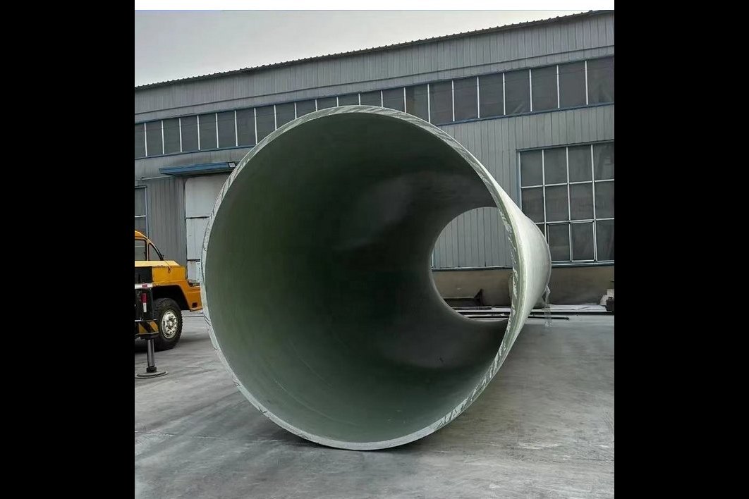
A forklift tine, an excavator bucket, a dropped scaffold tube — most GRP pipeline damage in service is mechanical, sudden and localized, and most of it gets repaired in the field rather than at the factory. The engineering question is never "can we patch it?" — with a resin bucket and some cloth you almost always can — but "what class of repair restores this pipe's pressure capability, who is qualified to apply it, and what evidence will the owner accept?" Unlike steel, a fiberglass pipe cannot be welded, and the laminate damage around a visible impact point frequently extends well beyond what the surface shows. This guide works through the decision framework, the three repair families (clamps, laminated overwraps and section replacement), the ISO 24817 and ISO 14692-4 requirements that govern each, and a fully worked DN400 example.
1. Why GRP Damage Needs Its Own Playbook
Fiberglass pipe fails differently from steel. Where a corroded steel wall thins predictably and can be measured with UT, an impact on GRP can initiate interlaminar delamination that spreads far past the visible scar while the outer surface stays intact. This is exactly the concern ISO 24817 — the composite repair standard written primarily for steel substrates — flags when its scope touches fiberglass: the standard's own text notes that pipework substrates it covers include GRP, and warns that before repairing GRP lines, "careful consideration is required... because the damage in the pipe may be more extensive than is visible on the surface and may affect a longer length of the pipe than is immediately obvious," and that the advice of the GRP pipe manufacturer and repair system supplier shall be sought before a repair is installed.
The structural framework for the pipe itself is ISO 14692, the GRP piping standard for the petroleum and natural gas industries. Part 4 (fabrication, installation and operation) explicitly covers maintenance and repair, with clause structures for repair after installation that distinguish between replacement of a damaged section, minor repairs and temporary repairs, all executed under a documented repair quality programme by trained and certified installers and inspectors. Practically, that means two things for an asset owner: first, repairs are expected to be planned work with defined methods and trained personnel — not improvised maintenance; second, the manufacturer's repair procedure for the specific pipe system is the baseline document, because adhesive, resin, cure schedule and laminate build-up are all system-specific.
2. Classify the Damage Before Choosing a Method
The first field task is a damage survey, not a repair. For a DN100–DN200 pipe you can often trace damage with a coin tap: a sound laminate rings, a delaminated area gives a dull thud, and the change in tone maps the true extent of the debonded zone. For larger diameters or critical service, add visual inspection of the bore through the nearest access points (a through-wall leak always shows on the inside first), Barcol hardness readings to confirm the parent laminate is fully cured, and — where the pipe carries hydrocarbons or aggressive chemicals — a longer section survey, because longitudinal cracking tends to follow the winding angle and can run metres from the impact point.
Sort every finding into one of five classes, because each class maps to a different repair family:
- Class A — cosmetic: gelcoat scratch or resin-rich layer scuff with no fibre damage and no pressure consequence. Clean and re-coat with gelcoat or liner resin.
- Class B — surface abrasion: structural wall reduced locally but no leak path, no delamination beyond the abraded area. Ground, then rebuild with overwound laminate to restore wall thickness.
- Class C — external structural damage: impact crater, gouge or cracking with fibre breakage but wall still watertight. Laminated overwrap repair after grinding out the defect.
- Class D — through-wall leak: pinhole, slot or shattered patch, fluid escaping. Clamp for immediate stop-leak, then overwrap or section replacement for the permanent fix.
- Class E — joint or fitting failure: leaking adhesive joint, cracked coupling band or damaged flange. Usually a joint redo or spool replacement — never a wrap over a failed joint, which hides the root cause.
The most expensive mistake in GRP pipe repair is wrapping a Class D leak without first mapping it as such. The overwrap stops the drip, the delamination keeps growing under the laminate, and six months later the repair fails with nobody able to see why.
3. The Three Repair Families Compared
Each family answers a different question: how fast must the line return to service, and what pressure capability must be restored?
| Criterion | Repair clamp | Laminated overwrap | Section replacement |
|---|---|---|---|
| Time to stop a leak | 30–90 min | 4–8 h (incl. cure) | 1–3 days |
| Pressure capability restored | Partial; per clamp maker rating | Full design pressure (designed per ISO 24817) | Full original rating |
| Expected service life | Temporary to medium-term | Designable to the repair lifetime (ISO 24817 allows up to 50 years) | Same as original pipe |
| Skill required | Fitter with torque wrench | Certified laminator, trained per ISO 14692-4 | Certified jointing crew |
| Best for | Class D emergency stop-leak | Class B/C permanent restoration; Class D after mapping | Class E, extensive Class D, delamination > one pipe diameter |
| Key risk | Over-torque dents GRP; clamp becomes permanent | Poor surface prep; hidden delamination left in place | Misalignment; coupling not axially restrained |
Clamps and overwraps are not competitors — on a leaking line the clamp buys the time to do the overwrap properly. What matters is that nobody mistakes the clamp for the finished repair.
4. Repair Clamps on GRP: Wide Bands, Gentle Torque, Gasket Relaxation
A repair clamp is a fabricated steel band with an integral elastomer gasket, bridged over the damage. On fiberglass pipe three details decide whether the clamp helps or harms. First, the band must be wide — manufacturer installation instructions for full-circle clamps typically call for the clamp to extend well past the damage, and where a section of wall is missing entirely, a backing surface (sheet metal strip) is required under the gasket, with the clamp extending beyond it axially. As a field rule of thumb for a slot defect, size the band to cover roughly twice the defect length plus 150 mm each side — for the 120 mm slot in our worked example, that means a band of at least 540 mm.
Second, torque discipline. Published clamp instructions give manufacturer-specific values — one widely used full-circle clamp line specifies 50 ft·lb (68 N·m) through about 120 mm OD and 70 ft·lb (95 N·m) above that; another maker recommends 135 N·m with a calibrated wrench. The number itself matters less than the discipline: GRP does not tolerate the localized denting that a steel main absorbs, so never exceed the clamp maker's printed torque and never "fix" a leak by adding torque beyond it. Third, gasket relaxation: elastomer creeps under compression, so instructions commonly require a re-torque at least 30 minutes after initial tightening — repeated once more after a couple of hours if the line stays out of service overnight.
Record the clamp as a temporary repair with a defined follow-up action. ISO 14692-4's repair structure keeps temporary repairs in a separate category precisely so they are tracked and closed out; a clamp that is still on the line five years later with no inspection record is an audit finding waiting to happen.
5. Laminated Overwrap Repair: ISO 24817 Applied to a GRP Substrate
The permanent repair for Classes B, C and mapped D damage is a laminated overwrap — glass fibre reinforcement wetted with a resin matched to the pipe system, built up around the damage and cured in place. ISO 24817 provides the design machinery; although written for the petrochemical industry, it is the reference its own bibliography pairs with GRP piping practice, and its qualification and design chapters are the ones owner specifications increasingly cite for composite repairs regardless of substrate.
The design distinguishes Type A defects (wall loss or external damage; the wall still contains the pressure) from Type B defects (through-wall leaks, where filler fills the hole and the laminate must carry load). For a Type A repair, the minimum repair thickness follows from a strain-based hoop check on the same logic used in the PPIM/pipeline practice literature:
tmin = D · (P − Ps) / (2 · εc · Ec)
where D is the pipe outside diameter, P the design pressure, Ps the pressure the remaining (undamaged) pipe wall can still carry, εc the allowable repair-laminate strain and Ec its tensile modulus. ISO 24817 additionally caps what repair systems may be asked to do (its qualification limits wall loss to about 85–90% and ties the allowable strain to tested, degraded laminate properties), and requires a minimum of two plies — a floor ASME PCC-2, the US counterpart standard, states explicitly for composite repairs.
Axial extent is where field crews most often undershoot. ISO 24817 section 7.5.8 requires the design thickness to extend beyond the damaged region by the larger of 50 mm or lover, where for a slot-type defect lover = 2√(D·t) and for a circular defect lover = 4d (with d the defect diameter, applicable when d < 0.5√(D·t)). The total repair length is then l = 2·lover + ldefect + 2·ltaper, and laminate ends must be tapered at approximately 5:1 where axial loads exist. Surface preparation follows the same discipline as any structural laminate joint: grind back to sound, dry, abraded GRP around the full repair area, chamfer the damage edge, solvent-clean, and lay up plies working from the centre outward, rolling out entrapped air as you go. The resin must match the pipe's corrosion barrier chemistry — a vinyl ester repair on an isophthalic polyester pipe is a chemistry decision the manufacturer signs off, not a site improvisation.
6. Worked Example: DN400 PN6 Pipe With a 120 mm Slot
Consider a DN400 filament-wound GRP process line at PN6, with a 426 mm outer diameter and 6.4 mm wall, damaged by an excavator tooth that left a 120 mm axial slot. The line is shut down and drained for the repair. First, confirm the intact wall is comfortable at design pressure:
| Step | Quantity | Value |
|---|---|---|
| Intact-wall check | Hoop stress at 0.6 MPa (Barlow, OD form) | 19.7 MPa |
| Hoop strain at Epipe = 11,000 MPa | 0.179% (< 0.25% long-term limit) | |
| Repair extent (slot defect) | lover = 2√(D·t) | 104 mm (> 50 mm floor) |
| Repair thickness | tmin = D·P/(2·εc·Ec), εc = 0.20%, Ec = 18,000 MPa | 3.55 mm → 4 plies × 0.9 mm |
| End taper | 5:1 on 3.6 mm design thickness | 18 mm each end |
| Total repair length | 2·lover + ldefect + 2·ltaper | 365 mm |
| Repair laminate check | Strain in repair at full design pressure | 0.109% (allowable 0.20%) |
The table repays a second look. The overwrap only needs to carry about half the hoop stress (0.109% strain versus the 0.179% the intact wall sees at the same pressure) because the ISO 24817 allowable already embeds the system's tested, environmentally degraded capacity. And 365 mm of laminate around a 120 mm slot surprises crews who expect to wrap "just the hole" — more than half the repair length is the mandatory load-transfer land on each side. If the same damage were a circular puncture of 60 mm diameter instead of a slot, the circular-defect rule gives lover = 4d = 240 mm, and the repair nearly doubles in length; geometry, not thickness, drives repair size on most field jobs.
7. Section Replacement: When the Damage Outgrows the Laminate
Three conditions push a repair from overwrap to replacement: delamination or cracking that extends more than roughly one pipe diameter along the axis; damage at or adjacent to a joint, where the load path is the joint itself; and any repair whose calculated extent cannot physically fit between supports or fittings. ISO 14692-4 treats replacement as a first-class repair method, not a failure — the procedure mirrors original installation: cut out a spool of adequate length with clean square cuts, install the replacement pipe or prefabricated spool, and joint it with the system's qualified method (adhesive-bonded bell-and-spigot, laminated joint, or restrained mechanical coupling).
Two details decide whether a replacement section performs like the original. Axial restraint: the replacement's joints must resist the same thrust as the line — a plain push-fit coupling in an unrestrained buried line will walk under pressure surges, so use restrained couplings, laminated butt wraps or flanged arrangements per the pipe system's joint qualification. And cut-end protection: a field-cut GRP end exposes raw laminate, so every cut face gets sealed with liner resin or a laminated overlay before it sees chemical service.
8. Cure Verification and Post-Repair Testing
An overwrap that "looks dry" is not necessarily cured. Verify cure with Barcol hardness (ASTM D2583) against the resin system's specified value, or per the manufacturer's cure schedule — ISO 14692-4's inspection guidance lists Barcol and DSC among its recognised methods for exactly this purpose. Ambient conditions matter as much as clock time: resin gel and cure times assume the substrate and shop temperature on the data sheet; a repair laminated at 8 °C will sit uncured long after the crew has gone home. Where cure is slow, heat blankets or post-cure per the resin data sheet bring the laminate to hardness before testing.
The return-to-service gate is a pressure test of the repaired line section, following the system test procedure: an integrity (strength) hold followed by a leak check at reduced pressure, in line with ISO 14692-4's system testing structure and the hydrostatic test practices (ASTM D1598/D1599) that ISO 24817 cites for repair qualification. For routine in-process lines the accepted practice is to test at the standard factor over design pressure; on lines where the repair was designed per ISO 24817, the test regime should match what the repair design report assumes. Keep the pressure ramp slow — GRP structures do not mind the pressure, but trapped air in a hastily vented section turns a water test into an impact test.
9. Competence, Documentation and the Repair Quality Programme
Both ISO 14692-4 and ISO 24817 treat repair as a managed activity with named roles. The practical minimum paper trail for a permanent GRP pipe repair:
- Damage survey record: photos, defect classification (A–E), tap-test or UT map of the delamination extent
- Repair design note: method family, thickness/extent calculation (for overwraps, per ISO 24817 or the manufacturer's qualified system), materials and resin batch numbers
- Installer and inspector certifications per the pipe system's training scheme — ISO 14692-4 maintains normative minimum training requirements for bonders, fitters and inspectors
- Cure records: temperature history, Barcol readings against spec
- Pressure test record with ramp, hold times and acceptance result
- Close-out: temporary measures removed or formally converted, as-built marked on the line drawings
None of this is bureaucratic overhead for its own sake. On a plant with hundreds of kilometres of GRP line, the repair log is how the next survey crew knows which clamps are load-bearing history and which wraps were engineered repairs.
10. Field Mistakes Worth Avoiding
- Wrapping without mapping. Tap-test the whole visible damage zone first; a wrap over unseen delamination fails at the laminate edge.
- Resin mismatch. The repair resin must match the pipe's barrier chemistry and the manufacturer's qualified system — not "whatever epoxy is in the site fridge."
- Under-length repairs. The 2√(Dt) land is not decoration; shorten it and the laminate peels from the ends under pressure cycling.
- Torque-creep on clamps. Re-torque after gasket relaxation, and never exceed the clamp maker's rating on a fiberglass wall.
- Cold-weather lamination. Below roughly 10 °C substrate temperature, gel times stretch beyond usability; warm the work or reschedule.
- Treating the clamp as the repair. Log every clamp as temporary with a follow-up action and a date.
A well-executed ISO 24817-style overwrap on a mapped defect can be designed for the rest of the pipe's service life; a rushed wrap over an unmapped one merely relocates the leak a metre downstream.
Engineering a Repair Procedure for Your GRP Line?
HuanGang manufactures filament-wound FRP/GRP process pipe and fittings and supplies qualified repair procedures, splice spools, restrained couplings and field jointing support for lines in corrosive service. Send us the damage report — photos, pipe class, pressure and chemistry — and our engineers will return a repair classification and procedure proposal sized to your line.
Related reading: FRP Pipe Rehabilitation with Cured-in-Place Liners · FRP Pipe Flange Installation: Gaskets and Bolt Torque · GRP Pipe Bedding, Backfill and Ring Deflection · FRP Pressure Pipe · FRP Water Pipe · Custom Filament-Wound Process Pipes
Need help selecting FRP products?
Our engineers answer technical questions free of charge.
Ask an Engineer on WhatsApp