
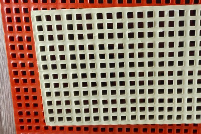
A grating that carries people is not a grating that carries vehicles. The difference is not marketing — it is two orders of magnitude in contact pressure, a different failure mode, and a support frame that most pedestrian installations never need. Yet "heavy duty" is also the most abused word in the FRP grating catalogue: panels sold as vehicle-rated on the strength of a uniformly distributed load number that says nothing about a 95 kN wheel sitting on a 510 mm patch. This guide walks through what actually happens when a wheel rolls onto an FRP panel, how to read and rebuild the load-table arithmetic for yourself, and where the real design work lives — in the frame underneath the grating, not the grating itself.
1. Three Vehicle Regimes, Three Different Problems
Before any numbers, be honest about what will actually drive over the panel. Vehicle duty in industrial sites falls into three regimes, and they fail differently:
- Occasional light vehicles — maintenance pickups crossing a walkway end or parking on a plant access route. Static wheel loads around 3–5 kN, low repetition. This is the easiest regime and the one most often specified correctly.
- Forklift and plant vehicle aisles — the classic FRP case. A 5-tonne forklift with 70% of its weight on the drive axle puts roughly 17 kN per wheel into the floor, thousands of times per year. Fatigue at the cross-rod connections, not ultimate collapse, becomes the issue.
- Highway-class traffic and heavy haul — truck ramps, loading docks taking articulated vehicles, airport-adjacent service roads. Here the design wheel load is set by bridge-code vehicles, and an unsupervised FRP panel is almost never adequate without a purpose-built sub-frame.
European practice gives these regimes a vocabulary. EN 1433 classifies drainage channel assemblies by maximum test load, and the classes have become shorthand for surface traffic duty even outside drainage:
| EN 1433 class | Test load | Typical duty |
|---|---|---|
| A15 | 15 kN | Pedestrian and cycle areas only |
| B125 | 125 kN | Car parks, private driveways, footways with light vehicles |
| C250 | 250 kN | Kerbside channels, slow-moving light traffic |
| D400 | 400 kN | Public carriageways, loading bays, heavy vehicle routes |
| E600 | 600 kN | Docks, freight terminals, heavy forklift zones |
| F900 | 900 kN | Airport aprons, haul roads, extreme industrial loading |
Two cautions before borrowing that table. First, EN 1433 rates the assembly — channel body, frame, locking and surround together — not a bare panel dropped between walls. Second, the test load is not the wheel load; it is a proof load applied through a defined pad, so a "D400" label does not mean the panel sees 400 kN through one wheel. Composite grating systems genuinely certified to B125 or C250 exist, but they are engineered systems, not stock mesh panels.
2. Quantifying the Wheel: HL-93 and the Tire Patch
When the traffic regime is truck-class, the load model to start from is AASHTO LRFD's HL-93 design truck, because it is the most widely referenced definition of a "design wheel" and because manufacturers publish span tables against its older H-20 predecessor. The relevant numbers:
| Parameter | Value | Note |
|---|---|---|
| Rear axle load (HL-93 design truck) | 142 kN (32 kip) | Front axle 35 kN; tandem alternative 110 kN/axle |
| Design wheel load (static) | 71.2 kN | Axle ÷ 2 wheels |
| Dynamic load allowance IM | +33% | All limit states; 75% at deck joints |
| Design wheel with IM | 94.7 kN | The number that actually hits the panel |
| Tire contact patch | 510 × 250 mm | AASHTO LRFD rectangle for design truck/tandem |
| Resulting contact pressure | ≈ 0.74 MPa | Consistent with truck tire inflation pressures |
Notice what the patch does to the arithmetic. The same 94.7 kN spread over a forklift tire footprint would be gentle; squeezed onto 0.128 m² of grating surface it produces a contact pressure comparable to the tire pressure itself. Every structural consequence that follows — bar bending, cross-rod shear, clip loads — flows from that concentration.
3. How a Wheel Load Travels Through a Grating Panel
A grating is not a plate. The wheel load enters through a handful of load bars directly under the patch and spreads to neighbouring bars through the cross rods and the resin body — which is why manufacturer tables for vehicular loading state a distribution assumption explicitly. A typical high-load table (Fibergrate's is the classic example) assumes the load is carried by the bearing bars immediately under the wheel plus four additional adjacent bars, applies the dynamic allowance, then checks bending and deflection with a factor of safety of 2.5 and an absolute deflection cap of 6.4 mm.
Three consequences follow from this load path:
- Deflection governs, not strength. Bearing-bar flexural stress at workable spans stays well below the laminate's 200–300 MPa strength, but the 6.4 mm vehicular deflection cap is eaten up quickly because grating section depth is small.
- Bar pitch sets how widely the load spreads. A 38 mm molded mesh engages more bars under a given patch than a 100 mm pultruded I-bar pattern, which is why mesh size matters as much as depth for wheel duty.
- The patch position matters. A wheel at midspan between supports is the benign case; a wheel directly over a clip line, panel edge or cutout changes the load path entirely and is where field failures concentrate.
A published "high load" table is a contract about assumptions: which bars share the wheel, what deflection limit was used, what safety factor was applied. If your installer drops the panel on a different support arrangement than the table assumed, the table is void.
4. Worked Example: Sizing a 50 mm Panel for a 95 kN Wheel
To show the arithmetic, take the HL-93 dynamic wheel — 94.7 kN on the 510 × 250 mm patch — and check two generic 50 mm panels as simply supported strips between frame beams. The strip method spreads the wheel over the patch width and uses per-metre panel properties (typical published values): pultruded I-bar panel with flexural modulus 13.5 GPa, I = 60 cm⁴/m, S = 24 cm³/m, flexural strength 300 MPa; molded panel with 6 GPa, I = 20 cm⁴/m, S = 10 cm³/m, flexural strength 200 MPa. Allowable stress uses the manufacturer practice of a 2.5 safety factor; deflection is checked against both the 6.4 mm absolute vehicular cap and an L/150 heavy-duty ratio.
| Span L | Pultruded I-bar 50 mm | Molded 50 mm | Verdict (pultruded) | ||
|---|---|---|---|---|---|
| σ (MPa) | δ (mm) | σ (MPa) | δ (mm) | ||
| 250 mm | 60 | 1.2 | 145 | 7.9 | Pass — deflection 1.2 mm |
| 300 mm | 87 | 2.4 | 209 | 16.3 | Pass on 6.4 mm cap; fails L/150 |
| 400 mm | 155 | 7.6 | 371 | 51.6 | Fail — deflection over cap |
| 500 mm | 242 | 18.7 | 580 | 125.9 | Fail — stress and deflection |
| 600 mm | 348 | 38.7 | 835 | 261.0 | Fail — severe |
Read the table the way a reviewer would. For the pultruded I-bar panel, stress never governs at serviceable spans — 87 MPa at 300 mm against a 120 MPa allowable — but deflection climbs with the fourth power of span, so the usable span for a highway wheel is roughly 250–300 mm. The molded panel, despite being the same nominal depth, cannot pass at any span shown: its modulus and section modulus are both roughly a third of the pultruded I-bar's, and the deflection column runs off the page. The strip method assumes ideal load sharing across the patch width, which is more optimistic than the "bars under wheel plus four" distribution rule; treat these numbers as a sizing screen, and confirm final selection against the manufacturer's own vehicular table for the exact panel, mesh and resin.
For perspective, a 5-tonne forklift with 70% of its weight on the drive axle delivers about 17 kN per wheel — a factor of 5.5 below the HL-93 dynamic wheel. This is why forklift aisles are routine FRP grating territory and truck ramps are frame-design territory.
5. Molded, Pultruded I-Bar or Solid Top: Picking the Construction
Wheel duty changes the ranking that pedestrian selection guides give. The comparison that matters for vehicles:
| Property (typical) | Molded 38–50 mm | Pultruded I-bar 50 mm | Relevance to wheels |
|---|---|---|---|
| Flexural modulus | 5–7 GPa | 18–24 GPa (laminate) | Stiffness drives the deflection cap |
| Flexural strength | 150–300 MPa | 500–700 MPa | Rarely governs, but sets the FS floor |
| Load spread | Bi-directional, dense mesh engages many bars | Uni-directional bars; spread depends on cross-rod pitch | Molded spreads a patch better; pultruded resists it better |
| Impact behaviour | Accepts impact without cracking | Stiffer, slightly less impact-tolerant | Forklift flat-tire and dropped-load duty favors molded |
| Long-span capability | Poor above ~1 m under wheel loads | Good with sub-frames at 300–400 mm | Defines the frame spacing budget |
The practical selection logic: dense-mesh molded panels (38 mm mesh or mini-mesh) for forklift aisles and frequent turning zones, where bi-directional spread and impact tolerance win; pultruded I-bar panels for dedicated vehicle lanes where the support frame can be placed at wheel-path spacing and maximum stiffness is wanted. Solid-top or covered panels appear where small wheels — pallet trucks, trolleys with hard castors — would otherwise drop between bars; a hard 100 mm castor on bar centers behaves like a point load on one bar, which is a different (and harsher) problem than the AASHTO patch. Our molded FRP grating and stair tread range, pultruded hollow walkway grating panels and high-density molded grating for chemical plants cover both constructions.
6. Frame Design: The Grating Is Only Half the System
The worked example delivered the punchline already: highway-class wheels demand support spacing in the 250–400 mm range, which no stock panel achieves between bare walls. The vehicle-rated installation is therefore a system — grating plus sub-frame plus surround — and the frame is where the engineering lives:
- Sub-frame beams in the wheel paths. Channels or profiles at 250–400 mm centres, aligned perpendicular to the traffic direction so every bar span stays inside the passing zone. FRP structural sections are a natural fit here; see our guide to web crippling and bearing checks for pultruded beams, because a wheel-path beam sees exactly the local load introductions that article describes.
- Bearing width. Give each panel edge at least 25–40 mm of seat. A 95 kN wheel landing on a panel edge bearing on 15 mm of support crushes resin and kicks the panel.
- Continuity. Two-span continuous panels cut deflection roughly 40% versus simple spans for the same load — worth a bay-length planning pass before adding depth.
- Frame deflection counts too. The total surface movement is grating deflection plus sub-frame deflection. If the frame bends L/250 under the same wheel, your 6.4 mm budget is already half spent before the panel contributes a micrometre.
- Panel orientation. Load bars must span the traffic direction, always. Rotating a panel 90° turns an I-bar panel from a stiff deck into a ladder.
Do not forget the substrate under the frame: a truck wheel also drives vertical load into whatever the frame stands on, and settlement under one beam leg while its neighbours hold creates the rocking that fatigues clips and cracks resin at bearing points. Heavy-duty zones deserve the same foundation attention as any machine base.
7. Drainage, Trench Covers and the EN 1433 Route
Many vehicle-area grating installations are, at heart, drainage problems — trench covers across a wash bay, channel grates in a truck yard, interceptors at a loading dock. This is where EN 1433 earns its keep, because it certifies the assembly: channel body, frame, grate, locking and concrete surround tested together. For an FRP or composite grate to honestly claim B125 or C250 duty, it should come with test evidence for that assembled system, not just a material datasheet.
When a client asks for "a D400 fiberglass grating", the honest answer has three parts. First, the load class applies to the system including its concrete surround and frame — the drainage channel and grate selection guide covers how channel, edge rail and surround contribute. Second, for open-traffic carriageways, ductile-iron remains the default and composites are the corrosion-motivated exception, usually in B125–C250 territory. Third, in chemically aggressive yards — galvanising plants, plating shops, chemical loading aprons — the composite argument gets much stronger, because the alternative is maintaining ductile iron in an environment designed to dissolve zinc and attack cast iron. Our molded fiberglass walkway grating is frequently specified exactly in those hybrid zones: full truck traffic outside the process area, forklift and chemical exposure inside it.
8. Surfaces, Fixing and Field Details That Vehicle Duty Amplifies
Details that are cosmetic on a walkway become structural on a vehicle deck:
- Anti-slip surface. Vehicle areas are usually also braking and turning areas. Grit-topped surfaces with a specified slip rating belong on every ramp and turning zone; the slip standards and grit application practice in our stair tread slip resistance guide apply to vehicle ramps unchanged.
- Clip fixing density. A clip at every second bar pitch minimum in wheel paths, four corners minimum elsewhere, stainless or FRP clips on all four panel edges. Vehicle duty multiplies the uplift and racking forces that clips see; pedestrian clip spacing is not enough.
- Cutouts and sealed edges. Every pipe penetration, drain outlet and sawn edge exposes raw glass and a weakened bar end. Seal cut edges with the panel's own resin and follow the edge-sealing practice in the field cutting and edge sealing guide; a wheel parked on an unsealed cutout finds the delamination path in months.
- Thermal movement. FRP expands at roughly twice steel's rate. Leave the recommended 6–10 mm perimeter gap on long runs; panels butted hard against steel frames will buckle their own edges on a hot afternoon under load.
- De-icing chemicals. Outdoor vehicle decks in cold climates get salt whether you specify it or not — one of FRP's genuine advantages, but the grit surface and resin choice should still be checked against our cold climate design guide.
9. Failure Modes and What Inspection Should Look For
Vehicle-loaded FRP grating almost never fails the way pedestrian grating fails. The recurring field modes, in order of frequency:
- Cross-rod connection fatigue. Repeated wheel passages work the bar-to-cross-rod junction until individual bars lose composite action — visible first as local bar rocking under foot, then as cracking at the junction. A wheel path can be mapped from exactly this symptom.
- Clip pull-through and edge wear. Undersized clip washers pull through the panel under braking loads; edges bear on worn seats and start to fret.
- Local crushing at bearing points. Insufficient seat width plus edge loading indents the panel bottom face — a slow symptom that eventually permits rocking.
- UV chalking of unpigmented tops. Cosmetic at first, but surface micro-cracking on a grit-worn top under a wheel path accelerates fibre exposure.
Inspection intervals should scale with passage counts, not calendar optimism: forklift aisles quarterly, mixed vehicle yards monthly in the first year after installation. The defect grading and repair-trigger framework in our grating condition assessment guide transfers directly to vehicle areas, with one addition — always walk the wheel paths specifically, because the traffic lane concentrates a decade of fatigue into a 500 mm band.
10. A Specification Checklist for Vehicle Areas
When the enquiry goes out, make the supplier quote against numbers, not adjectives:
- Design vehicle and wheel load — state the vehicle, the axle load, and the dynamic allowance you want applied (HL-93 wheel with IM 33% is a defensible heavy-duty basis; a named forklift model is a defensible aisle basis)
- Tire or wheel footprint — dual tires, solid forklift tires, or hard castors change the patch entirely
- Deflection criteria — absolute cap (6.4 mm vehicular practice) and ratio (L/150–L/200), stated separately
- Load distribution assumption — which bars the manufacturer counts as carrying the wheel
- Panel construction, mesh and resin — depth, bar pitch, vinyl ester or isophthalic, grit type
- Sub-frame proposal — spacing, sections, material, and the combined deflection budget
- Fixing schedule — clip type, spacing, torque, material
- Evidence — load tables for the exact panel, and EN 1433/EN 124 test reports where a class is claimed
The pattern across every competent vehicle-area grating specification is the same: someone decided the wheel load first and the panel second. The catalogue-first approach — pick a pretty mesh, then hunt for a table cell that seems to agree — is how "heavy duty" panels end up in wheel paths they were never sized for.
Specifying FRP Grating for a Vehicle Area?
HuanGang supplies molded and pultruded FRP grating for forklift aisles, truck-access areas and chemically aggressive traffic zones, with load tables, grit surfaces, custom cutting and the supporting structural profiles for sub-frame design. Send us the vehicle data and the layout, and our engineering team will return a panel-and-frame proposal with the load arithmetic shown.
Related reading: FRP Grating Load Tables: Reading Uniform and Concentrated Loads · FRP Grating Fabrication and Installation: Field Cutting and Clip Fixing · FRP Drainage Channels and Grates for Industrial Flooring · FRP Pedestrian Bridges and Boardwalk Decking: Live Loads and Deflection Limits · FRP Grating Walkways and Stair Treads · Pultruded Hollow FRP Walkway Grating Panels
Need help selecting FRP products?
Our engineers answer technical questions free of charge.
Ask an Engineer on WhatsApp