
When a beam, column or steel member needs more capacity, the options are usually: replace it, jacket it, or glue something strong onto it. Externally bonded FRP wrapping is the third option — fibre sheets or pultruded laminates bonded to the structure's surface with structural epoxy, adding tensile or confining capacity in millimetres of thickness. It is fast, needs no hot work, and leaves clear heights untouched. It is also the technique with the highest ratio of field failures to design failures in the strengthening world, and nearly all of those failures trace back to one place: the substrate, and how it was prepared. This guide covers the design framework (ACI 440.2R for concrete), the steel-side differences, the surface preparation that decides the outcome, and the acceptance tests that separate a bonded strengthening system from a well-glued decoration.
1. When Wrapping Beats Replacing — and What Both Substrates Share
FRP strengthening earns its keep in four situations: loads increase (new equipment, changed storage, added floors), code demands rise, original construction fell short, or deterioration removed capacity that must be restored. The alternatives — section enlargement, welded steel plates, external post-tensioning — each demand space, weight or hot work that operating plants often cannot afford. On steel structures in particular, bonded CFRP avoids welded plates' heat-affected zones entirely, which matters in confined spaces, near coated surfaces or in facilities where hot-work permits are a battle.
Whatever the substrate, the physics is identical: the system works only through interfacial shear transfer. The adhesive layer moves force between the structure's surface and fibres that are two to ten times stronger than steel but only millimetres thick. Every design limit in every code — debonding strain caps, development lengths, overlap rules — exists because that interface, not the fibre, is the weak link. And every field requirement, from dust removal to dew-point margins, exists because the interface cannot transfer shear across contamination, moisture or laitance.
2. Wet Lay-Up Fabric or Pre-Cured Laminate?
The two delivery forms solve different problems, and most projects use both somewhere:
| Parameter | Wet lay-up fabric | Pre-cured pultruded laminate |
|---|---|---|
| Form | Dry uni/multi-directional fabric rolls, saturated on site with liquid epoxy | Rigid factory-pultruded plates, 1.2–2.0 mm typical, bonded with adhesive paste |
| Ultimate tensile strength (typical CFRP) | 965–1,380 MPa (140–200 ksi) | 2,400–2,900 MPa (350–420 ksi) |
| Geometric adaptability | Wraps columns, curved corners, complex haunches; conforms to any shape | Straight lines only — flat beam soffits, slab undersides |
| Fibre volume fraction | Lower and operator-dependent | Higher and factory-controlled (>60%) |
| Best for | Confinement jackets, shear U-wraps, irregular geometry | Flexural strengthening where full laminate properties matter |
A useful rule of thumb from practice: fabrics for wrapping, laminates for stripping. Anywhere the fibre must bend around a section — column confinement, beam U-wraps, tank shells — wet lay-up wins. Anywhere the strengthening is a straight tension element on a flat surface, a pre-cured laminate delivers more capacity per millimetre with far less dependence on the installer's saturation technique.
3. The ACI 440.2R Design Frame for Concrete
For externally bonded FRP on concrete, ACI 440.2R (Guide for the Design and Construction of Externally Bonded FRP Systems for Strengthening Concrete Structures) is the reference framework most specifications borrow from, even outside the US. Its logic has four layers:
Characteristic material values. Design properties are not catalogue means. The guaranteed tensile strength and rupture strain are defined as the mean minus three standard deviations — a 99.87% exceedance probability — determined per ASTM D3039 with at least 20 replicate specimens. If your supplier cannot produce the statistical basis, the "3,700 MPa" on the datasheet is a marketing number, not a design value.
Environmental reduction factors. The design strength and strain are further reduced by CE for the exposure environment — the mechanism being long-term degradation of the resin and fibre-matrix interface, and, for glass fibre, alkali attack from concrete pore water:
| Exposure condition | Carbon/epoxy | Glass/epoxy | Aramid/epoxy |
|---|---|---|---|
| Interior exposure | 0.95 | 0.75 | 0.85 |
| Exterior exposure (bridges, piers, unenclosed parking) | 0.85 | 0.65 | 0.75 |
| Aggressive environments (chemical plants, wastewater treatment) | 0.85 | 0.50 | 0.70 |
The table explains a specification habit worth copying: carbon fibre is the default in aggressive and exterior service, because its reduction factor barely moves from interior to chemical exposure while glass drops from 0.75 to 0.50. On concrete substrates, bare glass fibre sitting in alkaline pore water is a durability problem before it is a strength problem.
Debonding governs the strain. The failure that actually happens is not fibre rupture — it is intermediate-crack (IC) debonding, where the concrete cover shears away at a flexural crack and the laminate peels off with it. ACI 440.2R therefore caps the usable FRP strain at the smaller of the debonding strain and 90% of the environmental-adjusted rupture strain:
εfd = 0.41 √( f′c / (n·Ef·tf) ) ≤ 0.90·CE·εfu (US customary: f′c in psi, Ef in psi, tf in inches)
Two consequences deserve emphasis. First, the debonding strain falls as plies and thickness increase — doubling the laminate thickness cuts εfd by a factor of 1.41 — which is why stacking plies has sharply diminishing returns and why the equation is sometimes described as producing a "negative strengthening effect" when overdone. Second, the cap is strain, not force: a stiffer, thicker system is allowed less strain, so more material buys less capacity than newcomers expect.
Redundancy and fire. ACI 440.2R's Eq. (9-1) requires the existing structure without FRP to resist 1.1 × dead load + 0.75 × live load of the new design loads (1.0 × live where sustained storage loads exceed about 7.2 kPa). If the FRP is damaged, burned or degraded, the building must not collapse. For fire rating, the code assumes the FRP contribution is lost entirely — ambient-cure epoxies have glass-transition temperatures of 60–82 °C, service temperature is limited to Tg − 15 °C, and fire design proceeds with FRP strength taken as zero, with insulation designed to protect the concrete and steel themselves.
Strength reduction for the FRP contribution. Flexural designs apply ψf = 0.85 to the FRP's contribution; shear designs use 0.95 for fully wrapped sections, 0.85 for U-wraps and 0.70 for two-sided bonding — the factor dropping as the anchorage becomes less reliable.
4. A Worked Example: How Much Strain Is the Wrap Allowed?
Take a realistic strengthening case: one bonded CFRP fabric ply (tf = 1.0 mm, Ef = 230 GPa, guaranteed rupture strain 1.50%) on concrete with f′c = 25 MPa, exterior exposure. Running the debonding equation (f′c = 3,625 psi; Ef = 33.4 × 10⁶ psi; tf = 0.0394 in):
- εfd = 0.41 × √(3,625 / (1 × 33.4×10⁶ × 0.0394)) = 0.0215 (2.15%)
- Rupture cap: 0.90 × 0.85 × 0.0150 = 0.0115 (1.15%)
- Governing usable strain: 1.15% — rupture, not debonding, controls this combination
Switch the same fabric to a weak substrate (f′c = 15 MPa) and the debonding strain drops to about 1.67%, moving the governing limit closer. This is the quantitative meaning of "the substrate matters": every 40% loss of concrete strength strips roughly a fifth of the usable laminate strain.
The second example every steel-side specifier should run once is the stiffness illusion. Compare a 100 × 10 mm steel plate (fy = 250 MPa, E = 200 GPa) against a 100 × 1.4 mm CFRP laminate (E = 165 GPa, ultimate 2,400 MPa):
| Property | Steel plate 100 × 10 | CFRP laminate 100 × 1.4 |
|---|---|---|
| Cross-section | 1,000 mm² | 140 mm² |
| Axial stiffness EA | 200 MN | 23.1 MN (12% of steel) |
| Force at yield / ultimate | 250 kN (yield) | 336 kN (ultimate); ≈243 kN after CE and ψf |
| CFRP thickness needed to match EA | 12.1 mm — 8.7× the 1.4 mm laminate | |
The pattern is the honest summary of FRP strengthening: strength is cheap, stiffness is expensive. A millimetre of CFRP can match a steel plate's force capacity at a fraction of the weight, but if the design objective is deflection control or stiffness redistribution, bonded CFRP is the wrong tool and steel (or deeper sections) remains the answer. Say this to clients before they form a budget from a strength-only comparison.
5. Concrete Surface Preparation: Where Most Failures Are Born
Field studies consistently rank bond-line failure as the dominant failure mode of externally strengthened concrete members, and the bond line is only as good as the concrete underneath it. The preparation sequence is not negotiable:
- Sound the concrete, then remove the unsound. Hammer or chain-drag survey; break out delaminated and carbonated concrete to behind corroded reinforcement; blast exposed rebar clean and treat it (zinc-rich epoxy or equivalent) before rebuilding with structural repair mortar.
- Profile mechanically to CSP 3–4. Grind or abrasive-blast to remove all laitance and expose sound aggregate, per ICRI 310.2R. Acid etching is prohibited — it leaves a weak, calcium-contaminated surface and drives contaminants into pores.
- Level the surface. Fill bug holes and voids with structural epoxy putty; surface deviations beyond roughly 0.8–1.0 mm must be levelled so the fabric beds in full contact. Sharp ridges act as knife edges that cut fibres under tension.
- Treat cracks before wrapping. Cracks wider than about 0.3 mm are pressure-injected with low-viscosity epoxy first — an active crack under a wrap propagates the delamination path for you.
- Round every corner the wrap turns. Re-entrant and outside corners concentrate fibre stress. ACI 440.2R's minimum is 13 mm radius; common practice and the German DAFStb guideline call for 20–25 mm, and sharp corners measurably reduce confinement efficiency on wrapped columns. Build corners up with repair mortar where needed to achieve the radius.
- Dry and warm enough to cure. Substrate moisture below ~4% (a damp-not-wet surface is tolerable for primer only); surface temperature at least 3 °C above dew point; working window typically 10–35 °C. Moisture vapour pushing through uncured resin produces blisters that destroy bond from below.
- Prove the substrate with pull-off. ASTM C1583/C1583M pull-off tests after preparation: ACI 440.2R requires ≥ 1.4 MPa (200 psi) concrete surface tensile strength. At least five tests at representative locations; if the design assumed higher values, test to those.
The pull-off number alone is not the pass. A 2.0 MPa reading that breaks cleanly at the bond line is a fail — it proves the substrate adhesive strength is the weak link. The acceptance rule is both conditions: load above the threshold and failure occurring inside the concrete.
6. Steel Substrates: Cleanliness, Timing and Galvanic Isolation
Preparing steel for bonded FRP is a different craft with a different failure chemistry:
- Blast to Sa 2½. ISO 8501-1 near-white blast cleaning, removing all rust, mill scale and coating from the bond area; the surface should show the metal's uniform grey with only slight tinting. Steel is unforgiving: bond strength follows the cleanliness almost linearly, which is why the ISO 8504 preparation methods and ISO 8503 profile requirements transfer from painting practice with the same rigour.
- Work inside the corrosion window. Blast-cleaned bare steel begins oxidising within minutes in humid air. Degrease, then bond — or primer-coat — as soon as possible after blasting; every hour of delay in a damp environment is bond strength quietly leaking away. Some system guidelines permit up to days between preparation and bonding, but the honest default is same-shift.
- Break the galvanic circuit. Carbon fibre is electrically conductive and strongly cathodic against steel. Where moisture and salts can reach a direct carbon-steel contact, the steel corrodes at the laminate's edges — accelerated exactly where the strengthening matters. Mitigations: a dielectric barrier layer (glass-fibre ply between carbon and steel, insulating primer, or adhesive with dielectric filler), plus perimeter sealing to keep electrolytes out of the interface. Note the mirror-image trap: over-sanding a CFRP plate's bonding face can expose carbon filaments that then contact the steel — handle the laminate surface as deliberately as the steel.
- Edge sealing and coating compatibility. Seal laminate ends to block peel initiation and water ingress; apply UV-protective topcoats compatible with the epoxy (solvent wiping needs system-maker approval — some solvents attack the resin surface they are meant to clean).
On steel, also weigh the failure context. A welded plate has a known, inspectable failure mode; a bonded wrap degrades gracefully but quietly. That argues for conservative design strains on steel members and for inspection access being part of the design, not an afterthought.
7. Installation Sequence and Lamination Quality
A wet lay-up that will survive inspection follows a fixed rhythm, and shortcuts in it show up as delaminations at handover:
- Primer on the prepared substrate — penetrates and seals; a second thin coat on porous or carbonated concrete once tack-free.
- Putty/leveling — bedding layer for the fabric; full cure before priming where a separate pass.
- Saturate the fabric with mixed epoxy at the specified ratio — 3 minutes of mechanical mixing to a uniform colour, no air entrainment; pot life respected.
- Apply and consolidate — fabric into the resin with a ribbed (grooved) roller to force impregnation and push out entrapped air; work air out edge-to-centre, never drag dry.
- Multiple plies wet-on-wet where the design stacks layers, with lap splices staggered and a minimum overlap of 100 mm (150–200 mm is common practice on steel); fibre alignment within about 5° of the design direction — small angle errors cost substantial strengthening.
- Cure — typically 7 days at 20 °C for full ambient cure; protect from rain, dust, UV and temperature swings during cure.
- Topcoat — mandatory outdoors for UV; this is also where colour-coded inspection bands or fire-protection systems are integrated if the design requires them.
Alignment deserves its own sentence in every method statement: fabric kinks, folds or waviness observed during installation are reportable defects, not cosmetic issues, because fibre misalignment redistributes the load you are paying to strengthen.
8. Acceptance Testing and the Records That Matter
The acceptance package for a bonded FRP system should be defined before the crew mobilises, and it is short:
- Substrate pull-off (before work): ASTM C1583, ≥ 1.4 MPa with concrete-mode failure.
- In-process checks: fibre orientation, ply counts, overlaps, resin mixing records, ambient temperature and dew-point logs at each shift.
- Cured-laminate verification: acoustic (coin or hammer) tap survey or thermography to find voids and delaminations; any hollow-sounding area larger than the specification's limit gets cut out and re-laminated.
- Completed-system pull-off where specified — industry practice codified in ACI SPEC-440.12-22 requires the pull-off value to exceed 200 psi and the failure to occur in the concrete, tested at a defined frequency per area and per day.
- Records: batch numbers of every fabric and resin lot, mixing ratios, ambient conditions, ply maps and repair locations — because the system's service life will be argued someday, and the argument is won with batch records.
The pull-off rule bears repeating because it is counterintuitive to inspectors raised on steel codes: a high number with a clean bond-line break fails. The test is measuring the substrate's ability to anchor the system, not the glue's stickiness.
9. What FRP Wrapping Cannot Do
Honest specification includes the refusal list, because most strengthening-project disappointments come from asking FRP to solve a problem it was never meant to touch:
- Punching shear. ACI 440.2R offers no two-way shear strengthening method for slabs — flat-plate punching capacity around columns and rack posts cannot be recovered with a wrap.
- Fire-rated load path, unassisted. The code's own position is that FRP contribution is zero in fire; insulation protects the concrete and steel, and the design must stand without FRP under the fire load combination.
- Stiffness problems. As the worked example showed, matching a steel plate's stiffness needs ~9× the laminate thickness. Deflection-governed structures need steel or deeper sections.
- Confinement of extreme sections. For column confinement, efficiency collapses on rectangular sections with aspect ratios beyond about 1.5 (and side dimensions beyond 900 mm); such sections need reshaping toward circular/elliptical or supplemental anchors.
- Weak substrates. No amount of fabric fixes concrete that cannot reach 1.4 MPa pull-off, or steel whose thickness is being lost faster than the bonding area can hold. Substrate rehabilitation comes first — always.
FRP strengthening multiplies what a sound structure can carry. It never creates structure where the substrate has already stopped working — and it cannot carry the load alone if it is lost, which is why every serious code builds the redundancy check (1.1D + 0.75L) into the first chapter of the design, not the last.
10. A Specification Checklist for Wrap Strengthening Projects
Items that separate procurable specifications from wishlist documents:
- Design basis — ACI 440.2R (or national equivalent) named, with the governing strain limits and the Eq. (9-1) redundancy check shown in the calculation package
- Material data with statistics — guaranteed (mean − 3σ) properties per ASTM D3039, CE applied to the actual exposure, batch traceability required
- System, not ingredients — fabric, resin, primer and putty as one qualified system; no mixing brands mid-project
- Surface preparation spec — CSP 3–4 (concrete) or Sa 2½ (steel), corner radii, moisture and dew-point limits, prohibition on acid etching
- Pull-off criteria — threshold and failure mode, test frequency, and the cut-out-and-repair rule for hollow areas
- Installation window — temperature, humidity, and who owns the dew-point decision at 06:00 on site
- Fire and UV protection — topcoat system, and the fire strategy confirming the un-FRP'd structure carries the required combination
- Records deliverable — batch log, ply maps, ambient logs, test results, as-built ply layout
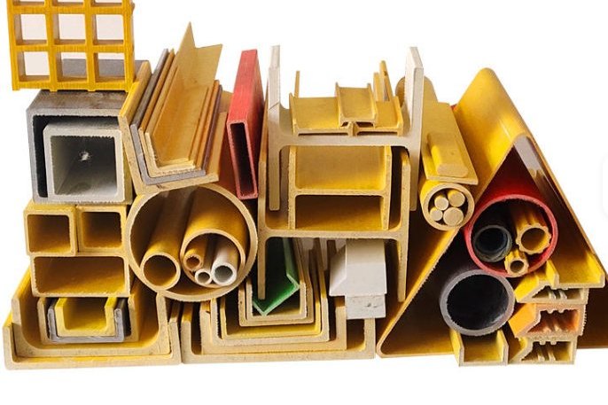
For the structural side of FRP beyond bonded wraps — pultruded sections used as new framing, bracing and support members around strengthened structures — our pultruded FRP angle profiles for structural construction, pultruded FRP I-beam and H-beam structural supports and high-strength FRP I-beam profiles cover the load-bearing complement to bonded strengthening work.
Planning an FRP Strengthening Project?
HuanGang manufactures pultruded FRP structural profiles and complements bonded strengthening systems for concrete and steel retrofit work, with export documentation and engineering support for specification review. Share your member drawings and load targets, and our team will help you match the strengthening method — bonded wrap, laminate or new pultruded framing — to the structure you actually have.
Related reading: FRP Structural Adhesive Bonding: Surface Preparation and Joint Geometry · FRP Rebar for Reinforced Concrete: ACI 440.1R Design Basis · FRP Structural Bolted Connections: Bolt Grades and Bearing Design · FRP Pipe Rehabilitation with Cured-in-Place Liners · Pultruded FRP Angle Profiles · Pultruded FRP I-Beam Structural Supports
Need help selecting FRP products?
Our engineers answer technical questions free of charge.
Ask an Engineer on WhatsApp