
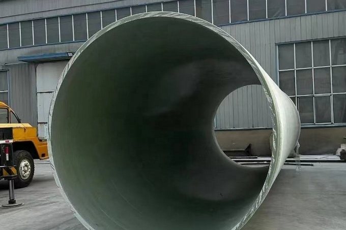
Wet flue gas desulfurization (FGD) is one of the few services in which a pipe must resist chemical attack, abrasive wear and permeation-driven blistering at the same time. Absorber recirculation lines carry limestone and gypsum slurry at 45–55 °C and pH 4.5–5.8, with chloride levels that would pit austenitic stainless steel within months. Many 1990s-era plants learned this the hard way: rubber-lined carbon steel recycle lines blistered, the rubber tore away and lodged in spray nozzles, and permeation corroded the steel beneath the lining. Vinyl ester-based FRP pipe has since become the default replacement — a resin supplier survey credits it with more than 150 FGD plant installations since the early 1970s, including 75 limestone slurry piping systems commissioned between 2004 and 2010 alone. This guide explains how to specify FRP pipe for FGD slurry service: the environment you are designing for, the velocity window that balances settling against erosion, the liner architecture that carries the wear, resin selection, qualification standards, and a worked sizing example.
1. What FGD Slurry Actually Is: The Design Environment
Before comparing materials, quantify the service. A typical limestone forced-oxidation absorber loop looks like this:
| Parameter | Typical value | Why it matters |
|---|---|---|
| Medium | Limestone reagent slurry, gypsum recirculation slurry, filtrate | Each line has a different solids content and abrasivity |
| Solids content | 10–20 wt% in absorber recirculation; up to ~30 wt% reagent feed | Sets erosion rate and settling behaviour |
| Slurry density | 1,050–1,250 kg/m³ (absorber recirculation) | Drives pump head and hoop stress |
| pH | 4.5–5.8 (absorber); 5.5–6.2 in reagent feed | Mild acidity attacks steel passivity, not glass |
| Temperature | 45–55 °C continuous; quench zones transient hotter | Sets resin HDT margin |
| Chloride | ~5,000 ppm typical, up to 20,000 ppm reported; designs often basis 20,000 mg/L | The primary driver of stainless steel pitting |
| Fluoride | Dissolved fluorides present from coal | Aggressive to both steel and silica fillers |
The chloride number deserves emphasis. Resin-manufacturer technical literature for FGD linings reports chloride concentrations of about 5,000 ppm in the immersion zone at pH 5 and roughly 52 °C, with values as high as 20,000 ppm depending on the coal source and the degree of chloride purge. A Chinese FGD design practice commonly adopts 20,000 mg/L as the design basis. This is precisely the concentration band where 316L and even duplex 2205 lose their margin in the presence of scale and crevices, and it is why FRP, which has no metallic passive film to break down, competes so well in this service.
2. Three Failure Mechanisms, Not One
FGD slurry piping fails in three distinguishable ways, and a specification that only addresses corrosion will miss the other two:
- Corrosion. Chloride-bearing acidic slurry pits and crevice-corrodes stainless steels; permeation through non-metallic linings corrodes the steel shell beneath. FRP is immune to both because the glass/resin composite does not depend on a passive film and does not support an under-film cell the way a bonded rubber lining on steel does.
- Erosion. Gypsum and limestone particles abrade the wall, concentrating at the outer radius of elbows, at tees and downstream of pump discharges. Published FGD design practice notes that abrasivity scales with particle density, the cube of particle size, solids concentration and roughly the square of velocity — which is why velocity control (Section 3) is the single most effective lever.
- Permeation and blistering. In lined steel pipe, water and chloride diffuse through rubber or thin organic linings, building osmotic blisters that eventually rupture. A well-built FRP pipe has no steel substrate to protect — the corrosion barrier works on a different principle: it must simply remain chemically intact.
A 2,000 MW US utility replaced the original rubber-lined carbon steel recycle piping of its ten FGD absorbers after only a few years of service: blisters formed, the lining peeled and plugged spray nozzles, and fluid permeation corroded the steel and caused through-wall leaks. The replacement — fire-retardant vinyl ester FRP with a reinforced erosion-resistant liner — was stress-analysed with the entire erosion liner treated as corrosion allowance, and remains a reference installation for the material class.
3. Velocity Selection: The 1.5–2.4 m/s Window
Slurry hydraulics punish both extremes. Too slow, and a heterogeneous bed forms that smears wear along the pipe bottom and eventually blocks the line. Too fast, and erosion — which scales with velocity squared to velocity to the 2.5 — eats the liner years early. Wet-FGD design practice has converged on a volumetric velocity window of about 1.5–2.4 m/s for limestone and gypsum slurry in horizontal runs, deliberately maintaining a slightly non-homogeneous flow regime rather than the (energy-expensive) fully homogeneous one.
| Duty | Recommended velocity | Rationale |
|---|---|---|
| Limestone reagent feed (fresh, fine grind <200 µm) | 1.5–2.0 m/s | Fine solids settle slowly; abrasivity moderate |
| Absorber recirculation (gypsum slurry, 10–20 wt%) | 1.8–2.4 m/s | Higher density and solids; keep suspended |
| Gypsum bleed / dewatering feed | 1.5–2.0 m/s | Coarser crystals; avoid over-velocity at elbows |
| Oxidation air lines | Gas duty, 10–20 m/s | Different mechanism; watch condensate washdown |
The erosion arithmetic is unforgiving. Taking a baseline wear rate at 2.0 m/s, raising velocity to 3.0 m/s multiplies metal/composite loss by roughly 2.3–2.8×, and 4.0 m/s by 4–5.7×:
| Velocity | Relative wear (v²) | Relative wear (v^2.5) | Illustrative life of a 2.54 mm liner* |
|---|---|---|---|
| 1.5 m/s | 0.56× | 0.49× | ~25+ years |
| 2.0 m/s | 1.00× | 1.00× | ~25 years |
| 2.4 m/s | 1.44× | 1.58× | ~16 years |
| 3.0 m/s | 2.25× | 2.76× | ~9 years |
| 4.0 m/s | 4.00× | 5.66× | ~5 years |
*Illustrative only: assumes 0.10 mm/year wear at 2.0 m/s. Use it for ranking, not as a guarantee — actual wear depends on crystal size distribution, hardness and duty cycle.
4. Liner Architecture: What the 100-Mil Barrier Really Contains
In slurry-rated FRP pipe, the wear surface is not an afterthought — it is an engineered laminate called the erosion/corrosion barrier. A representative premium construction (as published for a 150 psi / PN10 FGD pipe line) consists of:
- One layer of C-glass or polyester surfacing veil (the chemical barrier — resin-rich, glass-free surface so no fibres are exposed to the slurry);
- Two layers of chopped strand mat in a specially formulated abrasion-resistant resin matrix (the anti-wicking and wear layer);
- A total barrier thickness of about 100 mil (2.5 mm), sometimes quoted by vendors as >2.5 mm for slurry service;
- A structural wall behind it (filament wound hoop/helix layers) sized separately for pressure.
Three specification points follow. First, the barrier and the structure are separate design items: the structural wall is sized from hydrostatic design stress established by regression testing (Section 6), while the barrier is sized for the wear environment and should not be counted as pressure-bearing. Second, abrasion-resistant filler matters: silica or similar hard fillers dispersed in the barrier resin take the particle impact instead of the neat resin. Third, glass type matters: ECR glass offers better acid resistance than standard E-glass, and C-glass veil is preferred at the wear surface; premium FGD lines use ECR throughout the structural wall.
5. Resin Selection: Why Vinyl Ester Is the Default
The standard resin for FGD slurry piping is a bisphenol-A epoxy vinyl ester. It combines acid resistance across the pH 4.5–6 band with the toughness needed to survive thermal shocks when the absorber is washed or the loop is started against a hot-soaked line. Resin suppliers publish HDT values of roughly 104 °C for the standard BPA vinyl ester grade and about 154 °C for the heat-cured/modified grades; commercially, slurry pipe lines rate continuous service at about 80–90 °C with instantaneous tolerance claimed up to 200–220 °C for wet-lay liners — a number you should treat as a short-excursion ceiling, not a design point.
Selection guidance:
- BPA epoxy vinyl ester (e.g. HDT ≈104 °C class) — the default for absorber recirculation and reagent lines at 45–55 °C;
- Fire-retardant vinyl ester (brominated) — specified where the duct or pipe route needs a flame-spread rating (common in stack-adjacent service);
- Higher-HDT vinyl esters (≈154 °C class) — for quench or inlet-corridor sections that see temperature excursions;
- Isophthalic polyester — acceptable for cool, low-solids filtrate lines on budget, but loses margin on both temperature and toughness.
For a deeper comparison of resin families across chemical services, see our resin selection guide for vinyl ester vs isophthalic and orthophthalic polyester systems.
6. Standards and Qualification: Building a Spec Without a Dedicated FGD Code
There is no single international standard titled "FRP pipe for FGD". Specifications are therefore assembled from the pressure-pipe qualification framework plus project-specific wear and chemical requirements:
| Standard | Role in an FGD pipe specification |
|---|---|
| ASTM D2996 | Filament-wound RTRP pipe — classification and manufacturing requirements for the structural wall |
| ASTM D2992 | Hydrostatic design basis by regression (Procedure B static or Procedure A cyclic); the pressure class of a 150 psi FGD line is established by this testing |
| ASTM D6041 | Contact-moulded FRP pipe and fittings — used for the fittings and joint designs in slurry systems |
| ASTM D5421 | Contact-moulded FRP flanges — qualification of the flange hubs used on slurry lines |
| ASTM C581 | Chemical resistance of FRP in liquid service — laminate coupons immersed in representative slurry/filtrate chemistry |
| ASTM D2583 | Barcol hardness — cure verification, typically acceptance at ≥90% of the resin manufacturer's minimum |
| ISO 14692 family | Petroleum-industry GRP piping framework; useful for QA structure and installation tolerances even where the chemical service is FGD |
Two clauses worth writing into any FGD pipe specification: (a) the pressure qualification must be by regression (D2992), not a single short-term burst, because slurry lines see decades of cyclic pump starts; and (b) the corrosion/erosion barrier thickness must be measured and reported (e.g. by sectioning or ultrasonic survey on witness coupons), since it is the item the service will actually consume.
7. Material Options Compared: FRP vs the Alternatives
| Option | Corrosion in FGD chemistry | Erosion resistance | Failure mode to watch | Typical verdict |
|---|---|---|---|---|
| FRP (vinyl ester + erosion barrier) | Immune to chloride pitting; no under-film corrosion | Good with filled barrier; predictable wear | Liner wear-through after years (measure, re-line) | Default for recirculation and reagent lines |
| Rubber-lined carbon steel | Good while intact | Excellent (soft liner takes impact) | Blistering/peeling; permeation rusts shell; rubber in nozzles | Works in coarse duties; the historical FGD failure case |
| 316L stainless | OK only at low chloride; pitting with scale/crevices | Moderate; work-hardens | Pitting and chloride SCC at welds | Limited to low-chloride filtrate/utility duties |
| 2205 / 904L / 6-Mo alloys | Extends chloride range substantially | Moderate | Cost; still erosion-sensitive at elbows | Justified only for hot, high-chloride niches |
| UHMWPE / HDPE | Excellent | Excellent | Temperature limit (~60–70 °C), pressure class | Good for cool, low-pressure reagent feed |
| Ceramic-lined steel | Gaps at joints attack steel | Outstanding | Weight, joint complexity | Niche: highest-wear chutes and pump internals |
8. Wear Points: Elbows, Tees and Supports
Erosion concentrates where flow direction changes. FGD piping practice therefore specifies:
- Long-radius bends — Chinese slurry-piping design rules used on FGD projects require bend centreline radius of at least 4× nominal diameter (R ≥ 4D) wherever a direction change is needed; short-radius 1.5D elbows concentrate the particle impact on a small outer-radius patch. On a DN600 line that is the difference between a 0.90 m and a 2.40 m radius.
- Extra barrier thickness at fittings — elbows and tees are built with a thicker erosion layer than straight pipe, because field surveys show the outer radius wears several times faster than straight-run bottoms.
- Support spacing reduced 20–30% versus clean-water practice, and vibration-resistant supports near pump discharges — slurry lines are heavier (1,050–1,250 kg/m³) and pumps transmit pulsation.
- No throttling on slurry duty — valves are full-bore rubber-lined or ceramic types; partially open trim creates a local high-velocity jet that will excavate any liner.
- Flush and drain provisions on every low point; gypsum sets solid when the loop is idle, and the restart event (breaking a set slurry plug) is a classic liner-damage scenario.
Stress analysis practice for FGD FRP lines mirrors the wear reality: treat the entire erosion liner as corroded-away in the structural model, include torsion in the code stress equations, and verify support locations with finite-element checks at anchors and risers — the 2,000 MW replacement project cited above stiffened a vertical riser shear collar with a pretensioned steel strap after FEA showed high radial stresses.
9. Worked Example: Sizing an Absorber Recirculation Line
Consider a single absorber recirculation header handling 2,000 m³/h of gypsum slurry (15 wt% solids, density 1,200 kg/m³, 50 °C) at pressure class PN10. The table below was generated by a documented calculation script (Colebrook friction, thin-wall hoop stress, wear scaling):
| Quantity | Value | Comment |
|---|---|---|
| Nominal bore | DN600 (ID 600 mm) | Chosen so velocity lands in the design window |
| Flow velocity | 1.96 m/s | Inside the 1.5–2.4 m/s FGD window |
| Reynolds number | 1.07 × 10⁶ | Fully turbulent |
| Darcy friction factor | 0.0131 (ε = 0.05 mm) | Smooth FRP bore; no corrosion roughening over life |
| Pressure drop | 5.1 kPa per 100 m (0.43 m slurry head) | Smooth bore keeps lifetime pumping cost low |
| Hoop stress at PN10 | 31.6 MPa (t = 9.5 mm) | Within vinyl ester laminate capability; class confirmed by D2992 regression |
| Hoop stress at PN6 | 18.9 MPa (t = 9.5 mm) | Equivalent line rated PN6 keeps a wider margin |
| Solids mass flow | 360 t/h | Why velocity discipline matters at this scale |
| 90° bend radius (R = 4D) | 2.40 m | vs 0.90 m at 1.5D |
| Liner life at 2.0 m/s | ~25 years (illustrative) | Drops to ~16 y at 2.4 m/s, ~9 y at 3.0 m/s |
Every derived number in the table comes from the scripted calculation; the velocity assertion and the pressure-drop sanity band were checked automatically, which is the same discipline we recommend in your own project reviews — ask the vendor for the calculation, not just the conclusion.
10. Buyer's Checklist for FGD Slurry Pipe
Before awarding a slurry-pipe package, require the following in the technical bid:
- Resin identity and HDT, stated by grade, with the fire-retardant variant flagged if the route needs it;
- Barrier build-up (veil type, chopped-strand layers, filler system) and measured total barrier thickness, with witness coupons;
- Structural wall qualification: D2992 regression basis, test pressure class, and stiffness class if buried sections exist;
- Flange qualification (D5421 or equivalent) and drilling pattern (ASME B16.5 Class 150 or EN 1092-1) to match the pumps and valves;
- Fitting erosion allowances: thicker barrier at elbows/tees, R ≥ 4D bend availability;
- Jointing plan: adhesive or butt-and-wrap field joints with qualified laminators, plus hydrotest acceptance criteria;
- Chemical resistance evidence (C581 coupons in the actual slurry chemistry, not distilled water);
- Barcol cure acceptance at ≥90% of the resin manufacturer's minimum, measured on delivered pipe.
For field jointing and pressure-test practice once the pipe arrives, continue with our FRP pipe installation and pressure testing guide, and for buried sections of filtrate or gypsum slurry, the thrust and anchor block design guide covers restraint of the dead legs and bends. Our filament-wound FRP pressure pipe is manufactured to the D2996/D2992 qualification path described above, and our custom GRP process pipes can be built with the filled erosion barrier in any of the classes discussed here — send us your slurry analysis and flow schedule for a lined configuration matched to your duty.
Need help selecting FRP products?
Our engineers answer technical questions free of charge.
Ask an Engineer on WhatsApp