
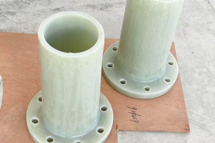
Most FRP flange failures are not material defects — they are installation events. A GRP flange tightened like a steel flange cracks at the hub; a joint pulled together by the bolts carries a permanent bending moment in the neck; a ring gasket on a flat-faced flange leaves the exposed face to chemical attack. The physics is different from steel: glass-reinforced plastic has roughly one-tenth the stiffness, creeps under sustained bolt load, and does not yield locally to forgive misalignment. This guide walks through the four things that actually determine whether an FRP flanged joint survives its first decade: choosing the right gasket, meeting the alignment tolerances of ISO 14692-4, using the torque values and sequence that FRP flanges can tolerate, and re-tightening for the creep relaxation that is inherent to the material.
1. Why an FRP Flange Is Not a Small Steel Flange
Three material properties drive every rule in this article:
- Low stiffness (E ≈ 8–20 GPa, vs 200 GPa for steel). Flange rotation and hub bending appear at bolt loads that a steel flange would shrug off. Over-torque does not stretch the flange ring — it cracks it.
- Creep under sustained load. Bolt clamping force decays as the laminate compresses the gasket and relaxes itself. Manufacturers report 15–25% loss of initial clamping within the first day, which is why every major installation guide mandates a re-torque after 24 hours (and a check one hour after initial tightening).
- No local yielding. A steel flange denting at a bolt hole absorbs an overload; an FRP flange responds with a resin crack that grows. Alignment must be corrected by the piping, never by the bolts.
Rule of thumb used across GRP manufacturers: FRP flanges take roughly 30–45% of the torque of an equivalent steel flange. On an M16 bolt that is about 30–55 N·m instead of 80–120 N·m. Exceeding the maximum "without consulting the manufacturer may cause permanent damage to GRP flanges."
2. Know Your Flange Type Before You Bolt It
GRP pressure systems use three flange styles, each with its own gasket geometry, and they must not be mixed up on site:
| Flange type | How it is made | Sealing arrangement | Notes for the installer |
|---|---|---|---|
| Full-face contact-moulded flange | Hand lay-up on the pipe end or moulded; ASTM D5421 covers contact-moulded flanges | Full-face gasket spanning the entire flange face; bolts pass through the gasket | Never substitute a ring gasket — the exposed face between gasket and bore would be attacked by the medium |
| Stub-end (lap-joint / Van Stone) | Moulded FRP stub flange rotating under a separate backing ring (FRP, ductile iron or steel) | Seal at the stub face; O-ring or profile gasket with steel ring on flat faces | The rotating ring solves bolt-hole alignment; check the backing ring is flat — a warped ring cracks the stub during bolt-up |
| Grooved O-ring face | Machine-made flanges per ASTM D4024, or contact-moulded with machined groove | Elastomeric O-ring seated in a face groove; only one mating flange is grooved | Inspect the O-ring by stretching ~30% around its length; discard any with cracks; secure in groove with tape strips, never tape across the sealing face |
Drilling follows ASME B16.5 Class 150 or EN 1092-1 patterns so the flanges match pumps, valves and steel spools. A detail that matters later in the alignment section: bolt holes are commonly punched or drilled 3 mm larger than the bolt — this allowance is intended to absorb small bolt-circle misalignment, and the standard alignment tolerances already account for it.
3. Gasket Selection: Full Face, and Thickness by Temperature
For FRP flanges the gasket does two jobs: it seals, and it spreads bolt load over the largest possible area to protect the laminate. Selection by service temperature:
| Service temperature | Gasket type | Thickness | Why |
|---|---|---|---|
| Up to ~80 °C | Full-face EPDM | 3 mm | Soft, wide, low seating stress — ideal partner for GRP faces; standard for water/wastewater duties |
| 80–150 °C | PTFE envelope over compressed-fibre core | 1.5–3.0 mm | Chemical resistance across acids and solvents; the envelope protects the fibre core |
| Above 150 °C | Expanded PTFE (ePTFE) | Per manufacturer | Conforms at low bolt load; only practical choice at the top of the FRP temperature range |
| Acidic chemical duty (ambient–60 °C) | Full-face PTFE or envelope | 1.5–3 mm | EPDM swells in some oxidising acids — check compatibility list, not just temperature |
Three gasket rules that prevent the classic field defects: the gasket inside diameter must exceed the bore by at least ~3 mm per side, so no gasket lip protrudes into the flow to catch debris and seed turbulence; the gasket outside diameter must stay inside the bolt circle on non-full-face arrangements so the bolt load acts on the gasket and not on air; and gaskets must be stored flat, replaced if creased, and never fixed with tape or adhesive across a sealing face.
4. Alignment Tolerances: What ISO 14692-4 Actually Requires
Piping spools must align by their supports, not by their bolts. The GRP piping standard for fabrication, installation and operation (ISO 14692-4:2017) gives explicit numeric tolerances, reproduced below:
| Diameter range | Flange misalignment | Separation between spools |
|---|---|---|
| 50–300 mm | ±1.6 mm | ±2 mm |
| 300–1,200 mm | ±3.2 mm | ±5 mm |
| 1,200–4,000 mm | ±5 mm | ±10 mm |
The same standard limits the maximum gap at the joint to 6 mm and sets a global tolerance of ±6 mm in all directions for finished pipework. Manufacturer installation guides land on compatible numbers: mating flanges should touch at their inside edges or stand no more than a 2–3 mm gap apart, and any larger gap or offset must be corrected by re-supporting the pipe — "any misalignment would require high bolt torque and could lead to high stress at the flange."
Why the tolerance band is so much tighter than steel practice? Because pulling a flange face square with bolts imposes a bending moment the hub cannot redistribute. The arithmetic is stark: the gap difference across a flange face scales with the face diameter times the sine of the angular error.
| Flange face | 0.5° angular error | 1.0° angular error |
|---|---|---|
| DN200 (349 mm face) | 3.0 mm gap difference | 6.1 mm — already past the 6 mm joint-gap limit |
| DN500 (575 mm face) | 5.0 mm | 10.0 mm |
| DN600 (711 mm face) | 6.2 mm | 12.4 mm |
A single degree of slope on a DN600 flange creates more gap variation than the entire permissible joint gap — the numbers explain, better than any warning label, why "never use the bolts as an alignment tool" is written into every GRP installation guide.
5. Torque Values: The Numbers to Put on the Work Order
FRP flange torques cluster in a narrow band regardless of manufacturer. Published installation guides for large GRP systems specify 35 N·m as the working torque with 70–110 N·m as the ceiling depending on diameter and gasket type, and general FRP practice tables place each bolt size at 35–45% of the steel value:
| Bolt size | FRP torque (N·m) | Steel torque for comparison (N·m) | FRP/steel |
|---|---|---|---|
| M12 | 15–25 | 40–60 | ~38–42% |
| M16 | 30–55 | 80–120 | ~38–46% |
| M20 | 40–70 | 140–180 | ~29–39% |
| M24 | 50–80 | 200–250 | ~25–32% |
Manufacturer-specific ceilings for large-diameter O-ring-faced GRP flanges (DN350 and up) are consistent: tighten to 35 N·m, then in sequence raise to 65–100 N·m until the faces touch with a 2–3 mm inside gap, never beyond ~110 N·m without manufacturer approval. Two hardware rules are universal: use washers under every nut on GRP flanges to spread the load, and lubricate the threads so the torque actually reaches the joint instead of being consumed by friction. Use 316L bolts in corrosive service — corroding carbon-steel bolts expand and crack the laminate around the bolt hole within a couple of seasons.
6. The Tightening Sequence: Passes, Cross-Pattern and Re-Torque
The sequence exists to load the gasket uniformly so the flange faces stay parallel. The canonical procedure, straight from GRP installation guides:
- Clean both flange faces and the gasket; inspect the gasket and discard damaged ones.
- Align the flanges (Section 4 tolerances) and bring them together by hand without springing the pipe.
- Insert bolts, washers and nuts; lubricate; snug all nuts finger-tight.
- Pass 1: 30% of final torque (e.g. 15 N·m for a 50 N·m target) in the star/cross pattern.
- Pass 2: 60% of final torque (30 N·m), same pattern.
- Pass 3: 100% of final torque (50 N·m), same pattern — never one continuous pull per bolt.
- Re-check the full pattern after one hour and top up to final torque if any bolt has relaxed.
- Re-torque all bolts after 24 hours of service — laminate creep costs 15–25% of clamping force in the first day.
Impact wrenches are inappropriate: the whole point of a calibrated torque wrench at 30–55 N·m is that FRP fails quietly but permanently. For flanges with more than 20 bolts, extend the same incremental pattern across the bolt circle rather than inventing a local sequence.
7. Worked Example: What the Torque Actually Does to the Gasket
The reason an M16 bolt at 50 N·m is enough — and at 110 N·m is destructive — is visible in the gasket stress arithmetic. Take a DN200 ASME B16.5 Class 150 joint with 8 bolts. Bolt load follows F = T/(K·d) with a lubricated nut factor K ≈ 0.15; seating stress equals total bolt load divided by gasket area. The numbers below come from a scripted calculation with automatic sanity checks:
| Quantity | FRP practice | Steel practice |
|---|---|---|
| Torque per M16 bolt | 50 N·m | 110 N·m |
| Bolt load (K = 0.15) | 20.8 kN | 45.8 kN |
| Gasket style and area | Full-face, 580 cm² | Raised-face, 223 cm² |
| Gasket seating stress | 2.88 MPa | 16.4 MPa |
| After 15–25% creep relaxation | 2.44–2.16 MPa | — |
Read the two right-hand columns together: steel practice uses 2.2× the torque, yet lands 5.7× the seating stress, because the raised-face gasket area is less than half and the torque is more than double. The FRP joint works because the full-face gasket's huge area converts a modest bolt load into an adequate, laminate-safe seal pressure — and it still retains more than 2 MPa after a day of creep. That is the entire design logic of the low torque values, in one table. (A 25% relaxation case still holds 2.16 MPa, comfortably above what a soft 3 mm EPDM full-face gasket needs at typical PN10 water duties.)
8. What Over-Torque and Misalignment Do to the Flange
When an FRP flange fails in the field, the fracture pattern tells you which rule was broken:
- Cracks radiating from bolt holes — torque far beyond the table, or missing washers concentrating load on the hole edge.
- Hub/neck cracking on one side — the flange was pulled square by its bolts over a misaligned spool; the bending moment that the bolts introduced has fatigued the neck.
- Face delamination around the bore — a ring gasket used on a full-face flange, so the unsupported annulus worked under pressure cycles.
- Leak that reappears after re-tightening — gasket destroyed by the first over-torque, or creased during assembly; replace the gasket, do not keep adding torque.
None of these are repairable by more torque. Damaged flange faces are rebuilt by cutting the flange off and butt-and-wrapping a new one, connected to the mating equipment first so that no torsion is trapped in the new joint — as the maintenance manuals for large GRP systems explicitly instruct.
9. Support the Joint: Loads Flanges Must Not Carry
A flanged joint is a sealing interface, not a structural node. Keep the following out of the bolt group:
- Valve weight — heavy valves and actuators get independent supports on both sides; an unsupported valve hangs its mass off the GRP flange face.
- Pipe thermal movement — expansion forces must be absorbed by the piping's guides and expansion arrangements, not by prying a flange face sideways. Where equipment must be periodically dismantled, install a dismantling joint or mechanical flange adaptor so spools can move apart without loading the equipment nozzle.
- Pump vibration — align independently and flexibly isolate; vibration transmitted through a rigid flanged stub fatigues the hub over seasons.
- Backfill and traffic on buried flanged assemblies belong on thrust blocks and chambers, never on the joint itself; our thrust and anchor block design guide covers restraint of buried bends and dead ends.
10. Pre-Commissioning Checklist for FRP Flanged Joints
Before any hydrotest, walk every joint against this list — it condenses the manufacturer guides into the ten checks that matter:
- Correct gasket type and thickness for the service temperature; ID exceeds the bore; no creases or tape across faces.
- O-ring (if grooved face) stretched and inspected; seated in a clean, undamaged groove; only one flange grooved.
- Alignment within ISO 14692-4 Table 2 (±1.6 / ±3.2 / ±5 mm by diameter) and joint gap ≤ 6 mm.
- Flanges touch at inside edges or stand 2–3 mm apart — never springing the pipe.
- Washers under all nuts; threads lubricated; bolt material correct for the environment.
- Torque applied in 30% / 60% / 100% passes on a star pattern with a calibrated wrench.
- Final torque per the size table (M16: 30–55 N·m; large O-ring faces: ceiling ~110 N·m).
- One-hour re-check and top-up completed and recorded.
- 24-hour re-torque scheduled and recorded before handover.
- Hydrotest in accordance with the pipe system's acceptance procedure — for field pressure-test practice, see our FRP pipe installation and pressure testing guide.
Most of what makes an FRP flanged joint cheap to own happens before the wrench is picked up: a flat face, a soft full-face gasket, aligned supports. Our high-strength corrosion-resistant FRP flanges and pipe fittings are supplied with drilling patterns and torque tables matched to ASME B16.5 and EN 1092-1 systems, and our filament-wound FRP pressure pipe ships with matching moulded or loose-ring flanges — include your joint schedule with the enquiry and we will return the per-size torque table with the offer. For the rating side of flange selection, see our guide on matching FRP flange and fitting ratings to your pipeline, and for the tank-side equivalent of bolting practice, our tank nozzle and manway design guide covers gasket seating on FRP nozzles.
Need help selecting FRP products?
Our engineers answer technical questions free of charge.
Ask an Engineer on WhatsApp