
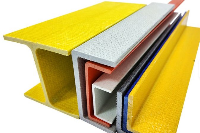
A plant replaces the frame of a 3-cell induced draft cooling tower that has stood since the 1990s. The original galvanized steel columns have thinned to paper at the basin waterline, the fan decks flex visibly under a maintenance technician's weight, and two fill support beams have taken a permanent set. The replacement is specified in pultruded FRP: no recoating cycles, no under-crevice corrosion, and a structure that can be bolted together between two operating cells. Then someone asks the question that decides whether the new frame lasts thirty years or three: what is this structure actually designed for?
A cooling tower frame is not a shed. It carries saturated fill and several tonnes of recirculating water, it houses a rotating machine that sweeps the deck with unbalanced forces several times a second, it is clamped by cold water on the inside and hot sun on the outside, and it presents an open lattice to the wind. This guide works through the load inventory with real numbers, the wind calculation that governs the frame, the fan deck design where vibration matters as much as strength, the material grades that make sense in permanent wet service, and the bolted connections that hold it together in the ACMA LRFD framework.
1. Why a Cooling Tower Frame Is a Distinct Structural Problem
Every condition that shortens the life of a steel structure is present at once in a cooling tower. The lower metre of the frame lives in warm, aerated, biologically active water with chloride levels that climb as the basin cycles up. Above the waterline the members are constantly wet from drift and spray, so they never see the dry cycles that slow atmospheric corrosion. The internal environment is a warm, saturated plume that condenses on every surface when the fan stops. Add the mechanical environment - a multi-tonne fan assembly sweeping the deck with rotating and passing-frequency excitation - and the reason FRP enters the specification becomes obvious: the material does not corrode, does not need coating systems, and its strength does not depend on a paint film staying intact.
A cooling tower frame is designed for three lives at once: the structural life of the members, the corrosion life of the connections, and the fatigue life of everything the fan touches.
The price of FRP is a different design culture. Pultruded profiles are anisotropic - longitudinal properties are several times the transverse values - connections are bearing-type bolted joints rather than welds, and deflection and vibration limits frequently govern before strength does. The sections that follow take each load family in turn and put numbers on it.
2. The Load Inventory: What the Frame Actually Carries
OEM specifications and government guide specifications converge on a consistent set of minimum design loads for cooling tower structures. The table below collects the values that appear repeatedly in procured specifications, alongside the load categories used in the ACMA design framework for pultruded structures.
| Load | Typical specified minimum | Source / convention | Notes for FRP frames |
|---|---|---|---|
| Wind pressure on external surfaces | 30 psf (1.44 kPa) | Recurring OEM/government specification minimum | A floor, not a substitute for a site wind calculation; Section 4 shows the code path can exceed it |
| Fan deck live load | 50-60 psf (2.4-2.9 kPa) | OEM specs (50 psf), federal guide spec (1.9-2.9 kPa), owner specs (60 psf) | Applies to fan deck and hot water basin covers; deflection often governs |
| Fan deck concentrated load | 200 lb (0.9 kN) | OEM specification convention | Position anywhere on the deck; check local bearing under the plate |
| Seismic | 0.3 g (floor) | OEM specification convention | Site-specific design per the governing building code always takes precedence |
| Fill, water and distribution loads | Fluid load (F) category | ACMA load categories | Saturated fill + retained water; a sagging fill support is a process failure, not just a structural one |
| Fan unbalance / vibration | Per drive manufacturer | Gear and fan supplier data | Avoidance of resonance is the primary defence (Section 5) |
| Guard loads | 200 lb (0.9 kN) any direction | OSHA-aligned specification convention | Applies to FRP handrails on the deck; see our handrail guide |
| Ice / wind-on-ice | Site dependent | ACMA load categories (Di, Wi) | Matters for winterised towers; see our winterization guide |
Two habits separate good tower specifications from bad ones. The first is designing only the anchorage for wind and seismic and leaving the structure itself to the vendor - a tower that stays bolted to the foundation while the frame collapses has not been designed. The second is treating the specified minima as the design loads. They are minimums; the governing building code loads at the site frequently exceed them, and the frame should be checked both ways.
3. Fill, Water and Distribution Loads: The Loads That Keep the Air Flowing
The frame's primary job is to hold the fill in the shape the thermal design assumed. Film fill is a light material in the dry state, but in service it is saturated and carries a film of recirculating water; the hot water distribution system adds piping full of water and, on cross-flow towers, a distribution basin holding a shallow depth of water over the fill. For structural purposes these are best handled as a fluid load (F) plus dead load (D) with a stated water depth assumption - for example, a 150 mm distribution basin depth contributes about 1.5 kPa of sustained load across the deck it sits on.
Why the effort matters: fill is a stiffness problem long before it is a strength problem. If a support beam deflects excessively, the fill sheets sag, the sag becomes a short-circuit path for the air, and the tower loses thermal performance while every instrument reads normal. A useful design discipline is to cap long-term deflection of fill support members at a fraction of the fill depth so that no section of the fill can pool water or open a gap - in practice this drives support spacings down and section depths up, and it is the reason fill support grids are checked with the creep characteristics of the resin in mind, not just the initial modulus.
- State the water depth assumption for distribution basins and compute it as fluid load, not as an invisible part of "dead load".
- Check fill support beams for deflection under saturated conditions and long-term (creep) modulus, not just instantaneous.
- Detail drainage so a blocked distribution nozzle cannot load one bay asymmetrically.
- Keep access grating and its clip loads separate from the fill grid - maintenance loads travel on the deck, not through the fill.
4. Wind on an Open Frame: Force Coefficients and Solidity
A cooling tower frame is an open lattice, and ASCE 7 Chapter 29 handles it in the open signs and lattice frameworks table (Figure 29.5-2). The force coefficient depends on the solidity ratio - the ratio of the solid area of members projected on the windward face to the gross area of that face - and on whether the members are flat-sided or rounded:
| Solidity ratio ε | Flat-sided members | Rounded, D√qz ≤ 2.5 | Rounded, D√qz > 2.5 |
|---|---|---|---|
| < 0.1 | 2.0 | 1.2 | 0.8 |
| 0.1 to 0.29 | 1.8 | 1.3 | 0.9 |
| 0.3 to 0.7 | 1.6 | 1.5 | 1.1 |
The force is computed on the solid area of all exposed members projected normal to the wind, with F = qz·G·Cf·Af. Note what the table implies: an almost empty frame (ε < 0.1) attracts the highest coefficient because there is no shielding between members, and the total force is applied with no benefit of shelter. Worked example, using ASCE 7-22 Exposure C (power-law exponent α = 9.5, gradient height 274.32 m), a 45 m/s basic wind speed, Kd = 0.85 for "all other structures", G = 0.85 for a rigid frame, and a tower cell 10 m × 6 m in plan, 7 m tall, with flat-sided members totalling 47.2 m² of projected solid area on the 70 m² windward face:
- Velocity pressure at the 8 m member centroid: Kz = 2.01(8/274.32)2/9.5 = 0.955, so qz = 0.613 × 0.955 × 45² = 1.19 kPa (1185 N/m²).
- Solidity ratio ε = 47.2/70 = 0.67, which falls in the 0.3-0.7 band, so Cf = 1.6.
- Frame force F = 1185 × 0.85 × 1.6 × 47.2 = 76.1 kN.
- The recurring "30 psf on any external surface" specification floor gives 1.44 kPa × 47.2 = 67.8 kN on the same area - the code calculation governs by about 12 percent at this wind speed, and by much more in typhoon or hurricane zones.
- Overturning with the resultant at mid-height: 76.1 kN × 3.5 m = 266.5 kN·m. Against basin water plus structure dead load of roughly 330 kN acting at a 2.5 m lever to the pivot edge, the resisting moment is 825 kN·m - a static stability ratio of 3.1 before any anchorage contribution.
A specification clause that says "design for 30 psf" is a starting point for negotiation, not a substitute for the site wind speed. The two numbers are only equal by coincidence.
For the force coefficients to be valid, wind must be applied in the directions that maximise member forces, and the area Af must be consistent with the coefficient chosen. Casing panels, fan stacks and louvre frames create solid sub-areas that see the solid-sign coefficients instead - they are calculated separately, not lumped into the lattice.
5. Fan Deck Design: Strength Is the Easy Part, Vibration Is Not
The fan deck carries the specified live load (50-60 psf or a 0.9 kN concentrated load, whichever governs locally) plus the fan, gearbox and motor dead loads. Strength is rarely the problem. The 50 psf requirement is 2.39 kPa; a deck beam at 1.2 m spacing spanning 2.4 m between frames carries a factored-pattern line load near 3.2 kN/m including self weight, and a pultruded 152 × 76 mm I-beam at 8 mm wall (second moment of area 920 cm&sup4;, E23 full-section modulus 23 GPa minimum) deflects about 6.6 mm total, 5.9 mm under live load alone - roughly L/410, comfortably inside any L/360-class serviceability target.
Vibration is a different question. The deck is a light, lightly damped floor carrying a rotating machine, and the design intent is to keep the deck's natural frequency clear of the fan's operating speed and its blade-passing harmonics. Using the standard floor-frequency approximation fn ≈ 0.18√(g/δ) - with δ the deflection under the relevant load - the 5.9 mm live-load deflection corresponds to fn ≈ 7.4 Hz:
| Fan speed | Excitation frequency | Ratio fn/ffan | Verdict (target ≥ 1.3) |
|---|---|---|---|
| 200 rpm | 3.3 Hz | 2.21 | OK |
| 300 rpm | 5.0 Hz | 1.47 | OK |
| 360 rpm | 6.0 Hz | 1.23 | Marginal - check as-built frequency, add stiffness or trim mass |
| 480 rpm | 8.0 Hz | 0.92 | Resonance risk - redesign deck framing |
| 580 rpm | 9.7 Hz | 0.76 | Resonance risk - redesign deck framing |
The practical conclusions: match the deck framing to the fan, not the other way round. High-speed fans on wide-spaced light decks are the classic resonance recipe; either stiffen the deck (deeper sections, closer beam spacing, vibration-isolated fan mounts) or select a lower fan speed with a larger fan diameter. The fan deck panel material itself - pultruded plate or moulded FRP grating with the deck loads in mind - is covered in our dedicated fan deck and cooling tower grating guides.
6. Material Grades: EN 13706 in Permanent Wet Service
Structural pultruded profiles are specified to EN 13706, which defines two performance grades - E17 (standard structural) and E23 (enhanced structural). For a cooling tower frame, where members are permanently wet and loads include rotating machinery, E23 is the defensible choice for all primary members:
| Property (EN 13706-3 minimum) | E23 | E17 |
|---|---|---|
| Full-section flexural modulus | 23 GPa | 17 GPa |
| Tensile strength, longitudinal | 240 MPa | 170 MPa |
| Tensile strength, transverse | 50 MPa | 30 MPa |
| Tensile modulus, longitudinal | 23 GPa | 17 GPa |
| Tensile modulus, transverse | 7 GPa | 5 GPa |
| Flexural strength, longitudinal | 240 MPa | 170 MPa |
| Flexural strength, transverse | 100 MPa | 70 MPa |
| Interlaminar shear strength | 25 MPa | 15 MPa |
| Pin-bearing strength, longitudinal | 150 MPa | 90 MPa |
| Pin-bearing strength, transverse | 70 MPa | 50 MPa |
Read the anisotropy in the table as a detailing instruction. The 240 MPa longitudinal tensile strength is real, but the 50 MPa transverse value means a member loaded across its axis - or a web in bearing - is working at a sixth of the headline number. Pin-bearing strength is the property that connections actually use, and it is the reason connection design in the next section is done in bearing terms rather than bolt shear.
Resin and surface: isophthalic polyester is the workhorse for tower frames with a polyester veil surface layer; vinyl ester earns its premium where the basin water chemistry is aggressive or the tower treats contaminated water. Cooling tower circulating water is warm rather than hot - typical design hot water up to roughly 50 °C, cold basin water lower still - which sits well inside the thermal envelope of both resin families, provided the resin's heat-deflection temperature is respected at any locally hot spot such as a pump discharge or heating jacket. Glass content of a structural pultrusion should be at least 60 percent by weight, and the 24-hour water absorption limit of 1.0 percent in the standard is a material acceptance figure, not a licence to ignore end-grain sealing: cut ends are sealed at fabrication because bare glass-rich surfaces wick water along the fibre-resin interface.
7. Connections: Bearing-Type Bolted Joints in the ACMA Framework
Pultruded FRP cannot be welded, so the frame is a bolted structure, and the governing design framework is the ACMA/ASCE Load and Resistance Factor Design (LRFD) pre-standard for pultruded FRP structures - the first design-basis document for pultruded buildings and structures of this kind, with material characteristic values qualified under ASTM D7290 so that different pultruders report properties on the same statistical basis. Its resistance factors are deliberately conservative - independent reliability studies of 350 published bolted-joint tests show the φ factors for pultruded FRP connections sit below the comparable steel values - which is why the published literature repeatedly recommends the same detailing discipline:
- Bearing-type connections designed in shear, bearing, net tension and block shear - not intuition.
- Snug-tight installation torque with washers both sides; high preload in a composite crushes the laminate instead of clamping it. Anti-crush inserts where the joint is structural.
- Standard fasteners are carbon or 316 stainless steel bolts to recognised ASTM grades; FRP fasteners are a niche option for extreme corrosion duty, not the default.
- Hole clearance, edge distance, pitch and gauge follow the connection detailing rules in the design guides and the ASCE/SEI 74 practice for FRP structures - geometry is part of the strength model, not an installation nicety.
A worked sizing example from the deck example above: the beam end reaction is 3.2 kN/m × 2.4 m / 2 = 3.87 kN, shared by two M16 bolts in a clip connection through an 8 mm leg. The nominal bearing capacity of one bolt is d × t × Fp = 16 × 8 × 150 MPa = 19.2 kN - a nominal-to-demand ratio near 10 on service loads, which is the headroom the LRFD resistance factors and long-term creep behaviour are expected to consume. The full design verification - net tension at holes, block shear through the clip, bearing on the supported flange - follows the limit states of the ACMA standard; our separate article on FRP bolted connections works the geometry rules in detail.
In steel you detail connections to the load; in pultruded FRP you also detail them to the laminate - hole clearance, edge distance and snug torque are strength parameters.
8. Bases, Anchorage and Interface Details
The frame transfers its loads into the foundation through base plates and anchor bolts, and three interface details decide whether that transfer survives the tower's environment. First, bearing: the ACMA framework treats base plates and bearings on concrete the same way steel practice does - the bearing stress under the plate is checked against the concrete, and grout brings the plate into full contact. Second, anchorage: anchor bolts should be detailed so the steel of the embedment yields before the laminate crushes or splits, and the anchor design follows the governing concrete code (our seismic restraint guide for FRP tanks covers the anchorage philosophy in depth). Third, galvanic and material separation: stainless fasteners against FRP are benign, but where steel base plates or embedments sit in the wet zone, isolate them with appropriate gaskets or coatings and never let copper-alloy fittings contact the recirculating water circuit of a tower that also serves the structure - copper and its alloys accelerate oxidation chemistry in organic systems and are best excluded from wetted hardware on general principle.
Foundation interface is also where construction tolerance is absorbed. Pultruded members are produced to tight tolerances (straightness on the order of 1.5 mm per metre for typical profiles, cut lengths to a few millimetres), so the base connection detail should provide slot or oversize holes plus shims to take up the foundation's tolerances rather than forcing the frame square on install - forcing induces locked-in bending that shows up later as a warped connection line.
9. Fabrication, Tolerances and QA
Most cooling tower frame problems trace back to four fabrication issues, all of them cheap to prevent at the shop:
- Unsealed cut ends. Every field cut exposes bare glass-rich end grain; seal with the resin system specified for the project before assembly, and re-seal after any site modification.
- Wrong holes. Flame-cut or oversized holes destroy bearing capacity. Holes are drilled to the specified clearance - geometry is part of the ACMA strength model.
- Over-torqued bolts. Torque to snug-tight with washers; impact guns and steel-style torque tables crush legs and webs.
- Grade substitution. E17 substituted for E23 changes modulus by 26 percent - enough to turn a 1.47 frequency ratio into a resonance. Verify grade designation and certificates, not just "FRP".
On inspection, receive profiles against the EN 13706 designation (profile type, resin, grade), check straightness and section dimensions against the standard's tolerance tables, and witness the first assembled bay for fit-up: bolt hole alignment across a bay is the fastest possible audit of the fabricator's drilling jigs. For towers in aggressive water, agree a simple annual inspection scope - connection line check, fill support deflection survey, fan deck walkover - and record it; the failure modes in year 15 are visible in year 5.
10. Specification Checklist and Common Failures
A procurement checklist that captures the points above:
- Primary members to EN 13706 E23, designation and certificates required; glass content ≥ 60 percent by weight.
- Loads: dead + fluid (fill, distribution water, basin), 50-60 psf fan deck live with 0.9 kN concentrated, guard loads, site wind per the governing code (30 psf only as a floor), site seismic, ice where applicable.
- Fan deck checked for natural frequency against the actual fan speed and harmonics; fan vendor data required at design stage, not after delivery.
- Connections designed to the ACMA LRFD framework: bearing, net tension, block shear; snug-tight torque; washers or inserts; 316 SS or carbon fasteners per environment.
- Cut ends sealed; holes drilled; jigs drilled not flame-cut; straightness and dimension tolerances per EN 13706-2.
- Base plates grouted, anchors designed for the governing code, galvanic isolation in the wet zone.
And the recurring failures, ranked by how often they explain a sick tower: fill grid sag from deflection-limited members designed on strength alone; deck resonance on high-speed fans; crushed connections from steel-style torquing; and unsealed cut ends wicking water at the basin waterline. None of them is exotic - all four are specified away in a page.
Request a Design-Supported Quotation
Henan HuanGang supplies pultruded structural profiles to EN 13706 E23, fan deck panels and complete FRP framing packages for cooling tower new-builds and steel-frame replacements, with connection detailing support against the ACMA LRFD framework. Send us your cell plan, fan data and site wind speed, and our engineers will return a load-checked proposal.
Related reading: counter-flow vs cross-flow cooling tower selection, FRP grating platforms in cooling towers and wastewater plants, cooling tower winterization and freeze protection, cooling tower fill maintenance, FRP bolted connection design, and pultruded FRP compression members.
Need help selecting FRP products?
Our engineers answer technical questions free of charge.
Ask an Engineer on WhatsApp