
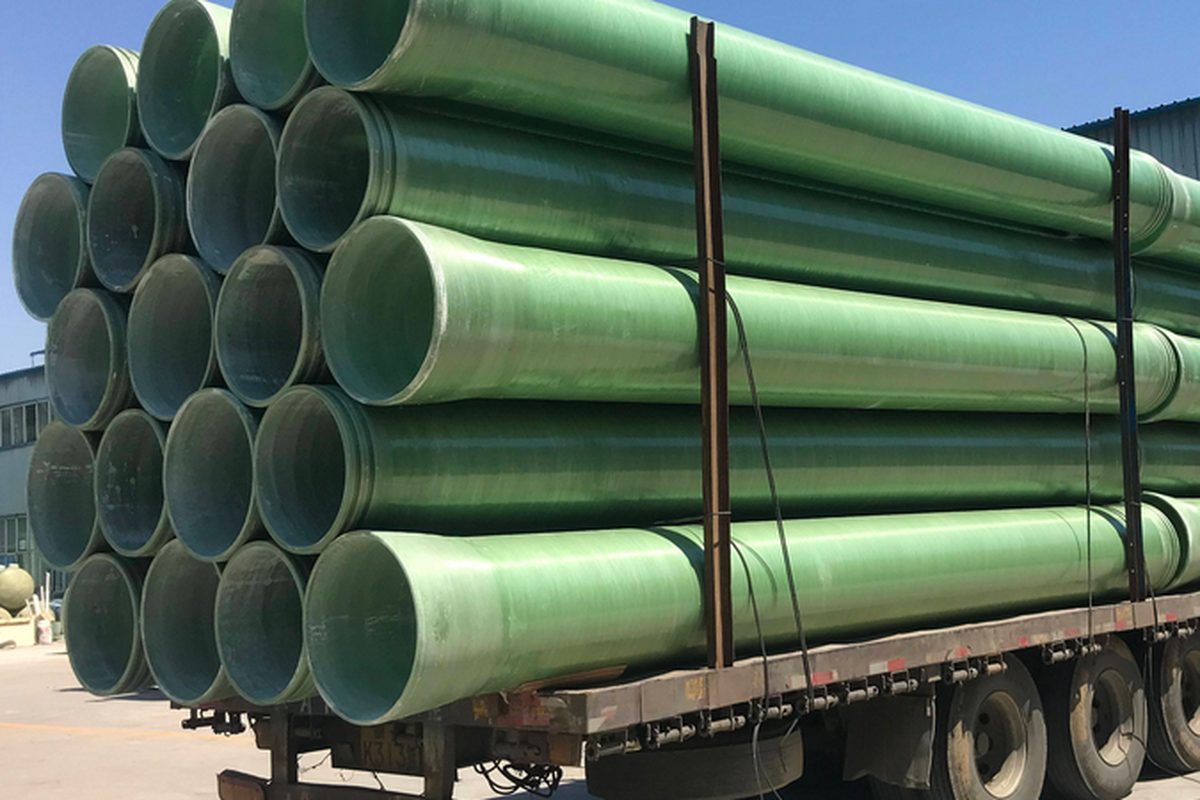
A two-metre FRP duct looks deceptively simple - it is, after all, a tube. But at large diameters the shell is thin relative to its size, the dominant loads are vacuum and self-weight rather than pressure, and the failure mode is elastic instability: the wall buckles inward in lobes and the duct disappears into itself. Fabrication quality and stiffener design, not resin chemistry, decide whether a large duct serves for thirty years or sags and ovalises within one.
1. Wall Thickness by Duct Size and Pressure Class
Unlike pipe, duct design is governed by vacuum/positive pressure class and stiffness rather than hoop stress. Typical starts:
| Duct Diameter | Min Wall (PV1 / +2.5 kPa) | Min Wall (PV2 / -5 to +5 kPa) |
|---|---|---|
| 300-600 mm | 4-5 mm | 5-6 mm |
| 600-1200 mm | 5-6 mm | 6-8 mm |
| 1200-2000 mm | 6-8 mm | 8-10 mm + stiffeners |
| 2000-3600 mm | 8-10 mm | 10-12 mm + stiffeners |
Chemical service shifts liner resin (vinyl ester for acid scrubbers, FGD and brine mist), while structural layers may remain polyester - specify the liner separately from the structural wall. Never scale thickness linearly with diameter; above about 1.5 m, stiffness comes from geometry (stiffeners, corrugation) far more economically than from laminate.
2. Stiffener Rings: The Real Structure
External stiffener rings - usually pultruded or laminated hollow boxes, or sandwich-profile rings - carry the vacuum and bending loads the thin shell cannot. Rules of thumb that hold across vendors: ring spacing tightens as diameter grows (roughly 1x to 1.5x diameter spacing for large ducts); ring stiffness, not ring count, does the work - a deep box ring at 2 m spacing beats three shallow ribs at 1 m; and every ring must be continuous around the circumference with a properly bonded joint at the crown or springline. Longitudinal stiffeners supplement rings at saddle supports and at point loads (access doors, dampers, branch takeoffs). Inside the duct, internal stiffeners are avoided where possible - they collect condensate and debris, and create erosion shadows.
3. Support Spacing and Saddle Design
Ducts are supported on 120-180 degree cradle saddles, width at least 200 mm on large diameters with an elastomer pad between steel and FRP. Support spacing typically runs 2.5-4 m depending on diameter and ring layout, and every saddle must sit on structure that will not settle unevenly - differential support settlement is the classic cause of large-duct ovalisation. Risers and tall vertical runs need guide frames at intervals, not just a base support. Where duct crosses expansion joints in the plant structure, the duct support must not bridge the joint, or building movement loads the duct.
4. Hoods: Loads Beyond Pressure
Hoods and plenums add loads ducts never see: mist eliminator weight and plugging loads, wash-down water, occasional personnel for maintenance access, and the aerodynamic pull of the fan. Design hoods for a maintenance walk load if access is possible, not just operating loads. Large flat panels - hood roofs especially - need sandwich construction or closely spaced ribs; flat FRP panels are the most common sag complaint in the field. Drain the hood: every low point gets a drain nozzle, and mist-carrying service gets washed surfaces sloped to those drains, because standing acidic condensate finds the one unsealed laminate in the panel.
5. Access Doors, Dampers and Branches
| Feature | Design Point | Field Note |
|---|---|---|
| Access door | Bolted FRP or 316 door, full-face gasket, davit or hinge | Reinforce cutout as a nozzle; door frame is a stiffener |
| Branch takeoff | 45-degree sweep, doubler around opening | Sharp tees crack at the crotch radius |
| Damper frame | Isolated frame, thermal gap to hot shell | Steel frame bonded to FRP cracks at the bond line |
| Test ports | Small flanged nozzles, capped | Locate away from stiffeners for probe access |
6. Fabrication QA Hold Points
Quality lives in the process, so specify hold points the fabricator must not pass without evidence: liner cure before structural winding; barcol hardness per joint; spark testing of liner at specified voltage for chemical ducts; stiffener bond verification (visual + tap test); dimensions - roundness within 1 percent of diameter at every shipping splice; and cured lap-joint samples pulled from production periodically. Joint style matters for field assembly: butt-and-strap joints need skilled laminators and clean conditions on site; belled or flanged splices assemble faster and forgive weather. Choose the joint style when purchasing, not when the crew is standing in the rain.
7. Installation: Setting, Alignment and Sealing
Set ducts on their saddles with the roundness you bought them with - pulling a shipping oval straight with the support bolts damages the laminate invisibly. Align splices with a 2-3 mm even gap, laminate or bolt per procedure, and respect cure time before pulling vacuum on the system. Test before insulation and cladding go on: a soap-solution or pressure-decay test finds the six leaks that the insulated system would hide for years. And commission the fan gently - a full-vacuum start on an unproven large duct is the ultimate field test nobody wants to be part of.
8. Maintenance Points
Walk the duct route annually: check saddle pads for crush, look for white crazing at stiffener bond lines (an early stiffness-loss signal), verify drain nozzles actually drain, and re-torque access doors after the first thermal cycles. Interior inspections at shutdowns should photograph stiffener crowns and drain valleys - the two places problems start. A duct that is dry, round and drained stays a duct; one that ponds, ovalises and leaks becomes a rebuild project.
Related reading: FRP ventilation duct installation specifications, FRP flue and chimney liners, and our FRP ventilation ducts.
Need help selecting FRP products?
Our engineers answer technical questions free of charge.
Ask an Engineer on WhatsApp