
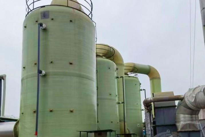
A vertical FRP storage tank earns its place wherever footprint is tight and gravity is your friend: process liquids, chemicals, water storage, dosing and mixing all sit naturally in a tall cylinder that occupies a few square metres of plant floor. But vertical tanks load their foundation and anchorages very differently from horizontal tanks — an empty tank in wind is a sail on a mast, and a full tank is a column of liquid that must never move.
This guide covers the specification and installation decisions specific to vertical FRP storage tanks: foundations, wind and seismic anchorage, shell proportions, accessories and the field procedures that keep a tall composite vessel safe.
1. When a Vertical Tank Is the Right Shape
- Footprint: the same volume in a fraction of the plan area — the usual reason.
- Head for pumps and drains: stored liquid level provides natural static head.
- Mixing and settling: tall columns suit agitators, reaction and clarification duty.
- Limits to watch: very tall slender tanks need more anchorage and stiffer shells; access for internal cleaning gets harder with height.
2. Shell Proportions and Construction
Vertical FRP tanks are filament-wound cylinders with a domed or flat top and a flat or conical bottom. Two proportions matter:
- Height-to-diameter ratio (H/D) — typically between 1 and 2.5 for standard designs; beyond that, wind overturning and wall buckling start to drive the wall thickness rather than the liquid head.
- Wall build-up — hoop strength for the liquid head increases toward the bottom, so large tanks are often wound with a stepped or tapered wall. Confirm the wall schedule against the liquid density, not just the volume.
Our FRP vertical storage tanks are wound to the liquid's specific gravity, temperature and local wind/snow loads.
3. Foundations: Flat, Level and Fully Supported
- Concrete pad with a flatness tolerance — commonly about 5 mm across the diameter — so the tank bottom bears evenly and does not rock on high spots.
- Full bottom support: never let a flat-bottom FRP tank sit on its rim or on point supports; use a full concrete pad, or a compacted granular bed for small tanks, with a vapour barrier where ground moisture is an issue.
- Slope for drainage away from the pad, and keep the pad above flood level.
4. Wind and Seismic Anchorage
An empty tank is the worst wind case: low weight, large sail area. The design must check overturning at the base for the empty condition:
| Design input | Why it matters |
|---|---|
| Basic wind speed (location) | Sets the wind pressure on the projected shell area |
| Exposure and height | Open sites and tall tanks multiply the load |
| Seismic zone | Sloshing and base shear in seismic areas |
| Anchor bolt layout | Lugs spaced around the base, corrosion-protected, load-spreading plates |
Hold-down lugs are laminated into the base at the factory; field crews must use the specified bolt size, torque and plate arrangement — undersized washers on anchor bolts are a classic cause of local crushing.
5. Accessories and Penetrations
- Manways — side manway for cleaning and an optional top manway; each penetration is reinforced locally and must be included in the drawings, not cut in the field.
- Nozzles — flush or protruding, sized and reinforced for the connected pipe; more than two penetrations in one course need a layout review.
- Venting — free-breathing or pressure/vacuum vent sized for fill and withdrawal rates; an unvented tank can collapse under vacuum when pumped out fast.
- Level and instrumentation — external level gauges avoid internal penetrations; stilling wells for ultrasonic probes.
- Agitators: mount heavy agitators and motors on a separate support structure, not on the tank dome — vibration and torque fatigue the laminate.
- Insulation and heat tracing where contents need temperature control — verify the insulation weight and wind load on the shell with the manufacturer.
6. Field Installation Sequence
- Set the tank on the cured pad; check level across the base before anchoring.
- Anchor per the lug layout; torque gradually in a circular pattern.
- Connect piping with a flexible joint at the nozzle so settlement and thermal movement do not load the tank.
- Fill staged with water (25/50/75/100 %) while watching the pad, the anchors and the shell for movement or distortion.
- Hold the test level, inspect joints and nozzles, then empty if not commissioning immediately.
7. In-Service Inspection
- Annual external check: UV exposure of the gelcoat, anchor tightness, gasket condition at nozzles.
- Periodic internal inspection with lighting: look for liner crazing, scratches and any exposed fibres — small liner damage is repairable, deep attack is not.
- Re-torque anchor bolts after the first year and after any seismic event.
8. Specification Checklist
| Parameter | Example entry |
|---|---|
| Capacity and dimensions | 50 m³, DN 3000 × H 8000 |
| Contents | 30 % HCl, SG 1.15, 40 °C |
| Resin / liner | Vinyl ester, chemical-grade liner with veil |
| Wind / seismic | 45 m/s basic wind, Zone 2 seismic |
| Accessories | Side manway, 4 nozzles, P/V vent, anchor lugs |
9. Common Specification Mistakes
- Sizing the wall on water head when the stored chemical is denser or hotter.
- Forgetting the empty-tank wind case in anchorage design.
- Mounting agitators on the dome and fatiguing the laminate.
- Cutting extra penetrations on site instead of reinforcing them at the factory.
For the horizontal alternative and general tank transport and erection, see the FRP tank transport and installation guide; browse the whole FRP storage tank range for horizontal, vertical and underground vessels.
Need help selecting FRP products?
Our engineers answer technical questions free of charge.
Ask an Engineer on WhatsApp