
Every plant that corrodes steel pipe racks has the same second problem waiting: the cable tray. Galvanised steel ladder rack loses its zinc in FGD zones, coastal utilities, chlorination buildings and wastewater plants within years, and then the maintenance answer - paint the tray in place, energised and loaded - costs more than the tray did. Pultruded FRP cable tray was developed for precisely this loop, and once spans and fixings are understood, it is the cheaper system by total life cost nearly everywhere aggressive.
1. Where FRP Tray Wins, and Where It Does Not
FRP ladder and tray excel where humidity, chlorides, acid mist or salt spray destroy coatings: wastewater treatment, desalination, FGD ducting routes, plating shops, pulp and paper, offshore splash zones and coastal substations. It also wins around electrified rail and where electrical isolation from earthed structures is wanted. Where steel still wins: physically abused locations (forklift routes without protection), very long unsupported spans beyond pultruded capability, and areas where continuous extreme heat (steam leaks, flue proximity) sits above the tray. A honest selection starts with the environment map, not the catalogue.
2. System Types: Ladder, Ventilated Tray, Solid Tray, Trench
| Type | Best For | Notes |
|---|---|---|
| Ladder rail | Power cable runs, long spans | Best ventilation; cables cleated to rails |
| Ventilated tray | Instrument and control cabling | Supports small cables with some airflow |
| Solid tray / cover | Dust, droppings, falling-object zones | Covers add load; derate spans accordingly |
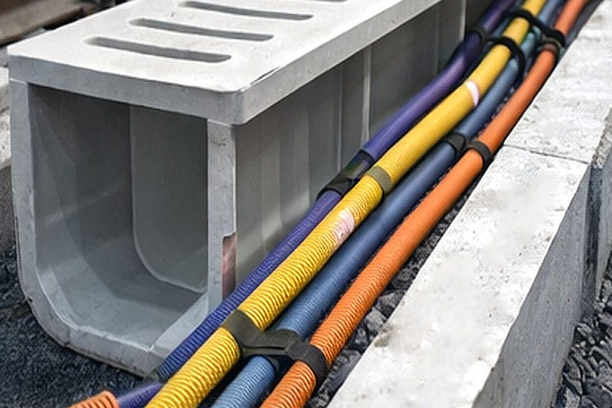
| Trench / duct systems | Buried or flush routes, road crossings | FRP trench covers combine tray and structural cover |
Widths run 100 to 900 mm standard, depths 50 to 150 mm. Power and instrument segregation follows the electrical design rules of the project (spacing or barriers) - the tray material does not change segregation requirements.
3. Load Classes and Span Tables
Tray is rated by load class at a reference span, typically 3 m, with test loads including a safety factor. Practical rules: standard pultruded ladder spans 3 m comfortably with power cable loads; instrument tray on 2-3 m supports; covers and heavy cable concentrates reduce allowable span - check the manufacturer's loaded-span table rather than the bare-tray figure. Supports are the same galvanised problem as the tray it replaces, so the complete answer is FRP tray plus FRP or 316 supports; mixing one FRP component into a steel system just moves the corrosion to the brackets.
4. Fittings and System Completeness
A tray system is judged at its fittings: horizontal and vertical bends, tees, crosses, risers and reducers all exist in pultruded FRP, either factory-made or assembled from straight lengths with splice plates. Factory fittings keep radius and cable-bearing geometry correct; field-fabricated bends from cut-and-bolted straight sections are acceptable for power tray but create sharp cable-bearing corners on instrument work. Specify splice plates at every joint (two per joint minimum, four on loaded runs), expansion splice slots on long outdoor runs, and end plates where the run terminates into panels or cable boxes.
5. Fixings, Supports and Hardware
Hardware is where FRP tray systems quietly fail - not the tray. Use 316 stainless or GRP bolts throughout; never mix galvanised hardware into the system. Cantilever brackets, trapeze hangers and floor supports exist in pultruded FRP profiles, which keeps the whole corrosion loop broken. Torque practice follows the bolted-connection rules for composites: snug plus quarter-turn, washers both faces, and no impact guns into the tray sides. Where tray crosses expansion joints in structures, support both sides independently and provide a slotted splice.
6. Earthing and Lightning: Handle It Deliberately
FRP tray is non-conductive - an advantage for isolation, a change for earthing design. Continuous earth conductors (bonding cable laid in the tray, or a dedicated earth strip) replace the earth continuity that steel tray provided by default. Lightning protection and fault-current paths must be engineered explicitly with the electrical designer; the good news is that non-conductive tray also removes induced circulating currents and the earth-fault paths through supports that steel systems fight with isolation pads. Document the earthing arrangement on the tray layout drawings so inspection teams see a designed system, not an omission.
7. Installation Practice
| Step | Rule |
|---|---|
| Setting supports | Span per loaded-span table; brackets plumb; no tray carries its own cantilever past 150 mm |
| Tray erection | Straight lengths joined with splice plates; fittings bolted with full hardware set |
| Cable pulling | Sheave sizes and sidewall pressure per cable spec - FRP surface is smooth, cleats still required |
| Cutting on site | Carbide blade, sealed cut edges on exterior-grade product |
| Handover | Walk the run: every splice plated, every support bolted, covers clipped |
8. Lifecycle Cost Check
The comparison that closes projects: galvanised tray replaced or recoated at years 8-15 in aggressive service versus FRP tray untouched, with support replacement to match. Add the maintenance access cost (scaffolding, permits, outages) that steel recoating demands and FRP avoids, and the case is usually closed before the first repaint would have been scheduled.
Related reading: FRP cable conduit vs PVC vs steel, FRP handrail systems, and our FRP cable trench systems.
Need help selecting FRP products?
Our engineers answer technical questions free of charge.
Ask an Engineer on WhatsApp