
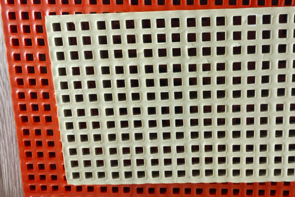
Molded FRP grating leaves the factory as a fully sealed, corrosion-proof panel. The moment it is cut, notched or drilled on site, that protection depends entirely on workmanship: a raw, unsealed cut edge wicks resin and moisture, and a poorly clipped panel flexes, Fatigues its bearing bars, and rattles loose within a season. The good news is that grating fabrication is straightforward once a few rules are understood.
1. Tools and Preparation for Cutting
Both molded and pultruded panels cut cleanly with standard power tools. Use a carbide-tipped circular saw or a diamond grit blade; for curves and notches around column bases, a jigsaw with a coarse tungsten-carbide blade works well. Support the panel close to the cut line on two timber bearers so the offcut cannot pinch the blade or drop suddenly. Mark the cut with a felt pen on the surface, and - importantly - mask the line with tape when a cosmetic top surface matters, because fiberglass dust embeds in gel coat. Cutting generates fine glass dust: set up outdoors or with mechanical extraction, and wear a fitted P2/N95 respirator, goggles and gloves as standard practice.
2. Cutting Step by Step
Plan the layout so that factory-finished edges face walkway edges and open sides, and field-cut edges land on internal, supported runs. Cut with the bearing bars perpendicular to the supports (this rule seems obvious and is still the most common layout error). Feed the saw at a steady moderate rate - forcing the blade melts resin and glazes the cut. Leave 5-10 mm clearance at columns, pipes and equipment for thermal movement and fabrication tolerance; the gap is later covered by edge nosing or sealant beads. For pultruded grating, remember the I-bars run one way only: measure bearing direction before the first cut, not after.
3. Sealing Cut Edges
| Edge Condition | Treatment | Where Used |
|---|---|---|
| Factory panel edge | None required - fully sealed at manufacture | Panel perimeters as delivered |
| Straight field cut | Brush two coats of compatible resin (isophthalic or vinyl ester to match panel) | All exposed straight cuts |
| Walkway edge / open side | Solid GFRP edge nosing or sealed with resin + silica filler, mechanically fixed | Platforms, walkway borders, stair stringers |
| Notch / cutout around pipe or column | Resin brush coat into the concave corner; radius corners when marking | Every cutout - corners are crack starters |
| Drilled hole for clip | Resin droplet on hole wall | All site-drilled fixing holes |
The resin must chemically match the panel - never seal a vinyl ester panel with cheap polyester resin, because the cut edge is where aggressive media attacks first. Cure the sealant fully (typically 30-60 minutes tack-free) before the panel goes into service or gets walked on.
4. Clip Types and Fixing Patterns
Grating clips are small, cheap and absolutely load-bearing in the design. The standard family uses four types: the A clip (hook-and-clamp for square openings on molded panels), the B clip (for rectangular mesh openings), the C clip (a simple Z-type retainer for edges), and the D/lifting clip used with panels that are regularly removed for access. Typical practice:
| Panel Size | Minimum Clips | Pattern |
|---|---|---|
| Up to 1000 x 2000 mm | 4 | One per corner |
| 1000 x 3000 mm and larger | 6-8 | Corners plus mid-edge at 1.0-1.5 m |
| Panels subject to uplift / vibration | 8+ | Every 500-700 mm on all bearing edges |
| Removable access panels | 4 (D clips) | Corners, tool-operated |
Fix clips with M8 stainless or FRP fasteners into the supporting steel; where the substructure is also FRP, use the manufacturer's clip bolts with oversized washers and tighten snug-plus-a-quarter-turn - over-torque crushes the mesh. On rooftop and coastal installations, specify 316 stainless or GRP hardware throughout.
5. Bearing Rules: Spans, Overhangs and Load Direction
Molded grating bears on its bars in one direction only, so supports must run perpendicular to the bars. Keep bearing length at least 30 mm on each support (50 mm for pultruded and for heavy traffic areas). Design span from the load table, not from habit: 38 mm molded grating at 1 m span typically carries a 5 kN point load with ample reserve, but the same panel at 1.5 m span concentrates stress where wheels and footsteps land. Never cantilever a panel more than 50 mm past its last support - the classic failure is a grating sheet propped on a channel flange with 200 mm hanging over air.
6. Working Around Openings, Risers and Equipment
Cutouts for pipes, valve stems and column penetrations should be marked with radiused corners (a 25 mm radius minimum) to eliminate crack-starting notches, then resin-sealed into the concave corners. Where walkways pass ducts or vessels, close the gap between grating edge and equipment to less than 10 mm or fit a kickplate - a 25 mm toe board fixed to the nosing satisfies most platform safety codes and stops tools migrating. Around frequently opened equipment, divide the area into small removable panels rather than one large one: a 4-clip panel two people can lift is a maintenance asset, a 40 kg sheet is an accident.
7. Stair Treads and Nosing
Use dedicated grating stair treads with pre-bonded anti-slip nosing (grit surface, often a contrasting yellow). Treads bear 30-50 mm into the stringer channel and are fixed with two clips or bolted carriage bolts per end. Check going and rise against the staircase spec before ordering - grating cannot be trimmed by much without losing the nosing overhang. On towers and offshore structures, specify treads with the integral nosing plus a mid-span support where the clear width exceeds 900 mm.
8. Common Mistakes and Corrective Actions
| Mistake | Consequence | Fix |
|---|---|---|
| Unsealed cut edges left exposed | Fibre bloom, wicking, edge crumble within 1-3 years | Resin-seal all cuts, add nosing at open edges |
| Panels laid unclipped | Rocking, noise, bars fatigue at bearing line | Fit clip set per table; drill and resin holes |
| Bars run parallel to supports | Mesh bears on rods, collapses under load | Re-lay panels; verify bearing direction before cutting |
| Sharp-cornered notches | Crack initiation at cutout | Re-cut with radiused corners and seal |
| Oversized gaps at equipment | Toe and tool traps, audit findings | Fit filler strips or kickplates |
9. Handover Checklist
Before sign-off, walk every line: all cut edges sealed and cured; nosing fixed on every open edge; clip count and pattern per panel verified; every panel bears 30 mm or more on both supports with no significant cantilever; cutouts radiused and sealed; stair treads clipped with nosing intact; removable panels actually removable with the specified tool; and no panel rocks underfoot anywhere on the deck. Photograph key areas and file the clip schedule with the as-built drawing set - ten minutes of paperwork that saves the next maintenance shutdown.
Related reading: FRP grating load tables explained, molded vs pultruded grating, and our walkway and stair tread grating.
Need help selecting FRP products?
Our engineers answer technical questions free of charge.
Ask an Engineer on WhatsApp