
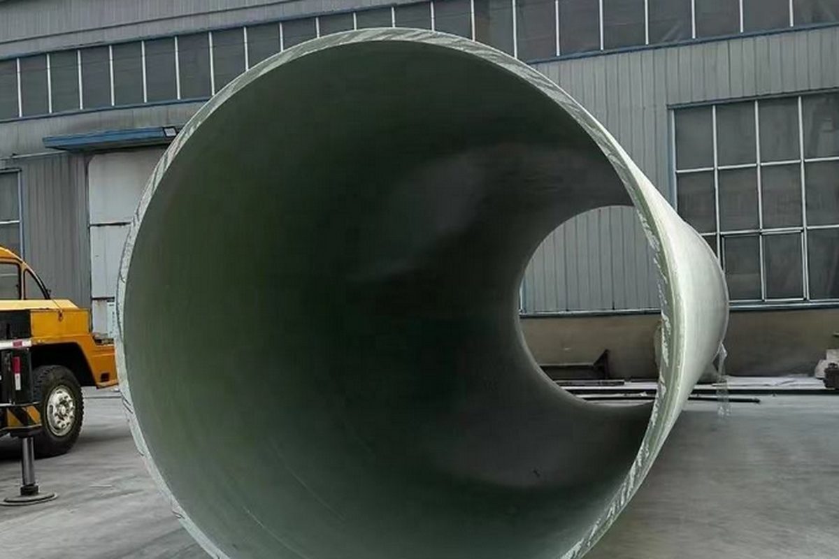
An FRP pipe can be manufactured to a perfect laminate and still fail in service if its support system is wrong. Fiberglass pipe has roughly one-tenth the bending stiffness of steel and does not plastically dent the way steel does - it simply accumulates strain at hard points until the liner crazes or the wall cracks. Support design is therefore not a copy-paste from the steel piping spec: spans, saddle geometry and restraint placement all need to be engineered for the composite.
1. Why FRP Support Design Is Different
Three properties drive the difference. First, modulus: filament-wound FRP at 20-30 GPa is far more flexible than steel, so spans must be shorter to control sag and beam stress. Second, creep: under constant bending stress, FRP deflection increases with time, so long-term spans are set below short-term ultimate values. Third, local bearing sensitivity: a narrow steel rack beam pressing on a round FRP pipe creates a line load the laminate was never designed for. All three are solved by the same vocabulary - shorter spans, wider contact, and saddles that spread the load.
2. Recommended Support Spans by Diameter
The table below gives conservative field spans for water-filled filament-wound pipe (PN10 or lower, 20 C). Always confirm against the manufacturer's span tables for the actual pressure class, specific gravity of the fluid and temperature, because allowable span falls as temperature rises.
| Nominal Diameter (DN) | Typical Continuous Span (m) | Max at Valves / Heavy Fittings |
|---|---|---|
| 50-80 | 2.0-2.5 | Support each side of mass |
| 100-150 | 2.5-3.0 | Support each side of mass |
| 200-300 | 3.0-3.5 | Support each side of mass |
| 350-500 | 3.5-4.0 | Nearest supports within 1x DN |
| 600-900 | 4.0-4.5 | Nearest supports within 1x DN |
| 1000+ | 4.5-5.0 | Engineer-verified per run |
For vacuum service, sloped lines that must drain, or temperatures above 50 C, reduce the tabulated span by 20-30 percent. When a line runs mostly empty but is occasionally hydrostatically tested, the test condition often governs - check the filled weight, not just the operating weight.
3. Saddles, Wear Pads and Contact Geometry
Wherever the pipe rests on structure, use a 120-degree saddle rather than a flat beam or a thin strap. Saddle width should be roughly half the pipe diameter with a minimum of 100 mm for DN200 and above, and the saddle radius should match the pipe od within a few millimetres - an oversized saddle bears only on its toes. Between saddle and pipe, fit an elastomer wear pad 3-6 mm thick; it evens out contact, allows a small amount of differential movement, and prevents abrasion of the outer surface as the pipe breathes with pressure cycles. U-bolts, where unavoidable, must be loose with a liner sleeve: never torque a bare steel U-bolt against FRP.
4. Guides, Anchors and Restraint Logic
Above-ground FRP lines follow the same restraint vocabulary as steel - anchors fix a point in all six degrees of freedom, guides allow axial sliding but stop lateral movement - but the placement logic differs. Because FRP thrust blocks at bends are weaker, restraint at direction changes is usually provided by anchoring the adjacent support structure rather than the pipe itself. Space guides at 2-3 span intervals between anchors so the pipe stays straight and lateral buckling cannot develop. Every riser and every heavy in-line device (valves, strainers, flow meters) gets its own independent support; never let a valve hang its weight on the pipe wall.
5. Thermal Movement: Calculating and Accommodating
FRP expands about 20-25 x 10-6/K - roughly twice steel. A 60 m run warming by 30 K grows about 40 mm. That movement must go somewhere. The design hierarchy is:
| Solution | Best For | Notes |
|---|---|---|
| Natural flexibility (L-bends, Z-bends) | Short runs with geometry available | Verify leg length absorbs the growth without overstress |
| Expansion loops | Long straight racks | Loop leg length set from span, diameter and delta-T |
| Bel type couplings / spigot-socket joints | Buried and above-ground GRP | Joint takes angular and axial movement; retain pipe at each side |
| Bellows expansion joints | Confined plant rooms | Must include proper main anchors either side |
Whichever solution is chosen, movement must be calculated, not guessed, and the guide/anchor layout must be consistent with it. A line that is over-anchored cannot grow and will buckle or shear a fitting.
6. Supporting Valves, Flanges and Concentrated Masses
Isolate valve and flange mass with supports immediately adjacent on both sides - within one pipe diameter for DN350 and below. Butterfly valves with gearboxes and actuated assemblies are particularly heavy for their size; check the acting weight including the actuator, not just the bare valve. At vertical risers, support from below with a base elbow resting on a saddle, or clamp the riser at floor slabs - do not let the entire column load pass through a single glued joint.
7. Common Field Mistakes and How to Correct Them
| Mistake | Consequence | Correction |
|---|---|---|
| Pipe laid directly on steel rack beam | Line-load abrasion, liner wear, eventual weep | Retrofit 120-degree saddle plus wear pad |
| U-bolt tightened against pipe | Local crushing, stress crack at clamp line | Loosen, add sleeve and rubber liner, hand-tight only |
| Supports spaced per steel table | Progressive sag, creep deflection, joint weep | Re-space to FRP span table |
| No allowance for thermal growth | Bowed line, buckled loop, sheared fitting | Add loop or bel couplings, re-layout guides |
| Valve weight carried by pipe | Cracked hub or flange root | Independent support both sides of valve |
Most corrections are inexpensive if caught at pre-commissioning walkdown; after hydrotest, the same corrections require draining, repair and retest.
8. Pre-Commissioning Support Walkdown Checklist
Before hydrotest, walk the line and verify: every support exists at the tabulated spacing; every saddle carries a wear pad; no bare steel contacts FRP; guides allow axial slide (slide surfaces clean, gaps correct for temperature at installation); anchors are rigid and aligned; every valve and heavy fitting is independently supported; risers are held at slabs; expansion provisions match the calculated growth; and nothing - scaffolding, cable tray, temporary lines - has been hung from the pipe. Photograph each support location; the record becomes the baseline for future maintenance rounds.
Related reading: FRP pipe installation and pressure testing, choosing FRP pipe diameter and wall thickness, and our filament-wound FRP pressure pipe.
Need help selecting FRP products?
Our engineers answer technical questions free of charge.
Ask an Engineer on WhatsApp