
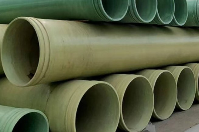
A filament-wound FRP pipe leaves the factory with a precisely controlled laminate, but its service life is largely decided on site. Field failures of buried and above-ground fibreglass piping systems are far more often traced to poor bedding, careless jointing, wrongly spaced supports or an over-aggressive pressure test than to a defect in the pipe wall itself. The pipe is a flexible composite with roughly one-tenth the stiffness of steel, and it punishes installation mistakes that a steel pipe would shrug off. This guide walks through the installation sequence for FRP/GRP piping — handling, bedding, jointing, supports and field testing — with the numbers and acceptance criteria engineers actually need.
Before installing, you should already have decided diameter, wall thickness and pressure class; our pipe sizing guide and GRP pipe specification guide cover that stage. This article assumes the pipe has been specified correctly and focuses on getting it into the ground safely and proving it afterwards.
1. Handling and Storage Before Installation
FRP pipe is strong in its designed direction but vulnerable to point loads and impact. Follow these rules from the moment the pipe arrives:
- Lift large-diameter pipe with wide slings or a spreader bar, never chains or wire ropes that concentrate load on a small contact area. Use the lifting lugs fitted at the factory where provided.
- Store pipe on timber cradles with a support angle of at least 120° at the bottom, spaced closely enough to prevent sagging and ovality. Do not stack so high that lower layers deform; keep stacks stable and chocked.
- Keep pipe off bare ground, out of vehicle traffic, and shaded if it will sit for more than a few months — most FRP systems carry UV protection, but extended exposure degrades the resin-rich surface.
- Protect bell ends, flanges and spigots with the factory caps or covers; a damaged joint face is a leak waiting to happen.
2. Trenching, Bedding and Backfill for Buried Lines
Buried GRP pipe is a flexible pipe: it needs the surrounding soil to carry the load. The trench and embedment, not the pipe wall alone, are the structure. Key rules:
- Trench width should allow proper compaction beside the pipe — typically the pipe outside diameter plus 400-600 mm total working space, and never so narrow that sidefill cannot be compacted.
- The trench floor must be level and free of rocks; use a 100-150 mm layer of selected granular bedding and create shaped depressions at bell joints so the bells are not point-loaded.
- Place and compact sidefill in layers of 150-300 mm up to at least the springline (pipe mid-height) before any heavy compaction over the crown. The haunch area — the zone under the pipe sides — is the most commonly neglected and the most important.
- Use selected granular material with a maximum particle size of about 20-25 mm next to the pipe; backfill above the crown with care until there is at least 300 mm of cover before allowing machinery over the pipe.
The stiffness class matters here. GRP pipe is rated by nominal ring stiffness — SN2500, SN5000 or SN10000 (N/m²) — measured by parallel-plate loading. A higher SN pipe resists ovality better under poor bedding, while a low-SN gravity pipe demands disciplined sidefill compaction. A common design limit for buried GRP is a long-term ring deflection of 5% of the internal diameter, which is why deflection is measured after backfill (see Section 8).
3. Joining Methods and When to Use Each
| Joint type | Typical sizes | Advantages | Limitations |
|---|---|---|---|
| Bell-and-spigot adhesive joint | DN50 - DN600, pressure classes | Fast, clean, no bulky external laminate; the standard factory joint for filament-wound pressure pipe | Requires careful surface prep and full cure before backfill; not for frequent dismantling |
| Butt-and-strap field laminate | Large diameters, gravity lines, repairs | Joins any diameter on site; also used for repairs and branch connections | Wet lay-up needs clean conditions, trained labour and cure time; quality depends on the laminator |
| Flanged joint | All sizes to equipment | Dismantlable; ideal at pumps, valves, tanks and tie-ins | Gasket selection and bolt torque are critical; heavier and costlier per joint |
| Elastomeric seal (gasket) joint | Buried gravity and low-pressure lines | Quick to assemble, tolerates slight misalignment, no cure time | Requires restraint/thrust blocks where internal pressure can push joints apart |
Whichever joint you use, keep the jointing area clean and dry — dust, moisture and rain are the main causes of adhesive joint failure.
4. Adhesive Joint Procedure, Step by Step
The bell-and-spigot adhesive joint is the workhorse of FRP pressure piping. A reliable field joint follows this sequence:
- Dry-fit and mark. Push the spigot into the bell without adhesive and mark the full insertion depth on the spigot. Check the joint pulls up square and true.
- Prepare the surfaces. Abrade the bonding areas of both spigot and bell with abrasive paper or pad (about 80-120 grit) to remove the resin-rich gloss, then wipe dust off with a clean dry cloth.
- Solvent wipe. Wipe both abraded surfaces with acetone or MEK on a lint-free cloth and allow to flash off completely. Do not wipe with oily rags or touch the surfaces afterwards.
- Mix and apply adhesive. Mix the two-part epoxy or polyester jointing adhesive strictly to the manufacturer's ratio and pot life. Apply a uniform coat to the full bonded length of the spigot and inside the bell.
- Insert. Push the spigot fully home to the depth mark using a puller or jacking frame on large diameters, keeping the pipe in line. Wipe off the excess adhesive bead that squeezes out — a clean internal bead is a sign of full coverage.
- Support and cure. Keep the joint undisturbed and supported. Cure time depends on temperature: typically 6-8 hours to handling strength and about 24 hours to full strength at 25°C, roughly doubling below 15°C. Do not backfill, pressure test or pull the pipe until the adhesive has reached handling strength.
Adhesive jointing is a temperature-sensitive chemical process, not a mechanical one. Below about 10°C most standard adhesives cure too slowly to be reliable, and above 35°C pot life collapses. If the site temperature is outside the comfortable band, use a winter or summer grade adhesive from the system supplier — and record the batch and ambient temperature in the joint log.
5. Above-Ground Supports: Spacing, Clamps and Restraints
Above-ground FRP lines need more support than steel because the modulus is lower. The table below gives indicative support spacings for water-filled, uninsulated GRP pressure pipe at moderate temperature; these are a starting point and must be confirmed against the pipe stiffness class, temperature, and the manufacturer's span tables.
| Nominal diameter | Indicative support spacing | Notes |
|---|---|---|
| DN50 - DN80 | 1.8 - 2.2 m | Small bores are flexible and sag visibly if spans are too long |
| DN100 - DN150 | 2.2 - 2.8 m | Standard chemical process range |
| DN200 - DN300 | 2.8 - 3.5 m | Confirm against SN class and contents weight |
| DN400 and above | 3.5 - 4.5 m | Large bores are stiffer but heavy; verify with the supplier |
Support hardware matters as much as spacing:
- Use wide-band clamps with an elastomer or rubber liner and a contact angle of roughly 90-120°; never clamp bare FRP in a narrow steel U-bolt, which crushes the wall at the contact line.
- Tighten clamps enough to hold the pipe without squeezing it oval; over-torquing a clamp is a common cause of local stress cracking.
- Anchor the pipe at changes of direction, at tees and at equipment nozzles so thermal and pressure loads do not push joints apart; put guides near anchors and allow the line to expand in controlled straight runs.
- Filament-wound GRP has a low axial coefficient of thermal expansion relative to plastics — typically on the order of 10-18 × 10-6/°C — but a 50°C process swing on a 30 m straight run still moves the pipe roughly 15-25 mm. Design expansion loops, offsets or expansion joints instead of restraining the movement rigidly.
6. Pressure Testing: Pressures, Sequence and Acceptance
Field pressure testing proves the joints and the installed system, not the pipe wall — the pipe was already proof-tested at the factory. Common practice for FRP systems:
| Step | Action | Acceptance |
|---|---|---|
| Fill and vent | Fill slowly from the lowest point with all high points vented; bleed trapped air completely | Stable fill, no leaks at zero pressure |
| Ramp up | Pressurise in steps of roughly 25% of test pressure, holding briefly at each step | No weeping at joints during the climb |
| Test pressure | Reach test pressure of 1.5× design pressure, but never above the lowest rated component (flange, valve, gasket) in the loop | No visible leaks |
| Hold | Hold test pressure for at least 30 minutes after stabilisation, topping up as needed | No pressure decay after top-up; joints dry |
| Depressurise | Reduce slowly to working pressure and inspect all joints and supports | Record on the test chart |
Do not expect a bonded FRP system to behave like a welded steel line: slight pressure relaxation from pipe expansion and trapped air is normal during the first minutes, which is why the hold starts after stabilisation. If a joint weeps at test pressure, depressurise, cut out and remake the joint — patching a pressurised adhesive joint almost never holds.
Never pneumatic-test an FRP system — or any piping system — without a written procedure and controlled staging. Compressed air stores enormous energy: a failed joint or fitting can turn the pipe into a projectile. If a pneumatic test is unavoidable, keep test pressure low, cordon the area, and follow the project's specific hazard procedure to the letter.
7. Deflection and Leak Checks for Buried Gravity Lines
Non-pressure sewers and drainage lines are tested differently from pressure pipe, because the design concern is ovality and infiltration, not hoop stress:
- Deflection test. After final backfill and compaction, verify that the pipe has not deformed beyond its design limit — commonly 5% of internal diameter. A simple method is pulling a rigid mandrel through the line: for a 5% limit the mandrel diameter is 95% of the pipe internal diameter. Laser profiling is used on larger diameters. If the mandrel binds, locate the oval section, excavate, recompace and retest.
- Water/air tightness. Gravity systems are commonly tested to standards such as EN 1610, using a water test held for 24 hours or a controlled air test, with allowable loss limits set by the standard and the pipe diameter.
- Run the deflection check after the leak test and before handover, and keep the results with the as-built record.
8. Damage, Repairs and the Hammer Test
Before backfilling or commissioning, walk the line and tap the pipe lightly with a non-marring hammer or tool. A sound laminate rings; a dull, thudding response indicates delamination or impact damage, and the area should be marked for repair. Shallow surface damage (scratches, gouges through the gel coat) is repaired by abrading, solvent wiping and recoating with matching resin. Deeper damage through the structural wall is repaired with a tapered grind (a slope of roughly 12:1), followed by replacement laminate layers built back to the original wall thickness and cured — treat it as a small field-lamination job with the same cleanliness rules as a butt-and-strap joint. Any repaired section in a pressure line should be included in the pressure test, and structural damage on a pressure pipe should be reviewed by the manufacturer before repair.
9. Documentation and Acceptance Records
Installation quality is invisible once the trench is closed, so the record is the only evidence. A complete handover file should include: the jointing log (joint numbers, date, time, ambient temperature, adhesive batch and cure time), bolt torque values for flanged joints, the pressure test chart with signatures, deflection and tightness test results, repair records with sketches, and as-built drawings showing support and anchor locations. Owners and insurers increasingly ask for exactly this file when a line fails years later — and a documented, disciplined installation is also the strongest defence for the contractor.
HuanGang manufactures custom filament-wound FRP/GRP process pipes and antistatic high-pressure FRP pipe across the pipes & fittings range; for joint ratings see our flange and fittings rating guide. If you need span tables, jointing instructions or a hydrotest procedure matched to your specific pipe class, send the diameter, pressure and site conditions to our engineers.
Need help selecting FRP products?
Our engineers answer technical questions free of charge.
Ask an Engineer on WhatsApp