
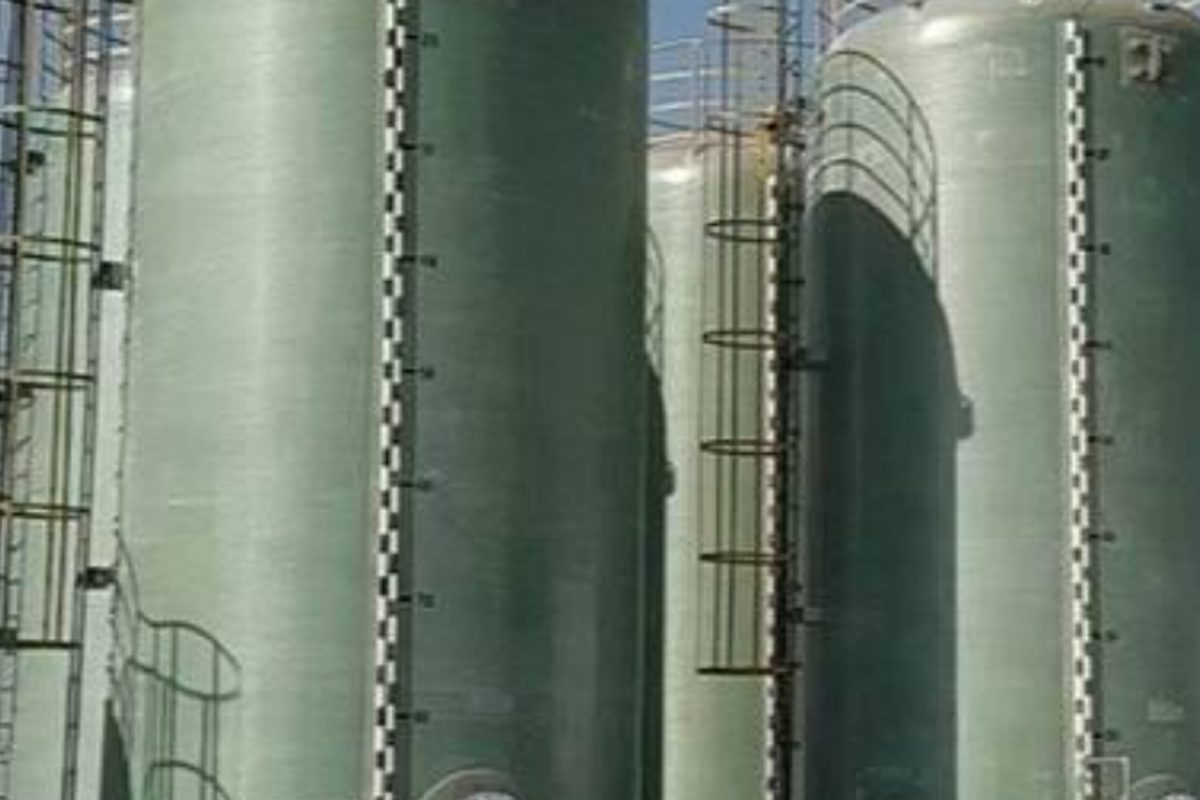
Ask a tank engineer where FRP chemical tanks fail and the answer is nearly always the same: at the barrier. The structural laminate - glass-rich, thick, strong - is not the corrosion-limiting layer. The 1-3 mm of resin-rich surface between the chemical and the structure is. Gel coat quality, veil selection, liner build and cure discipline decide whether a tank serves twenty-five years or blisters within two winters, and none of it is visible after the structural layers go on. Which is precisely why it must be specified, witnessed and tested while it is being made.
1. Anatomy of the Corrosion Barrier
A proper barrier is a laminate in its own right, built inward-out as:
| Layer | Function | Typical Build |
|---|---|---|
| Gel coat (where used) | Sealing skin, appearance, UV for exterior | 0.4-0.6 mm, chemical-grade or isophthalic |
| Veil layer (C-glass or synthetic) | Resin-rich surface, hides glass, smooths flow | 1-2 veils, ~0.3-0.5 mm wet |
| Chopped-strand liner | Resin-rich, low-void barrier body | 1.5-2.5 mm for chemical service |
| Structural laminate | Mechanical strength (wound / woven roving) | Per design - carries load, not corrosion duty |
| Exterior topcoat | UV and weather seal | 0.3-0.5 mm, no glass at surface |
The barrier principle: keep glass fibres away from the chemical. Glass-resin interfaces are wicking paths; a barrier with 2 mm of glass-free, low-void resin makes the shortest leak path long and tortuous.
2. Gel Coat vs Resin-Rich Liner: Choosing the Skin
Gel coats give a dense, glossy, easily-inspected surface and suit water, brine and many process fluids; their weakness is thickness control - sprayed too thin they pinhole, too thick they crack. Resin-rich liners built from veil plus chopped strand dispense with gel coat entirely and are the default for serious chemical service (acids, solvents, oxidizers) because their integrity is laminated, not sprayed. For dual-side service (inside and out aggressive), both faces get barrier construction - the outside of a tank over a hot acid sump is as much a corrosion surface as the inside.
3. Liner Thickness by Service
| Service | Barrier Build | Liner Resin |
|---|---|---|
| Potable / rainwater | Gel coat + 1 veil | Approved isophthalic or vinyl ester |
| Mild chemicals, brine | Veil + 1.5-2.0 mm liner | Isophthalic minimum |
| Acids (HCl, H2SO4 dilute), alkalis | 2 veils + 2.0-2.5 mm liner | Vinyl ester |
| Oxidizers, solvents, FGD liquor | 2-3 veils + 2.5-3.0 mm liner | High-grade vinyl ester / novolac |
| Vacuum service | Barrier per above, plus low-void verification | Blister resistance critical |
Thickness is verified during build - wet-film gauges at intervals on every course - because after the structural layers wind over, nobody can measure it again without grinding.
4. Cure: Where Barriers Are Won or Lost
An uncured or under-cured liner leaks monomer into the product, softens in service, and blisters when osmosis drives water through residual solubles. Cure discipline: correct catalyst ratio (measured, not eyeballed), ambient and substrate temperatures within the resin window, scheduled post-cure for shop-built tanks, and verification before shipment - Barcol hardness against the resin datasheet plus, for critical service, a solvent wipe or DSC sample check. Site-made joints and repairs repeat the same cure control; a perfect factory liner with a sloppy site repair is a tank with a designed-in weak point.
5. The Defect Catalogue: What Went Wrong Upstream
| Field Symptom | Upstream Cause | Prevention |
|---|---|---|
| Blistering within 1-3 years | Under-cure, trapped moisture/solvents, contaminated veil | Cure verification, dry storage, clean layup |
| Wicking stains along faint lines | Glass at or through the barrier (thin liner, bare mat) | Wet-film checks; veil count enforced |
| Crazing around nozzles | Gel coat too thick or flexed by pipe loads | Thickness control; nozzle load limits |
| Pinhole weeps in new tank | Gel coat sprayed too thin; poor wet-out | Wet-film gauge; spark test before structural layers |
| Barrier loss at drain/sump | Standing chemistry + abraded thin liner | Thicker liner at sumps; smooth drainage geometry |
Every one of these is cheap to prevent and expensive to explain to a plant manager - the economics of hold points are never clearer than here.
6. Hold Points for the Buyer
Specify barrier hold points that happen while they still can: liner resin brand and batch recorded; veil count and wet-film thickness logged per course; spark (holiday) testing of the liner at the specified voltage before structural build-up; Barcol values before shipment; and witness samples retained from production. For filament-wound tanks, confirm the liner is wound over immediately after its layers gel - a liner that skin-cures dusty before overwinding bonds poorly and becomes a delamination plane.
7. In-Service Inspection of the Barrier
Inspection is mostly visual plus touch: gloss loss and chalking track UV and chemical attack; blister maps recorded annually show whether a population is stable or growing; wicking stains mark where glass has reached the surface; and drainage low-points get extra attention because standing chemistry works the barrier hardest. Repairs follow the laminate discipline: grind back to sound, glossy laminate, rebuild veil-first with matching resin, cure and hardness-verify before refill. A barrier rebuilt in the right order is invisible in service; one rebuilt backwards is a repair scheduled to repeat.
Related reading: vinyl ester vs polyester resin selection, FRP chemical tank safety, and our filament-wound chemical storage tanks.
Need help selecting FRP products?
Our engineers answer technical questions free of charge.
Ask an Engineer on WhatsApp