
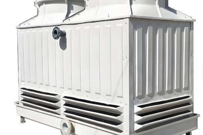
Cooling tower selection conversations usually start with a capacity in m³/h and end with a datasheet. In between sits a decision that shapes the tower's footprint, its fan power and how well it performs on the hottest, most humid day of the year: whether the air crosses the falling water or rises against it. Both configurations are built in FRP, both are sold as "industrial cooling towers", and both can meet the same duty - but they do it with different geometry, and that geometry changes what you buy and how you operate it.
This guide works through the thermal physics first, then the commercial consequences. If you are still at the sizing stage rather than choosing a configuration, our FRP cooling tower selection guide covers the sizing inputs; the maintenance side, including fill replacement intervals, is covered in our cooling tower fill maintenance guide.
1. What the Two Names Actually Describe
The names refer to the relative direction of air and water.
- Cross-flow: water falls vertically through the fill while air moves horizontally across it, entering through louvres along the full height of one or two faces. The water and air paths meet at roughly 90 degrees.
- Counter-flow: air enters at the base of the tower, travels upward through the fill against the descending water, and leaves through a fan at the top. The paths are close to 180 degrees apart.
Counter-flow is the configuration of most factory-assembled FRP towers, round or square, because the air path is short and the fan sits directly above the fill. Cross-flow dominates very large field-erected towers, and also appears in square FRP towers where the fill is arranged in two banks either side of a central air plenum.
Direction of flow is not a marketing preference. It determines the mean driving force available for evaporation, the static pressure the fan must overcome, and the space the tower occupies.
2. Range, Approach and Wet-Bulb: The Numbers That Size Any Tower
Three numbers define every cooling duty, and they are worth restating because a large share of tower disputes come from confusing them.
| Term | Definition | Typical design value |
|---|---|---|
| Range | Hot water temperature minus cold water temperature | 5 °C (common), 8-11 °C (large process towers) |
| Approach | Cold water temperature minus ambient wet-bulb temperature | 3-5 °C counter-flow; 4-7 °C cross-flow |
| Design wet-bulb | Ambient wet-bulb the tower is guaranteed against | 26-28 °C across most of Asia, Africa and the Middle East |
Approach is the hard limit. A tower can never cool water below the ambient wet-bulb, and in practice not below wet-bulb plus 2-3 °C even with unlimited fill. Approach is therefore the number that costs money: halving it requires roughly doubling the fill volume and the tower volume.
The heat rejection load follows directly from the range:
Q = m × cp × Range, where m is circulating water mass flow and cp is 4.186 kJ/(kg·K).
For 500 m³/h with a 5 °C range, Q = 500,000 × 4.186 × 5 / 3600 ≈ 2,907 kW. Every downstream decision - fan size, fill area, pump head - starts from that figure.
3. Fill Geometry and Air Path: Where the Performance Difference Comes From
Fill is where the mass transfer happens, and the two configurations use different fill.
- Counter-flow normally uses film fill: closely spaced PVC or PP sheets with fluted surfaces that spread water into a thin film. Because air and water are in contact over the whole fill height, the mean enthalpy difference between saturated air and the water stays large, which is why counter-flow reaches a tighter approach with less fill volume. Film fill is also prone to fouling, so water quality matters.
- Cross-flow historically uses splash fill - a grid of slats that breaks water into droplets - and more recently film fill arranged in tall banks. Air enters across the full fill height, so pressure drop per metre of fill is lower, but the air leaving the top of the bank has already been humidified by the water at the bottom of it, which reduces the mean driving force.
The practical consequence: for the same approach, cross-flow needs more fill volume and more plan area, but asks less of the fan.
4. Thermal Performance Compared
| Parameter | Counter-flow | Cross-flow |
|---|---|---|
| Minimum practical approach | 2.8-4 °C | 4-5.6 °C |
| Fill height for a given duty | 1.2-1.8 m (single pass) | 3.0-5.0 m of bank height |
| Water loading on fill | 15-30 m³/h per m² (film fill) | 10-20 m³/h per m² (splash fill) |
| Air-side pressure drop | Higher: fill plus eliminator plus plenum | Lower: short horizontal path |
| Sensitivity to fill fouling | High | Moderate |
| Performance at high wet-bulb | Better, larger mean driving force | Falls away more quickly |
That last row is the one that decides projects in tropical and subtropical locations. A tower sized on a 26 °C wet-bulb with 2 °C of margin will not hold its cold water temperature on a 29 °C day, whichever configuration you pick - but the counter-flow tower will lose less capacity, because its mean enthalpy difference is larger to begin with.
5. Fan Power, Drift and Water Loss
Fan power is the operating cost line that separates the two designs most clearly.
| Item | Counter-flow | Cross-flow |
|---|---|---|
| Typical fan static pressure | 120-200 Pa | 70-120 Pa |
| Fan power as share of heat rejection | 0.8-1.5 % | 0.5-1.0 % |
| Drift loss with modern eliminators | 0.005-0.02 % of circulating flow | 0.01-0.03 % of circulating flow |
| Evaporation loss | about 0.15 % of circulating flow per °C of range | same, within measurement tolerance |
| Blowdown | set by cycles of concentration the make-up water allows | same |
For a 500 m³/h tower with a 5 °C range, evaporation alone is about 7.5 m³/h. Drift at 0.01 % is 0.05 m³/h - small in volume, but it is the fraction that carries dissolved solids onto nearby surfaces, so drift eliminators and their condition deserve attention in any specification.
Fan energy is not trivial at scale: 1 % of 2,907 kW is roughly 29 kW, which over 6,000 operating hours is around 175,000 kWh per year. A cross-flow tower may save a meaningful share of that, at the cost of a larger footprint and a slightly worse approach.
6. Footprint, Layout and Multi-Cell Arrangements
Cross-flow towers are wide and low; counter-flow towers are compact and tall.
- A counter-flow tower can be installed with its air inlet facing almost any direction and needs only a clear approach around the base - typically half the inlet height, and never less than 1 m.
- A cross-flow tower needs clear space along the louvred faces, otherwise recirculation of humid exhaust air raises the entering wet-bulb and destroys the guaranteed approach.
- Above roughly 1,000 m³/h, multi-cell arrangement is standard. Cells should be identical so that water distribution stays balanced; unequal cells, or a common basin with a badly placed partition, are a common cause of one cell running dry.
On rooftops the deciding factor is usually structural: a cross-flow tower spreads its weight over a larger area, while a counter-flow tower concentrates it and adds fan-stack wind load. Our FRP vs stainless steel comparison covers the weight and corrosion trade-offs of the shell itself.
7. Cold Weather, Plume and Freeze Protection
Both configurations form a visible plume in cool, humid weather, because the exhaust air is saturated. Two differences matter in winter:
- Counter-flow is more prone to ice on the inlet louvres and on the fan stack lip, and to ice build-up in the fill if water loading is reduced well below design.
- Cross-flow tends to ice in the fill of the windward face, where cold air enters at the top of the bank and meets the warmest water.
Standard protections, applicable to either type: a remote or indoor sump so the basin never freezes, basin heaters sized at roughly 10-30 W per m² of basin area, fan reversal or two-speed motors for de-icing, and a control scheme that never reduces water flow below about 50 % of design. FRP shells tolerate freeze-thaw cycling far better than concrete, and better than carbon steel with damaged coating - one reason FRP is specified for winter-exposed installations.
8. Worked Selection Example: 500 m³/h from 37 °C to 32 °C
Take a plant in Southeast Asia with a design wet-bulb of 28 °C.
- Range = 37 - 32 = 5 °C. Approach = 32 - 28 = 4 °C.
- Heat rejection Q = 500,000 × 4.186 × 5 / 3600 ≈ 2,907 kW.
- A 4 °C approach sits at the edge of cross-flow capability and comfortably inside counter-flow capability. Choose counter-flow.
- Size the fill area from water loading: at 20 m³/h per m², plan fill area = 500 / 20 = 25 m². Add 10-15 % for distribution losses and margin: about 28 m².
- With a 1.5 m fill height, the tower needs roughly 28 m² of plan area - a 5.3 m square, or two cells of about 2.7 m by 5.3 m. Select the nearest standard square FRP tower size above that figure.
- Fan: at 120-200 Pa static and the design air flow, expect 0.8-1.5 % of Q, that is 23-44 kW. Specify a low-noise unit at 36 dB(A) or better at 15 m if the site is near a boundary.
- Water loss: evaporation 7.5 m³/h, drift about 0.05 m³/h, blowdown set by make-up water chemistry. Size the make-up line and basin overflow accordingly.
Note the direction of the argument: the approach chose the configuration, and the configuration then fixed the footprint and the fan power. Choosing the configuration first and then demanding an approach it cannot deliver is the single most common selection error.
9. FRP Construction Details That Decide Service Life
The shell is not the whole story, but it is the part that fails first when it is under-built.
- Resin and gelcoat: isophthalic or vinyl ester resin with a UV-stabilised gelcoat on all external surfaces. A fire-retardant formulation tested to ASTM E84 is worth requesting for indoor or occupied-roof installations.
- Laminate thickness: panels thick enough to resist fan-stack vibration and wind load without drumming. Ask for the laminate schedule, not only the resin type.
- Fasteners: stainless steel 304 or 316 bolts with isolating washers, or bonded FRP joints. Mixed metals without isolation are a galvanic corrosion site.
- Fill and eliminators: UV-stabilised PVC or PP, with eliminator efficiency quoted in the same terms as the drift guarantee.
- Fan and drive: IP55 motor, and a gear or belt drive that can be serviced without lifting the fan stack.
HuanGang manufactures square and round FRP towers within the complete equipment range, including the square FRP industrial cooling tower for modular multi-cell layouts, round counter-flow towers for packaged duties, and anti-clogging round towers where the circulating water carries suspended solids. Fan decks and structural panels are available separately as FRP fan deck panels for cross-flow assemblies.
10. Specification Checklist and Common Mistakes
| Specify this | Why it matters |
|---|---|
| Duty: flow, hot and cold water temperature, design wet-bulb, site altitude | Altitude reduces air density and therefore mass flow; a tower sized at sea level loses capacity at 1,500 m |
| Configuration and cell arrangement | Fixes footprint, fan power and freeze behaviour |
| Approach and guaranteed performance standard | Ask for CTI STD-201 style thermal performance certification or a factory test report |
| Drift guarantee in % of circulating flow | Drift, not evaporation, is what deposits solids on nearby equipment |
| Sound pressure level at a stated distance | "Low noise" without a distance and a dB(A) figure is not a specification |
| Fill type, height and material | Determines fouling tolerance and replacement interval |
| Laminate schedule, resin type and fire class | Determines service life and code compliance |
| Freeze protection scope for cold climates | Basin heaters, remote sump, fan reversal |
Five mistakes recur often enough to list:
- Specifying an approach the chosen configuration cannot reach, then blaming the tower for the shortfall.
- Sizing on average wet-bulb instead of design wet-bulb, leaving no capacity on the worst day of the year.
- Ignoring recirculation - a cross-flow tower pushed against a wall ingests its own exhaust.
- Reducing water flow at part load without resetting the fan, which starves the upper fill and causes scaling.
- Buying on shell price alone. Fill, eliminators, fan drive and fasteners are the parts that need replacing, and they are the parts cheapest to downgrade.
Send your duty point, design wet-bulb and site constraints to our engineers and we will confirm the configuration, cell arrangement and guaranteed approach before you commit to a footprint. For the wider material comparison behind the shell, see FRP manufacturing processes explained.
Need help selecting FRP products?
Our engineers answer technical questions free of charge.
Ask an Engineer on WhatsApp