
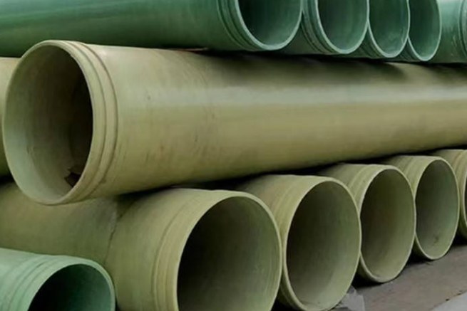
Two GRP pipes can leave the same factory with the same diameter, the same resin system and the same glass content and still behave completely differently in service. The difference is the angle at which the roving was laid down. A filament winding machine can place fibres at ±55° to the pipe axis, at ±80°, or as a deliberate mix of the two, and each of those laminates answers internal pressure, support bending and restrained thermal movement in a different way.
This matters commercially because the winding angle is invisible on a purchase order. A datasheet reading "filament wound GRP pipe, PN16, vinyl ester" is not a material specification: it does not say whether the axial tensile modulus is 9,000 MPa or 15,000 MPa, whether a six-metre support span is acceptable, or how much axial movement a restrained run will develop. All three answers follow from the fibre architecture, and none of them can be recovered later by adding resin.
This guide works through the engineering: the stress ratio that drives the angle, the netting analysis behind the familiar 55°, how to read a filament-wound call-out against ASTM D2996, a worked wall-thickness example with and without temperature derating, the corrosion barrier the angle cannot protect, support spacing, joints, nozzles, and the incoming checks that catch a bad laminate before it is buried.
1. What the Winding Angle Actually Controls
The angle between the roving and the pipe axis decides how much fibre crosses any given cut through the wall. Imagine a longitudinal slit along the pipe: a hoop layer laid at 88° is crossed almost perpendicularly by the fibres and contributes its full strength against that cut. Imagine a circumferential cut around the pipe: a hoop layer contributes almost nothing, and only the axial component of the helical plies resists it. Changing the winding angle moves fibre from one of those two directions to the other, and nothing else in the process does the same job as directly.
The consequence is a strongly orthotropic wall. For a typical filament-wound GRP pipe wound at about 55°, hoop tensile modulus falls in the region of 18,000-28,000 MPa while the axial tensile modulus sits at roughly 9,000-15,000 MPa: the wall is close to twice as stiff circumferentially as it is axially. Wind the same wall predominantly at 85-89° and the hoop direction gains both stiffness and strength, at the cost of axial fibre - a hoop-dominant pipe resists pressure well and bending badly.
Three limit states therefore have to be traded off against each other:
- Hoop burst from internal pressure. This is the load case most specifications are written around, and it is what a hoop or near-hoop layer buys.
- Axial and bending stress from support spans, water hammer and thrust, differential settlement, and restrained thermal contraction. A wall that has no low-angle fibre has nothing carrying this beyond the resin and the helical component.
- External load and buckling in buried service, where wall stiffness rather than strength usually sets the thickness.
It is equally important to be clear about what the winding angle cannot fix. It cannot improve chemical resistance, which is the job of the resin system and the corrosion barrier. It cannot buy impact tolerance, which comes from thickness and construction. It cannot change the temperature ceiling, which is set by the resin's heat deflection temperature. Those three are the subject of separate decisions; the angle is a structural decision.
| Layer / pattern | Typical angle to axis | Primary duty | Where it appears |
|---|---|---|---|
| Hoop (circumferential) winding | 85-89° | Carries hoop stress from internal pressure and resists buckling | Structural wall of pressure pipe and tank shells |
| Helical (balanced) winding | ±45-60°, nominal ±55° | Shares hoop load and provides axial strength plus bending stiffness | The default structure of a wound pressure pipe or tank shell |
| Low-angle layer | ±10-25° | Axial strength, thrust and restrained thermal loads | Long unsupported runs, anchored or restrained lines |
| ±45° pair | 45° | Shear and torsion | Shafts, torque tubes, some spools and risers |
| Chopped strand mat / hand lay-up overlay | Random | Quasi-isotropic build-up where the pattern is interrupted | Butt-and-strap joints, fittings, pads and repairs |
A filament-wound wall is not an isotropic material with a different density. It is a fibre architecture with two very different sets of properties in two directions, and the winding angle is the dial that sets the ratio between them.
2. Netting Analysis: Why 54.7° Keeps Reappearing
The classic starting point is netting analysis, which assumes that the fibres carry all the load and the resin only transfers it between them. For a thin-walled closed cylinder, the two principal stresses are not equal: hoop stress is σh = pr/t and axial stress is σa = pr/2t, a 2:1 ratio. Take a balanced ±α layup, write the free-body equilibrium in both directions, and the fibre tension balances the two stresses only when:
tan²α = 2, so α = 54.7°
That is the "magic angle". At a winding angle of about 55° from the axis, the fibres are inclined just enough toward the circumferential direction to carry twice as much stress in the hoop direction as in the axial direction - exactly what a closed-end vessel needs. It is the same angle that braided fire hoses use, for the same reason. ISO 14692, the petroleum and gas industry GRP piping standard, refers directly to the "typical 55° winding angle of filament wound pipe", and expresses its long-term test envelope at a 2:1 hoop-to-axial biaxial ratio because that is the condition a 55° laminate is built for.
Three practical qualifications keep this from being a recipe:
- Closed ends are the premise. The 2:1 ratio exists because the pressure pushes against end closures and generates axial stress. A pipe run in a purely gasketed, unrestrained system has almost no axial stress from pressure, so hoop loading dominates and a hoop-heavy (±75-85°) wall is efficient. Thermal and bending loads do not disappear, however, and they are the reason hoop-heavy pipe still carries a light helical layer.
- Real laminates are hybrids. A commercial chemical-service pipe typically starts with the corrosion barrier (veil plus chopped strand mat), then helical ±55° structural plies, then hoop plies at 85-89° that are commonly 15-30% of the structural thickness, and sometimes low-angle plies where axial stiffness is needed.
- Netting analysis ignores the resin. It gives the right answer for the fibre direction and the right instinct about the angle, but not the actual wall thickness. Thickness in a wound pipe is set from the long-term hydrostatic design basis of the laminate, per ASTM D2992, and the letters in the call-out that follow from it.
| Loading condition | Hoop : axial stress | What the laminate must do | Sensible winding pattern |
|---|---|---|---|
| Closed-end pressure (tank shell, pipe with blind flanges or restrained ends) | 2 : 1 | Balance both directions | ±55° helical, or ±55° with 15-30% hoop plies |
| Open-end pressure (pipe in a flexible-joint system) | 1 : 0 | Carry hoop only, plus handling rigidity | ±75-85° hoop-heavy with a light helical layer |
| Bending between supports, long unsupported spans | Axial bending | Axial fibre and bending stiffness | Add low-angle plies; increase wall before raising fibre content |
| Restrained thermal movement, anchored or buried with restrained joints | Axial compression or tension | Axial capacity and buckling resistance | Low-angle plies; anchorage and guide design, not angle alone |
| Torsion (shafts, spools subject to twist) | Shear | Shear strength and stiffness | ±45° pair |
3. Reading a Filament-Wound Pipe Call-Out: What ASTM D2996 Fixes
ASTM D2996 is the product specification for machine-made filament-wound "fibreglass" (glass-fibre-reinforced thermosetting resin) pipe, historically referred to as RTRP. It classifies pipe by process type, resin grade, liner type and a long-term pressure category, and it ties the classification to a set of test methods rather than to a sales description. For a buyer, four clauses do most of the work:
- The pressure category letter comes from a regression, not from a burst test. ASTM D2992 contains two procedures: Procedure A, a cyclic test extrapolated to 150 million pressure cycles, and Procedure B, a static test extrapolated to 100,000 hours of continuously applied pressure - about 11.4 years. Both produce a hydrostatic (or pressure) design basis, which is then multiplied by a service design factor to give the design stress. Category letters for the static route run from Q at 5,000 psi (34.5 MPa) up to Z at 31,500 psi (217 MPa), and for the cyclic route from A at 2,500 psi (17.2 MPa) to H at 12,500 psi (86.2 MPa).
- The thickness in a stress calculation is the structural thickness. The pressure rating follows S = P(D - t) / 2t, where D is the mean outside diameter, t the minimum reinforced wall thickness and S the allowable hoop stress. Rearranged: t = P·D / (2S + P). The corrosion barrier is excluded, and using the nominal total wall instead of the structural wall is one of the most common causes of under-designed pipe.
- Wall thickness has a floor per pipe. The minimum wall thickness at any point shall be no less than 87.5% of the nominal wall thickness published in the manufacturer's literature. That 12.5% tolerance is what an inspector measures against.
- The angle shows up in the mechanical cells. D2996 cells require a longitudinal tensile strength in the 8,000-55,000 psi (55-379 MPa) range, a longitudinal tensile modulus of 1-6 × 10⁶ psi (6,900-41,400 MPa) and pipe stiffness of 5-144 psi (34-993 kPa) measured at 5% deflection per ASTM D2412. A hoop-dominant wall with little axial fibre has difficulty reaching the upper longitudinal cells, which is exactly the constraint the winding schedule has to answer.
Supporting test methods in the same family, all worth naming in a purchase order: ASTM D3567 for dimensions and tolerances, D1599 for short-term burst (hoop tensile), D2105 for longitudinal tensile properties, D2412 for pipe stiffness, D2925 for beam strength, D4161 for restrained gasketed joints, D4024 for machine-made flanges, D5421 for contact-moulded flanges and D5685 for pressure pipe fittings. Socketing them together is what separates a specification from a catalogue entry.
| ASTM D2996 long-term category | Cyclic route (Procedure A), hoop stress | Static route (Procedure B), hoop stress |
|---|---|---|
| Lowest categories | A: 2,500 psi (17.2 MPa) | Q: 5,000 psi (34.5 MPa) |
| Upper-middle categories | E: 6,300 psi (43.4 MPa) | T: 10,000 psi (68.9 MPa) |
| Highest categories | H: 12,500 psi (86.2 MPa) | Z: 31,500 psi (217 MPa) |
One warning belongs directly under that table. A category letter is a long-term strength at the standard's reference condition, and it is not a temperature-derated pressure rating. Derating for service temperature and chemical environment comes from the design code - ISO 14692 for piping in the petroleum and gas industries, or the manufacturer's qualified envelope - not from ASTM D2996. If a supplier quotes "ASTM D2996, Category T" as though it were a working pressure at 70 °C, the derating step has been skipped.
4. Worked Example: A DN300 PN16 Line at 23 °C and at 65 °C
Take a DN300 line, 315 mm outside diameter, rated PN16 (1.6 MPa), carrying 20% hydrochloric acid at 65 °C, in vinyl ester. Assume the pipe is qualified under ASTM D2992 Procedure B at a static hydrostatic design basis of 68.9 MPa (Category T) at the standard reference condition, and that the owner applies a service design factor of 0.5, giving an allowable hoop stress of 34.5 MPa. Wall thickness then follows t = P·D / (2S + P):
| Design case | Partial factors applied | Allowable hoop stress S | Required thickness t | Specify |
|---|---|---|---|---|
| 23 °C, static pressure only | None (reference condition) | 34.5 MPa | 7.1 mm | 7.5 mm nominal |
| 23 °C, cyclic pressure (frequent start/stop) | Cyclic service factor 0.90 | 31.1 MPa | 7.9 mm | 8.0 mm nominal |
| 65 °C, static pressure | Temperature factor 0.80 | 27.6 MPa | 8.9 mm | 9.0 mm nominal |
| 65 °C, cyclic pressure | Temperature 0.80 × cyclic 0.90 | 24.8 MPa | 9.8 mm | 10.0 mm nominal |
The factors of 0.80 and 0.90 are illustrative: in a real design they are read from the partial-factor tables of ISO 14692-3 or from the manufacturer's qualified envelope for that specific laminate, medium and temperature. What the table is meant to show is the arithmetic of derating - a 1.6 MPa line at 65 °C needs roughly 40% more wall than the same line at reference temperature, and it is not the pressure that drives it.
Two further checks close the design. First, the actual hoop stress in the 9.0 mm wall is σh = P(D - t) / 2t = 1.6 × 306 / (2 × 9) = 27.2 MPa, with an axial stress at the 2:1 ratio of about 13.6 MPa - for which the axial fibre content has to be there. Second, the strain at that stress, taking a hoop modulus of 20,000 MPa, is 0.14%. Many operators apply a 0.2% strain limit to protect against strain corrosion in chemical service, which means 9 mm passes with a margin while the 7.5 mm wall (0.16%) is closer to the limit than its stress margin suggests. Strength and strain are two different governors, and the thinner of the two answers is not always the one that governs.
5. The Corrosion Barrier: The Layer the Winding Angle Cannot Fix
The structural plies can be perfectly wound and the pipe still fails within a few years if the barrier is wrong. In chemical service the inner surface is built deliberately resin-rich: a surfacing veil, giving a resin-saturated layer of roughly 0.25-0.4 mm, followed by one or two chopped strand mat plies, for a total of about 2.5 mm (100 mil), which is the minimum most codes and client specifications call for.
The composition matters more than the thickness for chemical resistance. A veil layer is around 90% resin by volume; chopped strand mat layers are 25-30% reinforcement by weight; overall the barrier is 70-85% resin by volume and contributes essentially no structural strength. It is bonded to the structural laminate and excluded from the stress calculation, which is why a "10 mm wall" and a "10 mm structural wall" are not the same pipe.
| Barrier build-up | Typical thickness | Service it suits |
|---|---|---|
| Veil + 1 chopped strand mat | 2.5 mm | Water, neutral salts, dilute acids at moderate temperature |
| Veil + 2 chopped strand mat | 3.5-4.0 mm | Hot dilute acids, hypochlorite, flue gas ducting, tanks in continuous chemical service |
| Synthetic veil + 2 chopped strand mat | 4.0-5.0 mm | Hydrofluoric acid, strong hot alkali, aggressively oxidizing media |
Two design rules keep the barrier honest. First, ASME RTP-1 places the corrosion barrier under a tensile strain limit rather than a strength limit: 0.13% under sustained load, falling to 0.10% for resins with an elongation below 4%, and 0.20% under intermittent load. That limit constrains the structural laminate design from the inside out. Second, the veil material has to match the chemistry - glass is attacked by hydrofluoric acid, so HF service demands a synthetic veil even when the resin itself is rated for the medium.
The structural laminate carries the pressure. The corrosion barrier is what decides whether there is still a structural laminate to carry it in ten years.
For the resin side of that decision - which family to use, at what temperature, and how to prove it with immersion coupons - the companion article is FRP resin selection for chemical equipment.
6. Stiffness, Support Spacing and the Axial Modulus Trap
Because the winding angle sets the axial modulus, it also sets the support spacing, and this is where a hoop-heavy wall quietly costs money. GRP design normally controls deflection, not stress: a typical limit is 12.5 mm, or 0.5% of the span, whichever is smaller. For spans longer than 2.5 m the fixed 12.5 mm limit governs. The maximum span for a uniformly loaded span follows the standard beam equation rearranged for length:
L = ( 384 · E · I · δ / (5 · w) )1/4
Take a DN300 pipe with a 9 mm wall (second moment of area I ≈ 1.01 × 108 mm4) filled with water (w ≈ 0.70 N/mm) and a deflection limit of 12.5 mm:
| Axial modulus Ea | Winding pattern it belongs to | Maximum span for δ = 12.5 mm | Change versus the stiffest case |
|---|---|---|---|
| 15,000 MPa | Helical-dominated with low-angle axial plies | 6.8 m | Reference |
| 12,000 MPa | Balanced ±55° helical structure | 6.4 m | -6% |
| 9,000 MPa | Hoop-dominant with minimal axial fibre | 6.0 m | -12% |
The good news is in the exponent: because span scales with the fourth root of stiffness, losing 40% of the axial modulus costs only about 12% of the span. The bad news is elsewhere. Thermal movement scales directly with the coefficient of thermal expansion, and the coefficient is set by the same fibres: a ±55° laminate sits in the region of 1.5-2.5 × 10⁻⁵/K axially, while a hoop-dominant wall can reach 3-4 × 10⁻⁵/K - as much as three times that of carbon steel - because the axial direction is then mostly resin. A hoop-heavy pipe that was chosen to save 15% of wall thickness can double the expansion loop and guide requirements on a long hot run.
Axial design also has to survive restraint. Where both ends of a hot line are anchored, restrained expansion becomes axial compression in the wall, and a wall with little axial fibre has both a lower compressive capacity and a lower buckling resistance. The fix is usually a proper loop and guide arrangement rather than more hoop fibre, but it has to be designed before the winding schedule is frozen, not after the first anchor block is poured.
7. Fittings, Joints and the Angle Discontinuity
A wound pipe is a continuous, well-controlled laminate. A joint is not, and in chemical service the joint is usually what governs. ISO 14692-3 makes the point explicitly: the reinforcement angle in some fittings and joints can vary greatly from the typical 55° winding angle of filament-wound pipe, so a joint with equal amounts of reinforcement in the axial and hoop directions has a long-term envelope closer to a square than to the trapezoidal envelope of the pipe. The standard's premise is that fittings and joints are at least as strong as the plain pipe under any loading condition - and where they are not, additional reinforcement or wall thickness is required to get there.
In practice this is what to watch for:
- Butt-and-strap joints are built by hand lay-up, typically chopped strand mat with woven roving, and the strap ends up quasi-isotropic - good axial strength, limited hoop strength. They need the specified number of layers, a proper taper onto the pipe surface, correctly mixed and rolled-out resin, and a controlled cure. A joint that was easier to lay because it was resin-rich is a joint that will crack at the toe.
- Gasketed joints. Restrained gasketed joints are qualified under ASTM D4161. Rubber-ring joints are the normal choice for low-pressure water and sewer; laminated joints are preferred at DN1000 and above, or where the pressure class rises; flanged joints are used where the line has to be opened regularly.
- Flanges. Machine-made flanges are covered by ASTM D4024 and contact-moulded flanges by D5421. When an FRP flange is bolted to a metal flange, use a full-face gasket (commonly 3 mm, 50-60 Shore A) and flat washers under every nut; a metal raised face bearing directly on the FRP flange face transfers a bending moment into the laminate and is a classic source of flange cracking. As the pressure class rises, many fabricators prefer a stub end with a metallic backing ring, so that the bolting load is carried by the ring rather than by the laminate.
- Fittings should match the pipe. An elbow or tee made with a different resin/glass combination, or with a different wall build-up, invalidates the qualification of the line. Order pipe and fittings from one qualified source, or require the fitting's qualification data as a separate submittal.
8. Nozzles, Openings and Branches in a Wound Shell
Every opening in a wound shell cuts hoop fibres. Whatever is left around the opening - the angle of the plies still crossing it - has to carry the hoop stress that the removed fibres were carrying, which is why an opening is reinforced for hoop continuity and not merely stiffened with a pad.
What a good design submittal shows:
- Replacement of the cut fibre, calculated in the fabricator's design report under the code the vessel is built to - the opening reinforcement rules of ASME RTP-1, or the branch requirements of ISO 14692 for piping. The reinforcement is added plies, bonded and tapered into the shell, with the pad extending beyond the opening to develop the load.
- No stopping short. Reinforcement plies must cover the full area required, taper out at the specified rate, and be laid without entrapped air. A pad that ends abruptly creates a hard edge that becomes a crack initiator.
- Attention to small nozzles. A small unreinforced hole in a thin shell carries a stress concentration of the order of two to three times the nominal hoop stress, so even a DN25 instrument nozzle on a wound shell should be shown as reinforced.
- Manways placed where they can be inspected. On tanks the manway is the largest opening and the one opened most often; it should be positioned where the shell strain is lowest and where an inspector can work, with a bolted cover and a full-face gasket.
- Sealed cut edges. Every cut edge of an opening exposes fibre that will wick liquid into the laminate if it is left bare. Resin-sealing the cut, and covering it with the reinforcement plies, is a two-minute detail that decides whether the opening stays tight.
9. Incoming Checks That Catch a Wound-Laminate Problem
Most of what goes wrong with wound laminates is detectable before the pipe goes into the trench. A practical receiving inspection covers six items:
| Check | Method / reference | Acceptance |
|---|---|---|
| Wall thickness, several points per length | Ultrasonic or mechanical, per ASTM D3567 | Never below 87.5% of nominal at any point (ASTM D2996) |
| Barcol hardness | ASTM D2583 | At least 90% of the resin manufacturer's fully cured value; a soft wall means incomplete cure |
| Glass content | Ignition loss per ASTM D2584 | Typically 60-75% by weight in a wound structural laminate; low values indicate resin-rich, under-strength wall |
| Visual condition | Defect classification per ASTM D2563 | No delamination, dry fibre, resin-starved areas or pinholes in the corrosion barrier |
| Fibre angle | Measure the roving angle against the axis on an end trim or a scrapped ring | Matches the ordered schedule; the only check that verifies the laminate you specified |
| Pressure test | Field hydrotest per the project code; ISO 14692-3 applies a hydrotest factor f2 = 0.89 with the chemical and cyclic partial factors set to 1.0 | Hold pressure without leakage, weeping or visible movement; record time and temperature |
Test specimens in the ASTM D2996 family are conditioned at 23 ± 2 °C and 50 ± 10% relative humidity for at least 48 hours before testing, which is worth remembering when a supplier's certificate is dated the same day as the shipment. And note the one check that cannot be done on site: whether the laminate actually qualified under D2992 at the right category. That is a document, so ask for the regression report, not a summary line on a datasheet.
10. Specification Checklist and Common Mistakes
| Specify this | Why it matters |
|---|---|
| Governing product standard and design code | ASTM D2996 for the pipe, ISO 14692 or the project code for the system; the two answer different questions |
| Structural wall thickness, separately from total wall | The corrosion barrier does not carry stress; nominal wall in a stress calculation underpredicts by up to 30% |
| Long-term design basis and the procedure used | Static (D2992 Procedure B, 100,000 h) or cyclic (Procedure A, 150 million cycles), with the category letter |
| Winding schedule | Helical angle(s), hoop proportion and any low-angle plies, stated as a percentage of structural thickness |
| Axial tensile modulus and the deflection check | Sets support spacing; state whether creep and service temperature are included |
| Temperature and chemical partial factors | The difference between a 7.5 mm and a 10 mm wall on the same line |
| Corrosion barrier thickness and veil type | Chemical resistance, and the strain limit that constrains the structural design |
| Joint and fitting qualification | Joints usually govern; require at least pipe-equivalent strength, plus D4161 data for gasketed joints |
| Receiving inspection requirements | Thickness, Barcol, ignition loss, visual class and fibre angle |
| Certificates | D2992 regression report, batch traces for resin and glass, hydrotest record |
The mistakes that recur, roughly in order of frequency:
- Ordering "PN16 GRP pipe" with no winding schedule, then discovering the axial modulus is half of what the support spacing assumed.
- Using the nominal wall in the stress calculation, so the real structural wall is 2.5-4 mm thinner than the design intended.
- Designing on a static category letter for a line that cycles daily; the cyclic category is the lower of the two for a reason.
- Applying an ambient-temperature allowable stress to a 65-70 °C service without derating.
- Specifying hoop-dominant pipe for a long hot run, then paying for the expansion loops and guides that the resulting thermal movement demands.
- Forgetting the strain check on the corrosion barrier, which is stricter than the strength check in many chemical services.
- Buying pipe from one source and fittings from another, so the joint is unqualified against the pipe it is joining.
- Accepting a laminate on Barcol hardness alone, with no glass content and no fibre angle verification.
HuanGang manufactures filament-wound GRP process pipe and wound chemical-service equipment within our FRP pipes and fittings range: custom filament-wound GRP/FRP process pipes, FRP pressure pipe for higher-pressure lines, and corrosion-resistant FRP flange and pipe fittings to match them. On the equipment side, the FRP storage tank programme includes the filament-wound FRP chemical and HCl mixing tank. On the shop-floor side, the 4-axis filament winding machine line is what puts the angle into the laminate. Send us the line list - diameter, pressure, medium, temperature, support arrangement and whether the ends are restrained - and we will return a winding schedule and wall thickness with the derating worked through. For the wider context, see our GRP pipe specification guide and pipe diameter and wall thickness selection.
Need help selecting FRP products?
Our engineers answer technical questions free of charge.
Ask an Engineer on WhatsApp