
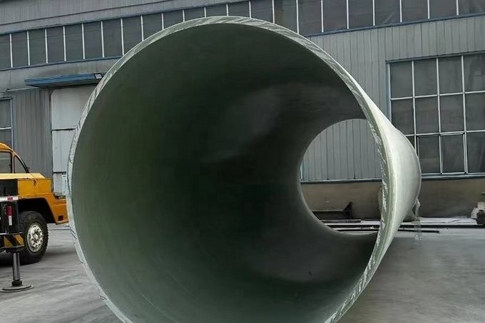
A buried GRP pipe is not a tube that happens to be underground. It is half of a composite structure, and the other half is the soil you backfill around it. Get the embedment right and a DN800 SN 5000 line will sit inside a 5 % ring deflection limit for fifty years with room to spare. Get it wrong and the same pipe will ovalise past 15 % in the same trench, whether you bought SN 2500 or SN 10000. This guide sets out how EN 1295-1 and ATV-DVWK-A 127 actually treat a flexible pipe, what the soil zones and bedding classes mean in practice, a worked DN800 deflection calculation across four soil qualities and three stiffness classes, how to specify compaction so the calculation is not fiction, and the acceptance checks that catch a bad trench before the asphalt goes back on.
1. What "Flexible Pipe" Really Means for GRP
Steel and concrete pipes are designed to carry the load themselves and hand it to the ground only at the invert. A GRP pipe does the opposite: it deflects slightly, mobilises passive soil pressure at its springlines, and from that point on the pipe and the surrounding soil share the load. The pipe's job is to deflect enough to engage the soil without deflecting so far that the laminate strains, the joints open or the bore collapses.
Three consequences follow, and every one of them is a specification decision rather than a manufacturing one:
- Pipe stiffness (the SN class) is only one term in the load path, and usually the smaller one.
- The modulus of the embedment, generally written E', is the dominant term — and it is created on site, not in the factory.
- Deflection, not stress, is normally the governing check for buried GRP. That is the opposite of the above-ground pressure design case, where hoop strain governs.
ATV-DVWK-A 127 makes the point formally with its stiffness ratio VRB = 8 · S0 / SBh, where S0 is the pipe's ring stiffness and SBh the bedding stiffness. Above one threshold the system behaves flexibly, below it rigidly. GRP, like most plastics, falls on the flexible side — which is why the worksheet then requires short-term (one minute) and long-term (fifty year) verification for it, while steel and concrete are checked once.
2. Two Design Languages You Will Meet in a Tender
European and Middle East GRP specifications usually land on one of two calculation traditions, and they ask for different site data. Knowing which one governs tells you which numbers the contractor must produce.
| Item | EN 1295-1 route | ATV-DVWK-A 127 route |
|---|---|---|
| Character of the method | Design charts and bedding factors; the pipe-soil system is simplified into a bedding factor applied to a load | Full static calculation of the pipe-soil system at three points on the ring |
| Soil input | Bedding type (granular bed, granular bed and haunch, granular surround, concrete surround) with an assumed modulus E | Soil group G1–G4 plus degree of compaction, used to derive moduli for four separate soil zones E1–E4 |
| Points verified | Crown and springline through the bedding factor | Crown, springline and invert, on both the inside and outside faces |
| Time dependence | Handled through the deflection lag factor and long-term modulus | Explicit two-point check: one minute and fifty years |
| Typical bedding factors / moduli | Concrete bed 2.6; granular bed and haunch 1.9; granular bed 1.5; granular or sandy bed 1.1; granular surround 2.2 | Bedding cases I, II and III with the load distribution adjusted to the actual bearing angle |
| Companion documents | BS 9295 for the design of buried flexible pipes; ISO/TR 10465-3 for deflection parameters | DWA-A 161 for trenchless installation; DWA-A 143-2 for rehabilitation |
The bedding factors in the left-hand column are the ones used in UK highway drainage practice and are a good sanity check on any contractor's trench detail. A granular bed with no haunching is worth a factor of 1.1; the same material taken up around the pipe haunches to a decent bearing angle is worth 1.9. Nothing else in the trench changes that much.
3. Soil Groups, Soil Zones and the Silo Effect
ATV-DVWK-A 127 divides ground into four groups and the trench into four zones. Both distinctions matter, because a trench is rarely one material.
| Soil group | Description | Stiffness hierarchy |
|---|---|---|
| G1 | Non-cohesive, well-graded sands and gravels | Best — highest modulus at a given compaction |
| G2 | Low-cohesion sandy silts and gravelly clays | Good when compacted and drained |
| G3 | Cohesive mixed soils and silts | Moderate, sensitive to moisture |
| G4 | Cohesive clays | Poorest — low modulus, high time dependence |
| Zone | What it is | Why it matters |
|---|---|---|
| E1 | Soil above the pipe, inside the trench | Drives the vertical load through the silo effect |
| E2 | Embedment to the side of, and below, the pipe within the trench | This is the term you control with compaction and it dominates the deflection result |
| E3 | In-situ soil laterally outside the trench wall | Carries the arching reaction; without it the trench walls yield and the sidefill cannot develop pressure |
| E4 | In-situ material below the pipe zone | Foundation stiffness; governs whether the invert settles or forms a hard point |
The silo theory rule is the one people miss: the framework assumes E1 ≤ E3. Backfill above the pipe is only laterally supported if the natural ground is at least as stiff as the fill. In a trench cut through soft clay, placing excellent granular surround but leaving the trench walls as G4 material means the surround still cannot develop the pressure the calculation assumed. Where the natural ground is the weak layer, the fix is wider trench, not better sand.
4. Bedding Details: What Each One Is Worth
Before any calculation, the bedding geometry has to be fixed, because it determines the bedding constant K and the bearing angle that the whole method hangs on.
- Flat bed, no shaping. The pipe rests on a flat granular layer and deflects into the pockets. K is highest and the bedding factor lowest. Acceptable only for low cover, non-traffic, low-SN service.
- Shaped cradle to about 90 degrees. The bed is scooped to match the pipe barrel over a defined arc. This is the ordinary commercial detail and the one worth writing into the specification by default.
- Granular surround, haunches compacted in lifts. The most effective detail that does not require concrete. Compaction must be done in thin layers on both sides simultaneously, never one side first.
- Concrete surround. Highest factor, and the correct answer where cover is very shallow, where live loads are severe, or where the trench is too narrow to compact sidefill. It also destroys the flexibility logic — the design reverts to the rigid approach.
The single most common buried-pipe defect we see in post-mortems is not a thin wall. It is a haunch that was never packed because the excavator could not reach under the pipe.
5. Ring Deflection: The Check That Normally Governs
The classic Spangler / Iowa deflection expression, in the SI form carried through AWWA M45 and ISO/TR 10465-3 style methods, is:
Δx = Dl · K · Wv / (8 · SN + 0.061 · E')
where Δx is the ring deflection, Dl the deflection lag factor (one for the as-built condition, rising towards about three as the soil consolidates and the laminate creeps over fifty years), K the bedding constant, Wv the vertical load per unit length of pipe, SN the specific ring stiffness and E' the modulus of soil reaction of the embedment. The factor 8 appears because EI/r³ with r = Dm/2 equals 8 · EI/Dm³ — the same coefficient that shows up as 8 · S0 in the ATV-DVWK-A 127 stiffness ratio and as SR in ISO/TR 10465-3.
Two limits are quoted in practice, and they are not the same thing:
| Limit | Value | Where it comes from |
|---|---|---|
| Maximum ring deflection, flexible pipe | 5 % of mean diameter | UK highway drainage practice for flexible pipes designed to BS EN 1295-1 and BS 9295 |
| Factor of safety against ring buckling | 2.0 | Same source; the buckling check is the companion to the deflection check |
| Initial deflection at handover | Commonly 3 % or tighter | Project specification, used as an installation quality gate rather than a structural limit |
| Long-term deflection | Commonly 5 % | Project specification, consistent with the flexible-pipe limit above |
Treat the first two as the structural requirement and the second two as the contractual acceptance numbers. A pipeline can pass its long-term structural check and still be rejected at handover for exceeding a 3 % initial deflection, because that 3 % is a proxy for installation quality.
6. Worked Example: DN800, Three Metres of Cover, Four Soils
Take a DN800 pipe with 3.0 m of cover, soil unit weight 19 kN/m³ and a 25 kPa traffic surcharge, giving a total vertical pressure of 82 kPa. Bedding constant 0.10 for a well-shaped granular cradle. The laminate is assumed to give a circumferential flexural modulus around 21 GPa, which pairs 9.0 mm, 11.5 mm and 14.2 mm walls with SN 2500, SN 5000 and SN 10000 respectively at this diameter.
| Modulus of embedment E' | SN 2500 initial / long term | SN 5000 initial / long term | SN 10000 initial / long term |
|---|---|---|---|
| 2 MPa — loose, uncompacted sidefill | 5.77 % / 17.32 % | 5.06 % / 15.19 % | 4.06 % / 12.18 % |
| 5 MPa — moderate, stiff clay backfill | 2.52 % / 7.57 % | 2.38 % / 7.13 % | 2.13 % / 6.39 % |
| 14 MPa — well compacted granular, 90–95 % Proctor | 0.94 % / 2.81 % | 0.92 % / 2.75 % | 0.88 % / 2.63 % |
| 28 MPa — crushed stone, 95 %+ Proctor | 0.47 % / 1.42 % | 0.47 % / 1.41 % | 0.46 % / 1.38 % |
Read the table along the rows first. Going from SN 2500 to SN 10000 in well-compacted soil changes the fifty-year deflection from 2.81 % to 2.63 % — about seven per cent of the value, for roughly sixty per cent more wall thickness, more weight and more cost. Now read down the first column. Going from 2 MPa to 14 MPa of embedment changes the same SN 2500 pipe from 17.32 % to 2.81 %, an eighty-four per cent reduction.
The reason is visible if you split the denominator:
| E' | Pipe term 8 · SN (SN 5000) | Soil term 0.061 · E' | Share of resistance from the soil |
|---|---|---|---|
| 2 MPa | 40,000 N/m² | 122,000 N/m² | 75.3 % |
| 5 MPa | 40,000 N/m² | 305,000 N/m² | 88.4 % |
| 14 MPa | 40,000 N/m² | 854,000 N/m² | 95.5 % |
| 28 MPa | 40,000 N/m² | 1,708,000 N/m² | 97.7 % |
In a properly compacted trench the soil supplies more than ninety-five per cent of the deformation resistance. The pipe is essentially a waterproof liner keeping the soil in shape. That is not a figure of speech — it is what the numbers in the denominator say.
7. Why "Buy a Stiffer Pipe" Rarely Fixes a Loose Trench
If the sidefill is loose at 2 MPa and the design limit is 5 % long term, the required SN works out at about 34,700 N/m². No standard GRP stiffness class reaches that. The highest commonly produced class is SN 10000 and the practical range ends there for a good reason: pushing stiffness further means wall thickness, weight and cost rising faster than the benefit.
Buckling tells the same story from a different direction. Using the Meyerhof–Luscher form Δqcr = 2 · √(E' · SN) and a required factor of safety of 2:
| E' | SN 2500 | SN 5000 | SN 10000 |
|---|---|---|---|
| 2 MPa | FoS 1.72 — fails | FoS 2.44 — passes | FoS 3.45 — passes |
| 5 MPa | FoS 2.73 — passes | FoS 3.86 — passes | FoS 5.45 — passes |
| 14 MPa | FoS 4.56 — passes | FoS 6.45 — passes | FoS 9.13 — passes |
| 28 MPa | FoS 6.45 — passes | FoS 9.13 — passes | FoS 12.91 — passes |
Buckling becomes critical only in genuinely poor ground, and there the deflection check has already failed by a wide margin. In the moderate band — the 5 MPa clay backfill that is so common on real sites — a stiffer pipe restores the buckling factor of safety but does nothing about 7 % long-term deflection. Deflection is the binding constraint, and deflection is a soil problem.
Independent finite-element work on large-diameter GRP sewer pipes, validated against BS EN 1295-1, found the same asymmetry quantitatively: raising the bedding modulus from 14 to 30 MPa cut stresses by around 40 % and displacements by about 25 %, while raising the backfill modulus from 14 to 40 MPa cut stresses by at least 60 % and displacements by up to 65 %.
8. The Datasheet Number That Is Not Your Design Limit
GRP pipe product standards define a ring deflection proof test, run to ISO 10466 or EN 1226. The pipe ring is deformed to a specified percentage of diameter in two stages, and must show no visible damage to the inner layer at the first level and no structural damage at the second. The test levels are large — and they are frequently mistaken for allowable service deflections in tenders.
| Nominal stiffness SN | Level A — no visible damage to inner layer | Level B — no structural damage |
|---|---|---|
| 2500 | 14.3 % | 23.9 % |
| 5000 | 11.3 % | 18.9 % |
| 10000 | 9.0 % | 15.0 % |
A SN 5000 pipe surviving 18.9 % deflection in a laboratory proof test does not mean 18 % is acceptable in the ground. At that deflection the joints have opened, the bore is reduced by nearly a fifth of its diameter and the corrosion barrier is working far harder than it was designed to. Use these numbers as evidence of laminate quality, and design to the 3 % initial and 5 % long-term project limits.
Separately, ring stiffness itself is measured to ISO 7685 or EN 1228 by loading a 300 mm ring diametrically to about 3 % deflection and computing stiffness from geometry, load and deflection. The measured initial specific ring stiffness must be at least the nominal class. That is why SN is a minimum claim, not a nominal centre value.
9. Specifying Compaction So the Calculation Survives Contact With Site
E' is not a material property you buy; it is an as-built condition. Write it as a testable requirement rather than an adjective.
| Trench zone | Typical compaction requirement | Test method and frequency |
|---|---|---|
| Foundation / bedding layer | Uniform support, no hard points; 90 % Proctor or better for granular bedding | Level survey plus density test at intervals agreed in the ITP |
| Haunch and sidefill beside the pipe | 90–95 % of maximum dry density, placed and compacted in equal lifts on both sides | Nuclear or sand-replacement density test every lift, at least one per chainage interval per side |
| Up to 300 mm above crown | Same material class, still 90 % Proctor or better | Density test per lift |
| Upper backfill to surface | 85–90 % of maximum dry density | Density test per layer |
| Moisture content at placement | Within the specified window of optimum; wet or dry material rejected and reworked at the contractor's cost | Moisture check before each lift |
Two practical rules sit behind those numbers. First, compact the haunches with a small plate or trench rammer, not the excavator bucket, and never compact on one side alone — the pipe will simply move. Second, do not use cohesive, organic or frozen material in the pipe zone regardless of its group classification; the modulus you assumed for E2 will not be delivered by a clay that goes soft after the first wet season.
Where site material is unsuitable, the contract should say so before excavation starts. Importing granular backfill is a real cost line, and once it is a variation the discussion moves from engineering to commercial.
10. Installation Type I and Type II: Pick One Deliberately
Manufacturers' installation manuals usually present two standard details, and the difference determines how much of the trench has to be imported material.
- Type I. Specified embedment material compacted all the way to about 300 mm above the pipe crown. Used wherever the pipe is under traffic loading. Every lift is tested.
- Type II. Specified embedment compacted to about half the pipe diameter, above which local excavated material may be used at a lower compaction. Cheaper on site, but explicitly not applicable to small diameters at or below DN 300, and not applicable under roads carrying traffic.
The failure mode of Type II is a contractor interpreting "local material" as "whatever came out of the trench", including clay lumps and rock. If the specification allows Type II, add a particle size limit and a plasticity limit for the upper zone, and require that the material above the pipe zone cannot be coarser than the material below it.
11. Traffic Loads, Rail Loading and Groundwater
Live load is added to the soil prism, and the way it is applied depends on the surface.
- Road traffic. Standard highway vehicle loading with the load spread through the pavement to the pipe crown; the conservative simplification of ignoring the silo reduction is common and usually adequate at three metres and beyond.
- Rail traffic. Substantially higher and applied over a shorter effective width than road loading. Track drainage is a standard GRP application but the trench detail is not a copy of a road detail — the design axle load and the spread through ballast must be stated in the enquiry.
- Construction plant. Frequently the governing load case, because it is applied when cover is still thin and the pavement does not exist. State temporary load restrictions during construction, or design for them.
- Groundwater. Raises the effective load on the pipe through buoyancy and softens cohesive sidefill. High water tables usually justify a raise in the assumed soil group for E2.
- Vacuum or negative pressure. The most under-specified case in gravity and suction lines. Manufacturer design tables typically show that a low-stiffness pipe loses allowable cover quickly under vacuum — an SN 2500 pipe limited to roughly 8.5 m of cover at about −0.5 bar where SN 5000 and SN 10000 remain near 10 m and 11 m. If the line can ever run under vacuum, the stiffness selection must include that case.
12. Field Acceptance: Measure Initial Deflection Before Handover
Initial deflection measured shortly after installation, before traffic loads are applied, is the cheapest and most direct evidence that the embedment achieved what the design assumed. Two points make the measurement meaningful:
- Measure before the surface course and before construction traffic is allowed on the line. Once the pavement is down, you are measuring the symptom, not the cause.
- Record the vertical diameter at fixed chainages and compare against the as-supplied diameter. A line that shows 1 % at one chainage and 4 % at the next is telling you where the compactor could not reach.
The framework itself flags three effects that neither ATV-DVWK-A 127 nor the AWWA design manual captures, and which are worth adding separately to the predicted deflection: installation irregularities, deflection under the pipe's own weight, and the upward ovalisation that occurs while the sidefill lifts are compacted. These are reported as significant in practice for diameters above DN 2000, which is exactly where the cost of failure is highest.
For pressure lines there is one favourable effect worth knowing. Internal pressure tends to re-round the pipe and reduce deflection, so pressure pipelines with a consistent working pressure are, all else equal, more forgiving than gravity sewers that spend their life partly full.
13. Design and Specification Checklist
- State the design code and the edition — EN 1295-1 with BS 9295, or ATV-DVWK-A 127, and be consistent through the document.
- Give the soil group for the in-situ ground at every zone, not one blanket classification, with E1, E2, E3 and E4 identified separately.
- Confirm E1 ≤ E3, or widen the trench until it is true.
- Fix the bedding detail, bearing angle and bedding constant before the calculation is run.
- State the embedment material by grading and plasticity, not by trade name.
- State compaction as a percentage of maximum dry density per zone, with test frequency and the action on failure.
- State the deflection limits separately for initial and long-term, and say which is a structural limit and which is an acceptance gate.
- Include traffic, rail, construction plant, groundwater and vacuum as named load cases.
- Require initial deflection records by chainage at handover.
- Require the supplier to state the SN class against the test standard used to measure it, and to supply ring stiffness and ring deflection proof-test evidence for the production batch.
Getting the Trench Right Is Cheaper Than Getting the Pipe Stiffer
The design logic of buried GRP is unusually clear once the numbers are laid out: the soil supplies over ninety-five per cent of the resistance to deflection in a well-built trench, no purchasable stiffness class rescues a badly built one, and the acceptance test that proves it costs a tape measure and a survey. If you are specifying a buried GRP line and want the ring stiffness, wall build-up and proof-test evidence matched to your soil report and cover depth, send us the pipe size, SN class, cover, soil group and load cases and our engineers will come back with a laminate proposal and the calculations behind it.
Related reading: our custom filament-wound FRP/GRP process pipes and FRP pressure pipe ranges, the GRP pipe specification guide for pressure classes, stiffness and joint selection, FRP pipe installation and pressure testing, the GRP pipe jacking and sliplining guide for trenchless work where embedment is controlled differently, FRP pipe support spacing and hanger design for the above-ground case, and how to select FRP pipe diameter and wall thickness.
Need help selecting FRP products?
Our engineers answer technical questions free of charge.
Ask an Engineer on WhatsApp