
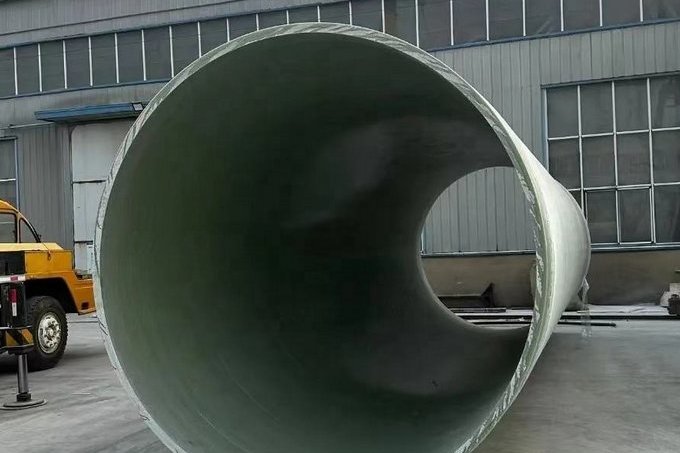
FRP/GRP pipe is specified as a 50-year material, and in most chemical and municipal services it earns that number. When a GRP line does fail early, the failure is almost never the load-bearing laminate — it is the corrosion barrier, a joint, or the crown of a gravity line that spends its life partly full. Owners then face the same question the steel and concrete world has faced for decades: does the pipe still carry load, and can it be relined instead of excavated? For FRP, cured-in-place pipe (CIPP) is increasingly the answer, but the design maths, the cure temperatures and the acceptance tests all interact with the host laminate in ways that are specific to composites. This guide covers the degradation mechanisms that trigger rehabilitation, the condition data you need before choosing a method, the ASTM F1216 Appendix X1 thickness design with a worked example, cure schedules, acceptance testing, and the services where relining an FRP pipe is the wrong decision.
1. Why FRP/GRP Pipe Deteriorates Before Its Nominal 50 Years
A filament-wound GRP pipe is a sandwich of functions, not a homogeneous material. The inner surface is a resin-rich corrosion barrier — typically a C-glass or synthetic veil plus two or three layers of chopped-strand mat, giving roughly 2.5 mm of resin-dominated laminate with a glass content below about 30% by weight. Behind it sits the structural laminate, wound at the angles needed to carry hoop and axial stress, and finally an outer resin-rich layer that protects against groundwater and UV.
The corrosion barrier is designed to be the sacrificial element. Its allowable strain is deliberately lower than the structural laminate's: ASTM D3299, the filament-wound tank standard, requires a hoop strain limit of 0.1%, and ASME RTP-1 caps corrosion-barrier tensile strain at roughly 0.10–0.13% under sustained load and 0.20% under intermittent load, with design factors of 10 and 5 respectively. Those limits exist so the resin matrix never cracks — because once the barrier crazes, the aggressive fluid reaches the load-bearing glass, and the pipe's remaining life is measured in months rather than decades. Deterioration therefore almost always begins as a chemistry problem that becomes a structural problem later.
Four mechanisms account for most field failures:
- Chemical attack on the barrier. Hot concentrated acids, hypochlorite-rich streams, oxidising bleaches and aromatic solvents attack the resin, causing softening, blistering and loss of the resin-fibre bond. The surface whitens, fibres bloom and the barrier erodes unevenly, thickest attack usually at the liquid-vapour interface where concentration and temperature are worst.
- Crown attack in gravity sewers. In partly filled lines the crown is not usually wetted; condensation of H2S-bearing vapour forms a thin acidic film, and the vapour space above the flow is where softening and loss of section first appear. Inspections that only look at the invert miss exactly the zone that governs.
- Joint and fitting failures. Gasket displacement, thrust-block movement, spigot cracking from over-insertion, and under-cured or porous butt-and-wrap laminates. Local failures like these are repair jobs, not relining jobs, and mixing the two up wastes the client's budget.
- External and mechanical damage. Ground movement and differential settlement, third-party excavation, abrasion from slurries at elbows, and above-ground sections that lose their UV protection and go chalky.
| Evidence found on site | Most likely mechanism | Typical first response |
|---|---|---|
| Softening, whitening or fibre bloom at the crown, plus sharp smell at manholes | Acidic condensate attack on the corrosion barrier in the vapour zone | Full-length relining (CIPP or sliplining) — the damage is continuous, not local |
| Blistering and delamination in a band around the liquid-vapour interface | Chemical permeation and osmotic blistering of the barrier | Chemical review + relining with a resin qualified for the actual chemistry |
| Hard, locally cracked surface with exposed white fibres at one location | Mechanical impact or point loading from a rock in the bedding | Cut out and laminate a local repair sleeve |
| Weeping at a joint or flange only under pressure | Gasket, bolt torque or joint laminate defect | Re-make the joint; do not reline a single joint's worth of damage |
| General abrasion at the invert, polished surface, measured thinning | Slurry or high-velocity solids abrasion | Relining if the thinning is trending; replace if wall loss is already large |
One practical point for procurement: the design-life promise on an FRP pipe datasheet assumes the barrier is intact. Every rehabilitation decision should therefore be based on measured remaining section and measured surface chemistry, not on installation date or nominal pressure class.
2. Condition Assessment: The Data You Need Before Choosing a Method
Two data sets decide the method: geometry and remaining structure. Geometry comes from a cleaned-line CCTV survey coded to a recognised system (NASSCO PACP or the WRc defect coding it derives from), which records the exact internal diameter, ovality, local deformation, offset joints, intruding laterals and any collapse or debris still in the line. Structure comes from nondestructive testing of the laminate.
- Ultrasonic thickness mapping. Grid the pipe at crown, springlines and invert at 1–2 m intervals and at every fitting. FRP is layered and attenuating, so the technique needs a transducer and setup matched to the composite, but it is the only field method that quantifies hidden thinning.
- Barcol hardness. Compare readings against the values the pipe achieved when new, or against a sample cut from an undamaged section of the same pipe. A soft surface reading plus visual bloom is the classic under-cured or chemically degraded barrier signature.
- Hammer tap (about 4 oz) and visual survey of the bore. Fast screening for delamination and joint separation — a dead tap where a sound tap is expected marks a delaminated zone.
- Thermography. Useful above ground and on accessible buried lengths to locate moisture pathways and liner detachment.
- Effluent analysis, not just the datasheet fluid. pH, temperature, oxidant residual (free chlorine or hypochlorite), solvent content and solids abrasion potential. Relining resin selection follows the fluid that is actually in the pipe, including intermittent cleaning and disinfection doses.
Ovality deserves special attention because it enters the liner design as a cubed term. The ovality reduction factor in ASTM F1216 Appendix X1 is C = [(1 − Δ/100) / (1 + Δ/100)²]³. At 2% ovality, C = 0.84; at 5%, C = 0.64; at 10%, C = 0.41. A pipe that has ovalised to 10% therefore needs a liner more than 50% heavier than the same pipe at 2% — which is why an accurate diameter and ovality measurement on day one is worth more than any amount of conservative guessing later.
3. Repair, Reline or Replace: A Decision Frame
Relining wins when the host pipe still provides a continuous, roughly circular constraint and the damage is distributed along the length. Replacement wins when the line has collapsed, when geometry has moved beyond what a liner can cope with, or when a pressure class must be restored that relining cannot deliver.
| Condition of the GRP line | Rehabilitation that normally fits | Reason |
|---|---|---|
| Local crack, impact damage, one bad joint; remaining laminate sound | Cut-out and laminate repair, or a short sectional CIPP sleeve | Fully deteriorated design not required; the host pipe still carries load |
| Distributed barrier loss, less than about 30% of structural wall consumed, ovality below 5% | Full-length CIPP, partially deteriorated design basis | Host pipe carries the external ground load; liner handles chemical duty and lost section |
| Heavy wall loss, deep ovality, cracked but stable ring | Full-length CIPP, fully deteriorated design basis (ASTM F1216 X1.1–X1.4 all satisfied) | Liner designed as an independent tube resisting groundwater, soil and traffic load |
| Large diameter, long runs, adequate access at both ends, good remaining section | Sliplining with a new GRP or HDPE carrier and annulus grout | Restores flow and pressure capacity; requires a diameter sacrifice and open pits |
| Collapse, severe deformation, offset beyond liner tolerance | Excavate and replace | No liner can be reliably installed in an obstructed, non-circular bore |
| Pressure service above a few bar where the full class must be restored | Replace, or trenchless replacement with a new pressure-rated GRP/HDPE line | CIPP does not reinstate a high pressure class |
That last row is the one most often got wrong. CIPP is established practice for gravity and low-pressure systems, and the design appendix of ASTM F1216 does include a pressure-pipe condition, but a relined GRP line is not a PN 16 GRP line. Where a process line must return to a certified pressure class, the honest options are a new pressure-rated carrier installed by sliplining or pipe jacking — the sequence, jacking-force calculation and grouting details are covered in our GRP pipe jacking and sliplining guide — or full replacement with new pipe from our filament-wound FRP/GRP process pipe range.
4. CIPP Systems and the Standards That Apply
CIPP is not one product. It is a family of resin-impregnated liners installed by different mechanics and cured by different routes, and the applicable standard follows the installation method:
| Installation route | Standard | Where it fits |
|---|---|---|
| Inversion, cured in place (water or air pressure turns the liner inside out through the host pipe) | ASTM F1216 | Most common route; strong expansion control and low friction; needs a header or scaffold to build the inversion head |
| Pulled-in-place thermoset liner, inflated with a calibration hose | ASTM F1743 | Better where access is awkward or the liner is stiff; requires two access points |
| Pulled-in-place glass-reinforced (GRP) CIPP | ASTM F2019 | Structural liners where higher flexural modulus per unit thickness is needed, i.e. thinner walls for the same DR |
| Sectional/spot repair sleeve, inverted at a local defect | ASTM F2599 | Isolated cracks and joint defects; not a substitute for a continuous liner |
| Lining of drains and sewers with cured-in-place pipe | ISO 11296-4 | European specification route, often required alongside ASTM on dual-standard projects |
Whatever the route, one design philosophy is common: in the fully deteriorated condition the liner is treated as a non-bonded, free-standing tube that must resist groundwater pressure, soil load and traffic load on its own. That is why the design method uses a buckling equation rather than a hoop-stress equation, and why the properties of the cured liner — not the resin ratio of the wet liner — are the design inputs.
5. Liner Construction and Resin Selection for Chemical Service
A CIPP liner is a composite bag: a reinforcement (needle-punched polyester felt, or felt combined with glass fibre) plus a thermoset resin plus an inner and outer plastic coating that keeps the resin in and the effluent out. Felt-only liners are the standard for gravity sewer service and are cheap and flexible, but they are weak in flexure. Where the design calls for a thin structural liner, a glass-reinforced liner qualified to ASTM F2019 is the better tool: the glass carries the flexural load, so the required flexural modulus at the required thickness is reached with less material and the finished wall is thinner, preserving flow area.
The resin system is the chemical decision, and it is the same family logic that applies to any FRP equipment:
| Liner resin | Practical service envelope | Choose it for |
|---|---|---|
| Isophthalic polyester | To about 60 °C; neutral to mildly aggressive water and sewage | Municipal gravity sewers, stormwater, non-aggressive process water — the economical default |
| Bisphenol-A vinyl ester | To about 90–100 °C depending on the resin grade and cure | Industrial effluent, hypochlorite and oxidising duties, dilute acids and alkalis, most chemical plant drainage |
| Novolac / epoxy vinyl ester | High-temperature and solvent-rich duties; verify against the supplier's chemical resistance table | Concentrated acids, aggressive solvent streams, high-temperature process drainage |
| Epoxy | Highest temperature capability with post-cure; slower and more costly to cure | Hot process lines where polyester and vinyl ester are marginal |
Three mechanical properties must appear in the purchase specification, because the design calculation is only valid if the delivered liner achieves them: short-term flexural modulus measured to ASTM D790 (common specifications require a minimum of 250,000 psi, about 1,724 MPa, with structural projects often specifying 400,000 psi / 2,758 MPa), short-term flexural strength also to ASTM D790 (commonly a minimum of 4,500 psi, about 31 MPa), and chemical resistance tested to the ASTM F1216 Appendix X2 procedure in the actual effluent, both with and without the plastic coating. Untested resin-plus-felt combinations should never be accepted on a chemical duty, even when the resin family looks right on paper.
6. Thickness Design with ASTM F1216 Appendix X1
The design method starts by classifying the host pipe. Partially deteriorated means the existing pipe still resists external ground loads and, after rehabilitation, will continue to do so; the liner then needs only to resist internal pressure and its own buckling under local conditions. Fully deteriorated means the host pipe cannot be relied on to carry external loads for the design life, so the liner becomes the structural pipe. The fully deteriorated condition requires all four equations below to be satisfied, and the governing (thickest) result is adopted.
| Equation | What it checks | Form (ASTM F1216 Appendix X1) |
|---|---|---|
| X1.1 | Buckling of the liner under groundwater pressure at the invert | P = [2·K·EL / (1 − ν²)] × [1 / (DR − 1)³] × (C / N) |
| X1.2 | Tensile stress at the point of maximum curvature in an ovalised ring | 1.5(Δ/100)(1 + Δ/100)·DR² − 0.5(1 + Δ/100)·DR = σL / (P·N) |
| X1.3 | Buckling under soil plus live load at the crown | qt = (1/N)·[32·Rw·B′·E′s·C·(EL·I/D³)]1/2 |
| X1.4 | Minimum wall stiffness, so the liner cannot flex into gaps at joints and connections | E·I / D³ = E / [12·(DR)³] ≥ minimum stiffness |
The parameters are the ones that decide how much material the client buys:
- DR — dimension ratio, D/t. The smaller the DR, the thicker the liner, and because it appears cubed in X1.1 the pressure capacity changes very quickly.
- EL — long-term (time-corrected) flexural modulus. The usual design convention is to take 50% of the short-term ASTM D790 test value as the 50-year design value. Using short-term modulus in design is a common and expensive-by-surprise error in reverse: it makes a liner look adequate on paper that will buckle in service.
- σL — long-term flexural strength, again normally 50% of the short-term test value.
- K — buckling restraint enhancement factor. Test calibration on 49 liners with DR from 30 to 90 found K between 6.5 and 25.8; the value used for design is 7.0, effectively the lower 90% confidence limit.
- N — safety factor, conventionally 2.0. ν — Poisson's ratio, 0.3 for these laminates.
- C — ovality reduction factor described in section 2. Rw, B′, E′s — water buoyancy factor, coefficient of elastic support and soil modulus from the geotechnical report.
7. Worked Example: DN600 GRP Sewer at 4 m Cover
Take a 600 mm internal diameter GRP gravity sewer, 4.0 m of cover, groundwater standing 2.5 m above the crown, an existing ovality of 5% and HS-20 traffic loading. The liner is a glass-reinforced vinyl ester CIPP with a short-term flexural modulus of 2,800 MPa, so EL = 1,400 MPa. The head of groundwater at the invert is approximately 3.1 m, giving P = 0.031 MPa.
Applying X1.1: 2KEL/(1 − ν²) = 2 × 7 × 1,400 / 0.91 = 21,538 MPa; C/(N·P) = 0.64 / (2 × 0.031) = 10.3; the product is 2.22 × 10⁵, its cube root is 60.6, so DR − 1 = 60.6 and DR = 61.6. Adopting DR 60 as a round design value gives a liner thickness of 600 / 60 = 10 mm. X1.4 then has to be checked for the gaps at joints and lateral connections; and X1.3, the crown load case, will usually govern for shallowly buried traffic sewers — for reference, a published municipal specification for a 100 mm liner at roughly 1.4 m cover with HS-20 loading reported X1.1 requiring DR 66.7, X1.3 governing at DR 58.0 (a 1.8 mm liner) and X1.4 requiring DR 60.6. That comparison is the key commercial insight: the crown load case, not the groundwater case, is what sizes most buried sewer liners.
| Nominal bore | Liner thickness at DR 62 | Liner thickness at DR 55 (heavier crown load / deeper cover) |
|---|---|---|
| DN 300 | 5 mm | 6 mm |
| DN 400 | 7 mm | 8 mm |
| DN 500 | 9 mm | 10 mm |
| DN 600 | 10 mm | 11 mm |
| DN 800 | 13 mm | 15 mm |
| DN 1000 | 17 mm | 19 mm |
| DN 1200 | 20 mm | 22 mm |
Note the shape of that table: holding DR constant makes the liner thickness rise linearly with diameter, so a DN 1200 reline is not "a bit more expensive" than a DN 300 reline — it is four times the material, with proportionally longer cure times as well, because cure time scales roughly with the square of wall thickness. This is why large-diameter relining projects are usually quoted per metre with a thickness stated, never as a lump sum.
8. Installation Hold Points and Cure Schedules
Rehabilitation quality is won or lost at four hold points. First, pre-cleaning: debris, roots and scale must be removed and the line re-surveyed, because a liner placed over an obstruction wrinkles and never recovers. Second, wet-out control: resin content, storage temperature (thermally cured liners are kept chilled so they do not start to cure in transit) and the time between wet-out and installation all need recording on the batch sheet. Third, insertion and inflation: inversion head or pull-in tension, lubricant, and a dimple at every lateral that confirms the liner pressed fully into the connection. Fourth, cure and cool-down.
| Cure method | Typical temperature | Typical duration (planning ranges) | Notes |
|---|---|---|---|
| Hot water | 60–80 °C; ASTM F1216 practice retains the water at about 80 °C for 90 minutes before the post-cure hold | DN 300–600: 4–7 h; DN 700–1200: 7–11 h | Most forgiving method; needs boiler, circulation pump, and temperature logging of the incoming and outgoing water |
| Steam | About 82–120 °C | DN 300–600: 2–4 h; DN 700–1200: 4–6 h | Faster, less water; condensate management and hot-spot control are critical |
| UV light train | Ambient resin temperature with a traversing light source | Traverse at roughly 0.8–1.5 m/min for DN 200–400, falling to 0.2–0.5 m/min at DN 1600–2200 | Very fast and leaves an uncured liner workable until the light passes; needs a UV-specific resin |
After cure, the liner must be cooled to below about 38 °C before the ends are opened, trimmed and the line returned to service, otherwise the liner shrinks away from the host pipe as it cools and the ends pull back.
FRP-specific trap: the cure temperature can exceed the heat deflection temperature of the host pipe. Isophthalic polyester GRP is typically limited to about 60–70 °C in continuous service, vinyl ester to about 90–100 °C, and epoxy GRE to 110–150 °C. Steam curing at 120 °C inside an isophthalic host pipe is therefore a resin-relaxation event for the host laminate, not just a curing event for the liner. Before specifying a steam cure, confirm the host pipe's resin system and HDT, monitor host-pipe temperature at the crown, or switch to hot water at a lower temperature with a longer hold, or to UV curing which never heats the host laminate significantly.
9. Acceptance Testing, Field Samples and Documentation
The liner is accepted on evidence, and the evidence is largely four items: samples, a closed-circuit television survey, a geometry check and a tightness test.
| Check | Method | Typical acceptance basis |
|---|---|---|
| Wall thickness and flexural properties | Test coupons cut from the liner at the ends of the run, tested to ASTM D790 | Achieves the design flexural modulus and strength; thickness not below the specified value at any test point |
| Visual condition of the finished bore | Post-lining CCTV with the same coding system as the pre-survey | No wrinkles, blisters, delamination or gaps exceeding the project's defect standard; full circumferential seating at connections |
| Roundness / deflection | Rigid mandrel or laser profilometry | Pass a mandrel sized to the specified deflection limit — commonly a bore about 5% smaller than nominal, or as stated in the specification |
| Tightness (gravity lines) | Low-pressure air test with ends plugged, or water exfiltration/infiltration measurement | Air test typically run at 1–3 psi with an allowable loss stated in the specification; water test within the local infiltration allowance |
| Tightness (pressure service) | Hydrostatic test before return to service | Held at the specified test pressure with no loss, using the procedure in our FRP pipe pressure testing guide |
Two documents are worth insisting on in the contract: a temperature log covering the whole cure (incoming and outgoing water or steam temperature, plus sensors between the liner and the host pipe at both ends), and a follow-up CCTV survey six to nine months after commissioning, to catch resin shrinkage and any host-pipe movement while it is still the contractor's problem.
10. Styrene, Confined Space and the Specification Checklist
Styrene is the dominant volatile emission in a polyester or vinyl ester CIPP operation, and it is the reason relining attracts attention from building occupants as well as from the site crew. The exposure limits are not generous: the OSHA permissible exposure limit is 100 ppm as an 8-hour time-weighted average, with a 200 ppm ceiling and a 600 ppm peak allowed for up to 5 minutes in any 3 hours; NIOSH recommends 50 ppm TWA with a 100 ppm short-term limit and lists 700 ppm as immediately dangerous to life or health; the ACGIH threshold limit value is 10 ppm TWA with a 20 ppm short-term limit. The three that matter on site are the ACGIH values for planning, the OSHA values for legality, and the fact that styrene vapour migrates through the sewer network into connected buildings — which is why cure selection, odour control and neighbour notification belong in the method statement. Practical controls: forced ventilation of the work section, extraction at the curing access points, entry only with atmospheric monitoring and a permit, and, where odour-sensitive buildings are connected, choosing a lower-styrene or UV-cure route.
- Condition survey report: CCTV with coded defects, measured internal diameter, ovality in the damaged zone, UT thickness map, Barcol readings against baseline
- Effluent analysis with the liner supplier's chemical resistance statement for the actual chemistry, temperature and oxidant residual
- Design basis statement: partially or fully deteriorated, the equations used, and the assumed long-term modulus and strength
- Specified liner construction: felt or glass-reinforced, resin system, thickness or DR, and the ASTM D790 test values required of field samples
- Overall service life of the FRP line after relining
- Cure method, temperature and duration; host-pipe resin system and HDT confirmed against the cure temperature
- Acceptance criteria: sample testing, mandrel size, air or water tightness limits, and CCTV defect thresholds
- Documentation package: temperature logs, batch records, sample test reports, pre- and post-CCTV, and the six-to-nine-month reinspection
Related reading: our custom filament-wound FRP/GRP process pipes and FRP pressure pipe ranges, the GRP pipe jacking and sliplining guide for trenchless replacement, the GRP pipe specification guide, FRP pipe support spacing and hanger design, and FRP tank repair and relining for the vessel-side equivalent.
Need help selecting FRP products?
Our engineers answer technical questions free of charge.
Ask an Engineer on WhatsApp