
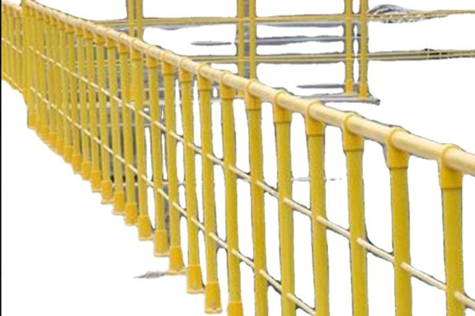
Walk the tank farm of a chemical plant commissioned in the 1990s and the access hardware tells you its age. Every tank carries a galvanised cage ladder, and every one of those cages now sits on a compliance clock: under the current OSHA walking-working surfaces rules a cage installed today does not count as fall protection, and by 18 November 2036 a cage will not count on any fixed ladder over 24 feet. Owners are therefore replacing cages with rail-guided ladder safety systems - and a growing share of the new ladders and cages are pultruded FRP rather than galvanised steel, because the same plants that have to solve the fall-protection problem also have chlorides, acid vapours and live conductors to deal with.
This article works through both halves of that decision: what the codes actually demand of a fixed ladder, and how to size a pultruded ladder so that it satisfies them. The material argument itself is set out in our FRP vs wood vs aluminium comparison; the deck surfaces that normally sit at the top of the ladder are covered in our stair tread slip resistance guide.
1. When a Fixed Ladder Should Be Pultruded FRP
The case for FRP on access structures is corrosion economics, not novelty. Galvanised steel in a chloride environment loses its zinc at roughly 5-15 µm per year in a mild industrial atmosphere and far faster in a wet chloride one, which puts a 60-80 µm coating out of service long before the structure is 20 years old. Pultruded FRP is unaffected by chlorides, dilute acids and alkalis, needs no re-coating, and weighs about a quarter of the steel equivalent - a 6 m two-stile ladder that would take three people to lift in steel can be carried by two.
Two further conditions push the decision:
- Dielectric isolation. A ladder standing on a substation structure, in a cable gallery or beside live busbars must not become a path to earth. FRP does not conduct, which removes an earthing and isolation problem that a steel ladder creates by default.
- Hot work. Welding a steel ladder into a refinery, tank farm or solvent plant needs a hot work permit, a fire watch and a gas test. A bolted pultruded ladder needs none of that, which in a live plant is often worth more than the material cost difference.
What FRP does not solve is temperature and fire. Standard polyester pultrusions are limited to roughly 80-100 °C continuous, vinyl ester systems to about 110-120 °C, and stiffness falls as the service temperature climbs towards the resin's heat deflection point. Inside a fire compartment or on an escape route, ask for a fire-retardant resin system with a declared classification (ASTM E84 Class 1, or EN 13501-1 B-s1,d0) and note that the classification applies to the profile as tested, not to the family of products called FRP.
2. Two Rulebooks, Two Different Philosophies
Almost every fixed ladder specification in the world is written against one of two frameworks, and they do not say the same thing.
- OSHA 29 CFR 1910.23 sets prescriptive dimensions in inches - rung pitch, clear width, clearance behind the rung, side-rail extension - and is applied to general industry in the United States. The fall-protection duty sits in a separate standard, 1910.28, and the criteria for the systems themselves in 1910.29.
- EN ISO 14122-4 is the machinery-access standard. It covers fixed ladders that form part of a permanent means of access to machinery or plant, is used across the EU, the UK, the Middle East and much of Asia, and is supported by the rest of the series: 14122-1 on choosing the means of access, 14122-2 on working platforms and 14122-3 on stairs and guardrails.
The philosophical difference matters more than the numbers. OSHA triggers fall protection at a fixed height - more than 24 ft (7.3 m) above a lower level - and then lets the calendar dictate what type of system is acceptable. EN ISO 14122-4 requires protection from a fall height of 3,000 mm, treats a cage as the default solution where one can be fitted, and reserves guided fall arresters for low-frequency or specialised access.
The practical trap is a project that is bought to ISO and audited to OSHA. A 4 m ladder with a cage satisfies EN ISO 14122-4 and fails 1910.28(b)(9) the moment it is installed, because a cage no longer qualifies. Resolve that at the drawing stage, not at the site: either lengthen the design so that a rail-guided system makes sense, or write the fall-protection type into the purchase order explicitly.
3. The Dimensions That Actually Get Measured
Inspectors measure four things before they look at anything else: rung pitch, clear width, clearance behind the rung, and the extension of the side rails above the landing. The two frameworks overlap enough to design one ladder for both markets - but only if you aim at the tighter value in each row.
| Dimension | OSHA 1910.23 (general industry) | EN ISO 14122-4 | Design value that satisfies both |
|---|---|---|---|
| Rung pitch, centre to centre | 10-14 in (254-356 mm); ANSI A14.3 fixes 12 in | Constant, 225-300 mm | 280 mm (11.0 in) |
| Clear width between stiles / rung width | min 16 in (406 mm) clear rung width | 400-600 mm; 300-400 mm only where the environment makes 400 impossible | 450 mm |
| Clearance behind the rung | min 7 in (178 mm) from rung centreline; 4.5 in for elevator pits | 200 mm behind the ladder, 150 mm where a pipe or duct crosses | 200 mm |
| Clearance in front of the ladder | 30 in (762 mm) climbing-side clearance on vertical ladders | 650 mm; 600 mm where a pipe crosses | 762 mm |
| Side rails above landing | extend 42 in (1,067 mm) above the landing | Step-out of 500-700 mm at the arrival area | 1,100 mm, with the step-out checked separately |
| Top rung position | Level with the landing for top access | Top rung at the walking surface of the arrival area | Level with the landing |
| Step-across, through ladder | 7-12 in (178-305 mm) from rung centreline to the nearest edge | Covered by the 650 mm front clearance | Measure on site, not from the drawing |
| Step-across, side-step ladder | 15-20 in (381-508 mm) to the platform edge | Step-out 500-700 mm | 500 mm |
| Rung walking surface | Slip-resistant treatment required | Flat walking surface - a plain round rung is not acceptable | Flattened and grooved round tube, or rectangular section |
| Pitch | Not greater than 90° from horizontal | Vertical or near-vertical | Vertical |
Three of these cause most of the site arguments. First, pitch is measured at the top of the ladder, not the bottom; stringers are routinely cut to length on site and the last two rungs end up at a different spacing from the rest. Second, the clear width is measured between the running surfaces, so a cage hoop, a rail bracket or a conduit fixed inside the stringers can take a compliant ladder out of compliance. Third, the rung surface is easy to get wrong across markets - a plain round rung is common in older steel ladders and is not acceptable under EN ISO 14122-4.
4. Fall Protection Above 24 Feet: The Cage Is on a Timeline
The duty to provide fall protection on a fixed ladder attaches when the ladder extends more than 24 ft (7.3 m) above a lower level. Which system is acceptable then depends entirely on the ladder's date and history, and the four sub-paragraphs of 1910.28(b)(9)(i) form a timeline rather than a single rule.
| Ladder status | What the rule requires | Citation |
|---|---|---|
| Installed before 19 November 2018 | Personal fall arrest system, ladder safety system, cage or well | 1910.28(b)(9)(i)(A) |
| Installed on or after 19 November 2018 | Personal fall arrest system or ladder safety system only - a cage or well does not satisfy the rule | 1910.28(b)(9)(i)(B) |
| Any replacement of the ladder, cage, well, or any portion of a section | Personal fall arrest system or ladder safety system must be installed at replacement | 1910.28(b)(9)(i)(C) |
| Every fixed ladder over 24 ft, from 18 November 2036 | Personal fall arrest system or ladder safety system - the cage and well option expires | 1910.28(b)(9)(i)(D) |
Sub-paragraph (C) is the one that catches maintenance budgets. A rusted cage section that gets swapped out is not a repair; it converts that ladder into a current-code installation, and the fall protection has to be upgraded at the same time. Planning to replace ladder sections one at a time over ten years is a way of paying for the retrofit twice.
Two points are routinely misread in the other direction. First, OSHA never requires a cage to be removed. An existing cage may stay indefinitely; it simply stops counting as fall protection, and many plants choose to keep it and install a rail-guided system inside it. Second, below 24 ft no fall protection is mandated by 1910.28(b)(9) - but a fall from 20 ft is still a fatal fall, which is why EN ISO 14122-4's 3,000 mm trigger is the better design instinct even on a US project.
Two spacing rules apply to tall multi-section access:
- Where a cage or well covers offset sections, landing platforms at intervals of no more than 50 ft (15 m) are required.
- Where a ladder safety system or personal fall arrest system spans multiple sections, rest platforms at intervals of up to 150 ft (45.7 m) are required.
The single most-inspected detail on a tall ladder is not the fall protection at all: it is the ladderway opening at the top, which needs a guardrail system and toeboards on all exposed sides and either a self-closing gate or an offset arrangement. Get that wrong and the cage debate becomes academic.
5. Cage Geometry to EN ISO 14122-4
If the specification calls for a cage - common in the Middle East, Asia and on machinery access - these are the numbers that define it:
- Hoop diameter: 650-800 mm, measured to give a free passage around the climber.
- Hoop spacing: not more than 1,000 mm between hoops; some manufacturers still quote 1,500 mm, so check the product's declaration rather than the sales drawing.
- Vertical bars: at centres not exceeding 300 mm, so that no opening between bars exceeds 400 mm.
- Cage start height: the cage begins at 2,200-3,000 mm above the walking surface, not at the first rung.
- Maximum single cage run: 10,000 mm, after which a rest platform or an offset with a landing is required.
- Step-out at the top: 500-700 mm, and it may be arranged to the side of the cage. In practice the lateral step-out is the better detail, because it lets the climber transfer weight without leaning backward.
- Wall anchors: at centres not exceeding 2,000 mm, with one within about 300 mm of every stringer joint.
- Use restriction: one person per 2.5 m of cage ladder at a time.
A cage is a container, not an arrester. It stops a climber falling backwards; it does nothing to absorb the energy of a fall, and it is why the standards have moved towards rail-guided systems for any ladder that is climbed routinely.
Read the rest of the standard together with this section. EN ISO 14122-4's position is that the cage is preferred because it is always present and works without the climber doing anything, while a fall arrester only works if the harness is worn and connected correctly. That logic holds for a ladder climbed twice a year. It stops holding for a ladder climbed twice a week with tools, where the rigid rail and guided arrester is both safer and, over a 20-year life, cheaper than the harness discipline a cage-based design demands.
6. Which Pultrusions Go Into a Ladder
A ladder is a small structure with a lot of different load paths, and trying to build it from one profile is a false economy. The table below is the bill of sections behind a typical 450 mm wide access ladder.
| Component | Typical pultruded section | Why that section |
|---|---|---|
| Stile / side rail | 60 × 60 × 5 mm square tube, or a 75 × 26 mm oblong | Bending stiffness in two directions; the square tube also gives a clean face for the wall bracket |
| Rung | 33 mm round tube flattened and grooved on top, or 40 × 20 mm rectangular tube on edge | Flat walking surface per EN ISO 14122-4; the rectangular section is roughly twice as stiff across a wide ladder |
| Cage hoop | Bent 25 × 25 × 1.5 mm square tube, or 80 × 8 mm flat bent on the flat | Light, easy to bend to a 650-800 mm diameter, and stiff enough in hoop compression |
| Cage vertical bar | 18 × 2 mm round tube or 30 × 3 mm flat | Fills the 400 mm opening limit at 300 mm centres without adding wind area |
| Wall bracket | Pultruded angle 50 × 50 × 6 mm or 75 × 40 × 6 mm | Two-bolt fixing to the structure and one to the stile; the thicker wall takes the bolt bearing load |
| Handrail / top rail | 50 mm round or 50 × 50 × 5 mm square tube | Matches the walkway handrail at the landing so the whole access route looks and behaves the same |
| Kick plate | 100 × 6 mm flat, or a 40 × 40 × 5 mm angle | 100 mm minimum height at the platform edge |
One specification detail carries more weight than the geometry: glass content. Structural pultrusions should be 60-70 % glass by weight; the cheaper "commercial" grade at around 50 % has noticeably lower modulus and is the reason some pultruded ladders feel flexible in service. Ask for the glass content and the laminate schedule, and check that the supplier's declared modulus comes from a test on the actual profile, not from a generic data sheet.
7. Stiffness, Not Strength, Sizes a Pultruded Ladder
This is where FRP design differs from steel design, and where most pultruded ladders are under-built. A pultruded profile has useful strength - 200-400 MPa in tension along the fibres - but its modulus is roughly a tenth that of steel. For the same section, an FRP member deflects about nine times as much at the same load. Limit states that steel design never checks suddenly govern.
| Property | Pultruded FRP, polyester | Pultruded FRP, vinyl ester | Carbon steel | 6061-T6 aluminium |
|---|---|---|---|---|
| Tensile modulus | 20-25 GPa | 25-30 GPa | 210 GPa | 69 GPa |
| Density | 1.80-1.95 g/cm³ | 1.85-2.00 g/cm³ | 7.85 g/cm³ | 2.70 g/cm³ |
| Flexural strength | 200-400 MPa | 250-450 MPa | 250 MPa (yield) | 240 MPa |
| Relative deflection, equal section and load | about 9 × | about 8 × | 1 × | about 3 × |
| Thermal expansion | 8-12 × 10-6/K | 10-14 × 10-6/K | 12 × 10-6/K | 23 × 10-6/K |
Take the rung first, because it is the member a person actually loads. EN ISO 14122-4 proof-loads the rung at 1.5 kN without permanent deformation. Apply that at mid-span of a 500 mm clear width with a design modulus of 22,000 MPa and the deflection follows from δ = F L³ / (48 E I):
- 33 mm round tube, 3 mm wall - I ≈ 32,100 mm4, δ ≈ 5.5 mm, which is about L/91. The rung passes the load test but feels soft underfoot.
- 40 × 20 × 3 mm rectangular tube on edge - I ≈ 60,800 mm4, δ ≈ 2.9 mm, about L/171.
- 50 × 12 mm flat on edge - I ≈ 125,000 mm4, δ ≈ 1.4 mm, about L/352.
The conclusion is counter-intuitive if you are used to buying round-rung steel ladders: on an FRP ladder wider than about 450 mm, specify a rectangular or flat-on-edge rung. A round rung is acceptable in a narrow ladder and marginal in a wide one.
The stile check follows the same logic, and it is the bracket spacing - not the load - that decides the section. With the 1.5 kN shared between two stiles (750 N each), a 1,500 mm bracket spacing and a serviceability limit of L/200 (7.5 mm), the required second moment of area is I = F L³ / (48 E δ) ≈ 320,000 mm4. A 60 × 60 × 5 mm square tube provides about 559,000 mm4 and passes comfortably; a 50 × 50 × 5 mm tube provides about 307,000 mm4 and does not. Push the bracket spacing out to 2,000 mm and the requirement rises by a factor of 2.4, which takes the 60 mm tube out of the running as well.
Two reductions belong in any honest FRP stiffness check. Creep: pultruded laminates deflect progressively under sustained load, and FRP design guides commonly apply a factor of about 2 to the long-term check. A rung is an intermittent load, but a rail-guided fall arrester imposes a permanent pre-load on the ladder, which is one more reason to add stiffness rather than trim it. Temperature: at 60 °C the modulus of a polyester pultrusion may be 10-20 % below its 23 °C value, so a ladder in a hot process area should be checked with the reduced figure.
8. Assembly Details That Decide Service Life
FRP ladders are bolted, not welded, and the joint rules are stricter than they look.
- Fasteners: A4-70 (316) stainless steel for anything outdoors or in a chemical atmosphere. Where the ladder bolts to a steel structure, use an isolating washer on the steel side; the FRP is inert but the structure is not.
- Hole clearance: +1.0 to +2.0 mm on the bolt diameter. Pultrusions do not yield to a forced bolt; they split.
- Edge and end distances: keep edge distance at least 2 bolt diameters and spacing at least 3 diameters. Inside those limits, pultruded joints fail by shear-out or bearing well before the laminate reaches its tensile strength.
- Washers and torque: use washers at least 3 bolt diameters across, and tighten to a value that compresses without crushing - typically 15-25 N·m for an M10 bolt into a pultruded section. Over-torqued joints relax within weeks and then work loose, which shows up later as a rattling ladder and elongated holes.
- No site bonding. Adhesive joints need controlled temperature, humidity, gap and clamping pressure. Shop-bonded joints are fine when the fabricator has a qualified procedure; site-bonded joints on a ladder are not.
- Cutting and drilling: carbide-tipped saw, sharp bit, moderate speed, no flame cutting, and dust extraction - the dust is an irritant.
- Seal every cut end. Exposed fibre wicks water along the laminate by capillary action, and a soaked stringer end is the beginning of a delamination. A brush of compatible resin on each cut is a two-minute job that adds years.
- UV: pultrusions should carry a UV-stabilised surfacing veil. On an outdoor ladder, a light colour runs several degrees cooler in service and chalks more slowly than a dark one.
9. Installation Sequence and Handover
- Fix the fall-protection type before ordering. Cage, rail-guided system or personal fall arrest changes the stringer layout, the bracket loads and the price. Deciding it after the ladder arrives means re-drilling stringers on site.
- Survey the wall or shell for plumb and for anchor embedment. A deviation of more than about 10 mm over 3 m should be taken up by packers, never by winding the bolts tight against the pultrusion.
- Set out the ladder centreline and mark anchor positions at no more than 2,000 mm centres, with one within 300 mm of every stringer joint.
- Assemble on the ground. Stringers, rungs and cage hoops go together flat, where pitch and squareness can be measured properly, before anything is lifted.
- Check the rung pitch along the full length and record it. This is the measurement an inspector repeats, and it is nearly impossible to correct once the ladder is bolted up.
- Lift and bolt from the bottom up, checking plumb every second bracket. Adjust packers rather than bolt tension.
- Install the fall protection and, if applicable, the cage, then verify hoop spacing, vertical bar openings and the step-out at the top.
- Guard the ladderway opening: guardrail system and toeboards on all exposed sides, plus a self-closing gate or an offset. Confirm the top rung sits level with the landing and that the step-across is within limits.
- Torque, record and hand over: torque log, anchor positions, as-built drawing - and the date of installation. That date decides whether the ladder is governed by (b)(9)(i)(A) or (B) for the next two decades, and a plant that cannot prove it will be treated as if the stricter rule applies.
10. Specification Checklist and Common Mistakes
| Specify this | Why it matters |
|---|---|
| Governing standard and the fall-protection type | Fixes the stringer layout, bracket loads and the compliance route |
| Fall height and lowest landing level | Determines whether the 24 ft duty and the 3,000 mm trigger are in play |
| Rung pitch, clear width and both clearances | The four dimensions an inspector measures first |
| Rung section and walking surface | A flat, grooved or rectangular surface is required, not a plain round rung |
| Glass content and laminate schedule | 60-70 % glass by weight is structural; 50 % is not |
| Design modulus and the deflection limit | State the check explicitly, including creep and service temperature |
| Resin system, fire classification, UV finish | Determines chemical resistance, code acceptance and appearance over time |
| Fastener grade, washer size and torque | Prevents crushed laminates and loose joints |
| Cage geometry, if fitted | Hoop diameter, hoop spacing, bar openings, start height, step-out |
| Ladderway opening protection | Guardrail, toeboard and self-closing gate or offset at the top |
| Test and handover documents | Proof-load record, torque log, as-built drawing and installation date |
The mistakes that show up most often, in rough order:
- Buying a cage on a new ladder today and assuming it satisfies 1910.28. For ladders installed on or after 19 November 2018, it does not.
- Replacing a damaged cage or ladder section without upgrading the fall protection, which triggers the requirement under (b)(9)(i)(C) whether or not anyone intended it.
- Sizing the pultrusion from a steel or aluminium modulus, or accepting a supplier's "FRP ladder" without a deflection check.
- Specifying a 50 mm square stringer at 2,000 mm bracket spacing because it looks adequate in bending stress.
- Using a round rung on a wide ladder, then dealing with complaints about a springy climb.
- Cutting stringers to length on site without re-checking pitch at the top, leaving the last rungs out of tolerance.
- Forgetting the ladderway gate at the top - the most frequently cited defect on an otherwise compliant ladder.
- Leaving cut ends unsealed, so water wicks into the laminate and the stringer end swells and delaminates.
HuanGang pultrudes the sections a fixed ladder is built from - stiles, rungs, cage hoops, brackets and the landing hardware around them - within our pultruded profiles and structural components range. The catalogue includes anti-slip GRP stair and handrail profiles for the landings and walkways, moulded SMC fittings for railing and handrail systems where a bolted corner is weaker than a moulded one, and moulded grating walkway and stair tread panels for the platform at the top. Send us the fall height, the governing standard, the service temperature and the structure you are fixing to, and we will return a section schedule with the deflection check worked through rather than a picture of a ladder. The wider design context for pultruded sections is in our pultruded profiles application guide.
Need help selecting FRP products?
Our engineers answer technical questions free of charge.
Ask an Engineer on WhatsApp