
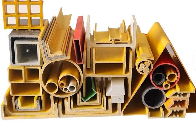
FRP grating and pultruded profiles leave the factory with a sealed, resin-rich surface. Every workshop operation — sawing panels to size, drilling clip holes, routing slots — cuts through that surface and exposes bare glass fibre ends. Get the tooling right and the machined part performs for decades; get it wrong and you get scorched resin, delaminated hole walls and a wicking path for exactly the chemical the part was chosen to resist. This guide sets out blade selection, drilling speeds and feeds, routing and waterjet parameters, dust control and edge-sealing practice for a fabrication shop working with molded and pultruded FRP.
1. Why Fibreglass Machining Behaves Nothing Like Metal
Three properties of FRP drive every parameter in this article. First, E-glass fibre is harder and more abrasive than most tool steels, and pultruded sections routinely carry 60–70% glass by weight along their axis — every second of cutting is effectively grinding hardened glass. Second, a thermoset matrix cannot deform plastically: there is no clean chip formation, only micro-fracture, so the debris is a fine abrasive powder rather than swarf, and it destroys a dull edge exponentially faster than steel does. Third, the resin is heat-sensitive: vinyl ester and polyester matrices lose strength and discolour well below red heat, so friction energy that a metal cut would shrug off can scorch the resin and leave a weak, powdering edge.
The practical consequences run against steel-shop habits. Higher cutting speed with a light, consistent feed usually beats slow speed with heavy feed, because heavy feed drives up thrust force at breakthrough — the main cause of exit-side delamination. Flood coolant, standard on metal, is frequently the wrong choice on FRP because water migrates into the freshly cut laminate edge; dry cutting with air extraction is the default for composite drilling. And tool life management matters more than on any metal job, because a drill that would be "still cutting" steel can already be producing fuzzy, oversized holes in glass.
2. Blade Selection for Sawing Grating and Profiles
Both molded grating and pultruded profiles cut cleanly with ordinary power tools — no hot-work permit, no specialist machine — but the blade must be matched to the job. The table below summarises the options that fabrication shops use in practice:
| Blade type | Best for | Edge quality | Blade life | Notes |
|---|---|---|---|---|
| Carbide-tipped circular saw, fine pitch, negative rake | Straight cuts on molded grating and thin-walled profiles; general panel sizing | Good with sharp blade; fine teeth reduce fraying | Moderate — glass dulls carbide quickly | Replace or regrind early; a dull blade scorches resin before it stops cutting |
| Diamond grit circular blade (continuous rim or turbo) | Pultruded profiles, dense pultruded grating, long production runs | Clean, consistent | Very long — several times carbide | Kerf is wider (≈2.5–3.5 mm); allow for it in layout; keep the blade moving |
| Diamond band saw blade, 40/50–60/80 mesh | Curves, notches, thick cross-sections, cut-outs | Good with steady feed | Long | Band speed around 2,000–2,500 SFPM (600–760 m/min); kerf ≈1 mm |
| Bi-metal band saw, 6–10 TPI | Occasional profile trimming on a budget | Fair; some fuzzing | Short | Acceptable for low volume only |
| Abrasive disc | Emergency or demolition work | Poor — scorched, furry edges | Short | High heat and heavy dust; last resort |
| Abrasive waterjet | Thick sections, precision cut-outs, no-heat jobs | Excellent; slight kerf taper | n/a (consumables) | See section 6; no thermal damage, no airborne dust |
For repetitive panel work, diamond wins on total cost despite the higher blade price, because blade changes are the main source of dimension drift and edge-quality complaints on a shift.
3. Sawing Parameters and Work Holding
Most sawing defects trace back to vibration and heat, not to the blade itself. Set the bench up as follows:
- Support the panel close to the cut line. An unsupported overhang flexes and lets the blade bite unevenly; sacrificial bearers under both sides of the kerf keep the cut true and protect the bench.
- Mask the cut line. A strip of duct or gaffer tape along the marked line noticeably reduces top-surface chipping on both molded and pultruded panels.
- Cut grit-top panels from the underside. The blade exits through the smooth face, so the grit surface stays clean; orient the same way for every panel in a batch.
- Respect the load direction on pultruded grating. Plan cuts so bearing bars land on supported spans and factory edges face walkway edges — the field-installation side of this is covered in the grating fabrication and installation guide.
- Let the blade do the work. Excessive feed pressure generates heat, and heat is what browns the resin, glazes diamond rims and pulls fibres at the exit. A steady, moderate feed with a sharp blade leaves a milky-smooth edge; a scorched brown edge means slow down or change the blade.
Wet cutting extends diamond blade life and suppresses airborne dust, but it creates slurry to manage and wets the laminate edge — if you cut wet, dry the parts and seal the edges the same day. For most shops, dry cutting with extraction at the blade (section 7) is the simpler and more controllable route.
4. Drill Geometry That Stops Exit-Side Delamination
Delamination around a drilled hole is caused by thrust force at breakthrough, and thrust is governed mostly by feed, tool sharpness and point angle. Published drilling studies on GFRP laminates converge on a consistent geometry recommendation:
| Parameter | Recommendation | Rationale |
|---|---|---|
| Point angle | 90–120° where exit breakout is critical; 120–140° for general GFRP production | A smaller point angle distributes axial force over a longer engagement and lowers peak thrust at breakthrough; larger angles concentrate force and raise push-out delamination |
| Rake angle | 0° to +5° | Positive enough to shear fibres cleanly, not so positive that the matrix chips |
| Clearance angle | 8–15° | Larger than for metal — prevents rubbing against a thermally sensitive matrix |
| Cutting edge | Sharpened, no hone | Sharp edges cut fibres; edge hones promote fibre pull-out |
| Flute | Wide, polished flutes | Carries abrasive dust out; prevents dust packing and heat build-up in the hole |
| Tool material | Fine-grain carbide for short runs; diamond-coated carbide for production | Diamond coating slows abrasive wear dramatically — coated drills can exceed 500 holes where bare carbide fails after a fraction of that |
Whatever the geometry, add a sacrificial backing board under the exit face. It supports the last fibres through breakthrough and is the single cheapest fix for breakout — more effective than any point-angle fine-tuning.
5. Drilling Speeds and Feeds That Hold Tolerance
Start from surface speed, not rpm, so the same recipe transfers across drill sizes. For GFRP, the working ranges are approximately 40–80 m/min for carbide and 80–120 m/min for diamond-coated tools, with feed in the 0.03–0.10 mm/rev band. Published optimisation work on 6 mm GFRP drilling (1600 rpm, 0.025 mm/rev, reduced point angle) sits just below the carbide band — a reminder that the low end of the range favours hole quality, the high end favours productivity.
| Setup | Cutting speed | Spindle speed | Feed | Feed rate |
|---|---|---|---|---|
| Ø6 mm carbide twist drill | 60 m/min | ≈3,200 rpm | 0.05 mm/rev | ≈160 mm/min |
| Ø10 mm carbide twist drill | 60 m/min | ≈1,900 rpm | 0.06 mm/rev | ≈115 mm/min |
| Ø10 mm diamond-coated drill | 100 m/min | ≈3,200 rpm | 0.08 mm/rev | ≈255 mm/min |
| Ø16 mm diamond-coated drill | 100 m/min | ≈2,000 rpm | 0.10 mm/rev | ≈200 mm/min |
Three rules matter more than the starting numbers:
- Feed is the delamination variable. Speed mainly affects heat and tool wear; feed drives thrust. Reduce feed by roughly half for the last 1 mm of penetration, or rely on the backer board to do the same job.
- Heat is the tolerance variable. If hole walls glaze or the resin burns, reduce speed first — not feed.
- Cool dry. Compressed air (6–8 bar works well) evacuates dust and cools the interface. Avoid water-based flood coolant: it migrates into the cut edge and can swell the matrix around the hole. MQL is acceptable where a metal component is being drilled through in the same pass.
For holes above roughly 20 mm, switch from twist drills to diamond grit hole saws or core bits at low spindle speeds with light feed; the same backer rule applies.
6. Routing, Countersinking and Waterjet Cutting
Slotting, edge trimming and pocketing a pultruded section follow the same logic as drilling. Milling with carbide cutters runs comfortably at 100–200 m/min cutting speed with 0.02–0.1 mm/rev feed and 0.1–1.0 mm depth of cut; diamond-coated compression or burr cutters are worth fitting whenever a router spends more than a few hours a week on FRP. Surface finish varies noticeably with cutting direction relative to the fibre orientation — if an edge frays in one direction, changing the feed direction or increasing speed usually cures it. Countersink with a sharp carbide countersink at reduced speed, again over a backer, so the cone does not tear the top ply.
For thick cross-sections or complex internal cut-outs, abrasive waterjet is often the most economical answer despite the machine cost. Productive parameters on composites sit around 200–350 MPa jet pressure, 80–120 mesh garnet, 1–3 mm standoff and cutting speeds below roughly 200 mm/min. The process produces no thermal damage and no airborne glass dust — the trade-offs are kerf taper on thick parts and a wet workpiece that must be dried and edge-sealed before installation. Laser cutting, by contrast, is generally avoided on structural FRP: the heat-affected zone degrades the resin and leaves a brittle, unusable edge.
7. Dust Extraction and PPE
Machining FRP produces fine glass-filled dust — a mechanical irritant to skin, eyes and airways rather than a systemic poison, but a genuine occupational exposure at a production bench. Control it at source and treat it as a routine hazard:
- Extract at the tool. Hood the saw blade and the router spindle; use HEPA-filtered vacuum, not a shop broom — sweeping re-entrains dust. The US OSHA limits for inert particulates (15 mg/m³ total, 5 mg/m³ respirable, 8-hour TWA) are the legal ceiling, but most fabricators keep far below it because irritation complaints and finish defects arrive together.
- Respiratory protection. FFP3 (EN 149) or N95 (NIOSH) minimum for bench work; powered respirators for long cutting campaigns.
- Skin and eyes. Long sleeves, gloves and safety glasses are not optional — cut fibre ends embed in skin the way fibreglass insulation does.
- Protect the machines. Glass dust is not electrically conductive, but it is abrasive: it destroys spindle bearings and slideways. Extraction protects the capital equipment as much as the operator.
8. Edge Sealing: The Step That Protects the Laminate
The resin-rich surface of an FRP product is its chemical and moisture barrier. Saw it, drill it or route it and that barrier is gone: bare glass fibre ends at the cut face wick liquid into the laminate by capillary action, and in chemical or immersion service the resulting blistering and weeping is the most common cause of premature failure in otherwise well-specified FRP.
Sealing is therefore not a finishing touch — it is part of the machining operation. Use a catalyzed resin of the same chemistry as the laminate (isophthalic polyester for polyester parts, vinyl ester for vinyl ester parts), preferably a paraffinated or topcoat grade so the surface cures tack-free. Brush two thin coats over every cut face, every drilled hole bore and every routed slot, working the resin into the fibre ends. Do it before installation, while every face is still accessible. Acrylic sealing sprays supplied in installation kits are acceptable for weathering exposure, but for chemical splash, fumes or immersion the only dependable seal is catalyzed resin.
Verify cure before the parts leave the bench: a properly catalyzed seal coat at 20–25 °C is handling-hard within a few hours and fully cured overnight; a Barcol hardness (ASTM D2583) reading approaching 80–90% of the supplier's fully cured reference value is a practical release check. Unsealed or uncured edges shipped to site are a warranty claim waiting to happen.
9. Tool Life and Quality Control
Tool wear in FRP shows up in the workpiece before it shows in the tool: fuzzing at hole exits, hole oversize and a fall-off in countersink quality. Diamond-coated drills hold quality for hundreds of holes; bare carbide must be tracked job by job. A practical regime is to replace tools at 50–70% of their expected end of life rather than waiting for visible failure, because the last stretch of a worn tool's life is exactly when delamination and oversize appear.
For quality control, define acceptance explicitly rather than by eye: maximum hole oversize, maximum breakout and a no-fuzz condition at clip and bolt holes are the usual items. Where a project specification references a delamination factor (the ratio of maximum damaged-zone diameter to nominal hole diameter), check it on first-article holes with a low-power microscope or a backlit gauge, then control the process by holding the parameters. Log speed, feed and tool changes per material batch — pultruded and molded laminates of the same resin family can machine differently, and a logged recipe is what turns a good first article into a good hundredth part.
10. Workshop Setup Checklist
- Dedicated FRP bench with sacrificial bearers and backer board stock
- Diamond and carbide blades segregated, with a written change criterion (scorch or fuzzing = change)
- Carbide and diamond-coated drills in marked sets, with the speed/feed table laminated on the wall
- 6–8 bar compressed air line with nozzle for hole cooling and dust evacuation
- HEPA extraction on every cutting tool; vacuum-only floor cleaning
- Sealing station with matched catalyzed resins, paraffinated topcoat, brushes and cure log
- Barcol hardness tester for seal-coat release checks
- First-article hole gauge and an acceptance spec agreed with the customer
Related reading: field cutting and installation of FRP grating, grating and handrail inspection practice, UV and colour stability of FRP surfaces, and our pultruded FRP angle profiles for structural construction.
Need help selecting FRP products?
Our engineers answer technical questions free of charge.
Ask an Engineer on WhatsApp