
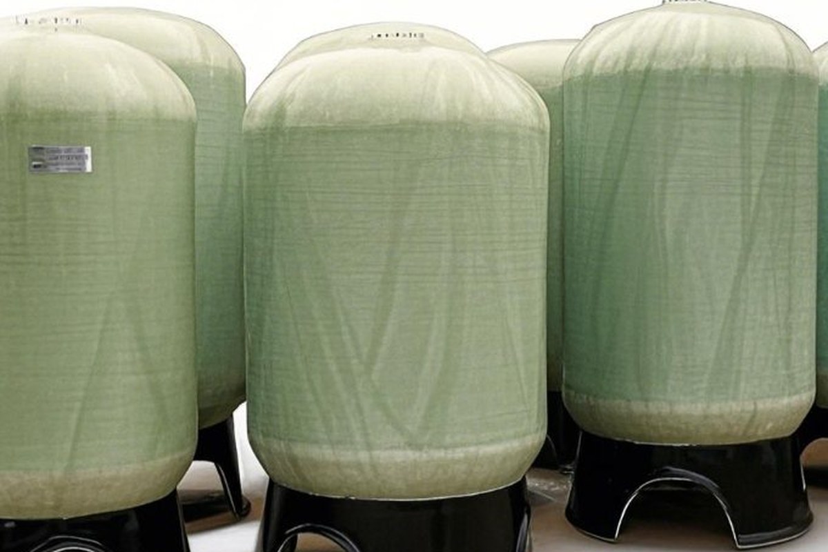
A 12-metre-diameter FRP scrubber or storage tank cannot travel down a road. Above a certain diameter — practically somewhere around 4 to 5 metres of shell diameter, depending on route permits — the vessel has to be delivered as hoop segments, strakes or panels and joined on site. The structural logic then shifts completely: the shell that left the factory was a continuous, factory-cured, factory-tested laminate, and what arrives on site is a set of pieces whose performance now depends entirely on the quality of joints made in the open air by whoever is standing there.
Nothing else in the project carries this risk concentration. A defect in one factory laminate is a manufacturing statistic; a defective field joint is a single-point failure in a shell carrying hydrostatic pressure, chemical content and often wind and seismic load at the same time. This guide covers the four things that decide whether field joints hold: where you place them, how you build them, how you cure them once the sun goes down, and how you prove all three before filling the vessel.
1. When the Vessel Has to Be Segmented, and What Changes
Segmentation is driven by transport, not by design preference. Road and container limits fix the maximum single-piece shell diameter and length; site access, crane capacity, foundation readiness and the length of the shutdown window then decide whether the vessel arrives as two half-shells, as a stack of circumferential rings plus heads, or as flat panels laminated into a shell on site.
What changes when the joint moves from the factory to the field is not the required strength — the joint must still perform as a structural element of the shell — but the controllability of the process around it. Factory lamination runs under a roof, on a rotating mandrel, at a controlled temperature, with resin mixed to a documented catalyst ratio, by laminators whose work is checked against a written procedure and an internal quality plan. Field lamination has weather, wind-blown dust, dew, direct sun, thermal cycling, a cramped working position inside a shell, and a schedule that usually says the vessel must be ready for filling next week.
The response to that is not heroics. It is a written joint procedure, a defined sequence, verifiable hold points, and — most importantly — a cure schedule that is deliberately designed rather than left to ambient luck.
Commercial point worth making to a client before the contract is signed: field-erected FRP vessels are a normal, well-established part of the industry, but they are procurement items, not site improvisation. If the quotation does not include a joint lamination procedure, a cure schedule and a documented acceptance test, the price is not low — the scope is simply missing.
2. Joint Layout: Placement Rules That Decide Stress at the Seam
Where a joint sits determines how hard it has to work, and the standard for contact-moulded corrosion-resistant tanks ties joint requirements directly to the head of liquid above them. In ASTM D4097 the minimum width of a circumferential joint overlay is selected from the product of H (distance from the top of the liquid level down to the joint) and D (tank inside diameter) — in other words, joints low in a tall, wide tank need materially wider overlays than joints near the top of a small one.
Practical layout rules that follow from this:
- Keep circumferential joints as high as the segmentation allows. Every metre of elevation removed from a joint's position reduces the hydrostatic head it carries and therefore the overlay width it needs.
- Do not put a joint on or within the knuckle region. The bottom knuckle is a high-bending-stress zone, and the standard is explicit that a joint near the bottom tangent line is not counted as contributing to knuckle reinforcement. Put the first girth seam above the knuckle and add the knuckle laminate in its own right.
- Axial (vertical) joints carry more load per unit length than circumferential joints. The standard handles this by requiring axial joint overlay widths of twice the tabulated circumferential value for the same H×D; if you can orient the segmentation to minimise vertical seams, do so.
- Stagger seams. Where reinforcement layers overlap, laps in successive layers should be staggered from the laps in the preceding layer — ASTM D4097 specifies at least 2.25 in (67 mm) of stagger. Stacked laps become a thick, resin-rich, crack-prone ridge.
- Move joints clear of nozzles, manways and support saddles. Cut-outs, gussets and saddle contact points generate local stress concentrations; laminating a seam through one creates a defect you cannot inspect.
3. Joint Types: Butt-and-Strap, Flush Tapered and Laminated Lap
Three configurations cover the overwhelming majority of field-erected FRP vessels. They are not interchangeable, and the choice usually runs straight off whether the inside surface must be smooth.
| Joint type | How it is built | Strength and stiffness | Inside surface | Where it fits |
|---|---|---|---|---|
| Butt-and-strap (butt joint with exterior overlay) | Shell edges are brought together, crevices filled with a filled resin paste, then interior and exterior overlays laminated across the seam | Overlay thickness equal to shell thickness; shear is carried through the overlay bond line | An interior overlay leaves a lamination ridge unless it is faired | Liquid-service tanks and vessels where some internal ridge is acceptable; the workhorse configuration |
| Flush / tapered (scarf) joint | Both edges are tapered or one edge is stepped, the joint is made flush by laminating into the taper, then exterior overlay added | High, with a smooth load path and less eccentricity than a butt-and-strap | Smooth; corrosion barrier can run continuously across the seam | Corrosion-critical service, agitated vessels, hygienic or flow-sensitive duty, vessels with internal linings |
| Laminated lap (shingled) joint | One shell section overlaps the next and the overlap is laminated over | Depends entirely on the lap length and the bond quality; eccentric load path | Step on the inside | Access-restricted areas, low-pressure secondary structures, repairs where a taper is impractical |
Two rules apply regardless of type. First, the joint overlay thickness is tied to the parent shell thickness — in ASTM D4097 the structural joint overlay thickness shall be equal to the shell thickness determined for the shell, so a joint cannot be thinner than the wall it joins. Second, the corrosion barrier through the joint is a separate requirement from the structural overlay and is not counted as structural: the standard requires the barrier component of the joint to be formed in the same manner as the inner surface and interior layer, with a minimum overlay width of 4 in (100 mm).
4. Overlay Width and Thickness: Working From the Standard, Not From Habit
Overlay width is the parameter most often set by folklore ("we always use 200 mm") and most often wrong. ASTM D4097 Table 3 gives the minimum width of outside overlay for circumferential joints as a function of H×D, with H the depth of liquid above the joint in feet and D the inside diameter in feet.
| H × D (ft × ft) | 60 | 100 | 140 | 180 | 220 | 260 | 300 | 340 | 380 | 420 | 460 | 500 and above |
|---|---|---|---|---|---|---|---|---|---|---|---|---|
| Minimum circumferential overlay width | 4 in (102 mm) | 4 in (102 mm) | 5 in (127 mm) | 6 in (152 mm) | 7 in (178 mm) | 8 in (203 mm) | 9 in (229 mm) | 10 in (254 mm) | 11 in (279 mm) | 12 in (305 mm) | 13 in (330 mm) | 14 in (356 mm) |
| Same joint, axial (vertical) orientation | Axial joint overlay widths shall be twice the width shown above for the same H × D | |||||||||||
Worked example: a 12 ft (3.66 m) inside-diameter tank jointed 10 ft (3.05 m) below the top of the liquid level gives H×D = 120, which lands between the 100 and 140 columns — take the 140 row, giving a 5 in (127 mm) minimum circumferential overlay. The same seam positioned as a vertical joint needs 10 in (254 mm). This is the arithmetic that converts "we always use 200 mm" into a defensible number, and it also shows why the same 200 mm overlay is generous on one vessel and insufficient on another.
Width alone is not enough. The overlay must also be built to shell thickness, must be centred on the seam, and must taper at its edges so that the load transfer into the parent laminate is gradual rather than ending in a step. A thick-edged overlay terminating abruptly concentrates peel stress exactly where the field joint is weakest.
5. Surface Preparation: The 36-Grit Rule and the Wax Trap
Secondary bonding in FRP is a surface phenomenon. A cured laminate that has been sitting in a factory yard or under a tarpaulin for six weeks has absorbed moisture, accumulated contamination and — if the resin system was formulated with a paraffin wax for ambient cure — carries a waxy film over the entire surface. Resin will not bond reliably to any of it.
The preparation requirements are specific and, unusually for site work, easy to verify:
- Grind with 36 grit or coarser. The requirement is abrasive media of 36 grit or coarser, and the purpose is to expose glass fibre rather than to polish resin. A fine disc that merely scuffs the surface leaves a resin smear that looks prepared and bonds poorly.
- Grind wider than you will laminate. The roughened area must extend beyond the lay-up area so that no reinforcement is ever applied to an unprepared surface — you cannot have an overlay edge landing on smooth, waxed, or glossy resin.
- Remove all wax and release agent. Paraffin wax blooming to the surface is normal in ambient-cure laminates; it must be mechanically removed, not wiped. This is the single most common cause of a field joint delaminating months later.
- Clean, dry, and check the dew point. Surfaces must be clean and dry before lay-up. Laminating over a shell that has been sitting in night air below the dew point traps moisture in the bond line. Measure substrate temperature and dew point and keep a margin of at least 3 °C.
- Work within a temperature window. Ambient-cure polyester and vinyl ester systems behave predictably roughly between 15 °C and 30 °C, with catalyst ratio adjusted for temperature. Below about 15 °C, cure slows dramatically and under-cured joints become the norm unless heat is applied. Above about 32 °C, working time collapses and the risk shifts to exotherm damage and blistering.
- Re-apply paraffinated resin after lay-up. The standard requires the entire roughened area, not just the new laminate, to be coated with paraffinated resin after the joint lay-up is made — this seals the surface, suppresses styrene loss, and prevents an under-cured, tacky open edge.
6. Lamination Sequence and Roller Discipline
Field lamination quality lives or dies on two things: sequence and compaction. Sequence because the corrosion barrier must be continuous and unpunctured; compaction because air and unbonded glass are the seed of every delamination.
A sequence that satisfies both, and that mirrors the standard's requirements for joint construction:
- Fill the crevices first. A highly filled resin paste is worked into the gap between the joined pieces and faired smooth, leaving a flat surface for the first reinforcement. Skipping this creates a resin-starved valley that no overlay can bridge properly.
- Build the interior (corrosion barrier) first. Where the joint is accessible from both sides, the interior overlay is built as a minimum of two plies of 1.5 oz/ft² (0.46 kg/m²) chopped strand mat followed by a resin-rich layer reinforced with surfacing mat — the equivalent of the shell's inner surface and interior layer, with a minimum overlay width of 4 in (100 mm) and centred on the joint. The barrier is not a structural element, so it must not be counted towards joint thickness.
- Then the structural overlays. Alternating chopped-strand mat and woven roving or non-woven biaxial fabric, built to the shell thickness, working outwards so that each successive layer is wider than the last, producing the smooth contoured laminate centred on the joint rather than a stack of equal-width strips.
- Stagger every lap by at least 2.25 in (67 mm). Successive layers' laps must not line up.
- Compact each layer before adding the next. Paddle rollers and consolidation rollers from the centre outwards, working out entrapped air, until the laminate goes translucent and no dry glass shows. Wet-out is judged visually, not by time elapsed.
- Control exotherm on thick builds. A rule of thumb in field practice is to limit any single continuous build-up to roughly 6 mm and let it cool before continuing, particularly in a hot, still shell interior where heat cannot escape. Exotherm peaks high enough to discolour or crack the laminate are a real risk on thick joints in enclosed tanks, and ventilation and shade matter as much as catalyst ratio.
- Hold point before proceeding. Do not laminate the next layer over a joint that has not been visually inspected for dry patches, air entrapment, pinholes, uneven thickness and delaminated edges at overlaps.
7. Post-Cure: Why Field Joints Need Heat, and How to Apply It
Ambient cure does not finish the job. Room-temperature-cured polyester and vinyl ester laminates reach a useful mechanical condition within 24 hours but do not reach the crosslink density they need for full chemical resistance and dimensional stability. Elevated-temperature post-cure completes the reaction, raises the glass transition temperature and heat-distortion temperature, and — critically for field joints — reduces residual internal stress, which is exactly the mechanism behind the delayed cracking and interlayer separation that appears months after commissioning on shells that were never post-cured.
Where service is severe (concentrated acids, oxidising chemicals, solvents, elevated temperature), post-cure is not optional. Published guidance from resin and tank practice indicates the following order of magnitude, which should always be confirmed against the specific resin supplier's data sheet and the corrosion-resistance test recommendations of ASTM C581:
| Resin system | Typical post-cure condition | Notes |
|---|---|---|
| Bisphenol-A epoxy vinyl ester (general chemical service) | Around 24 h at ambient, then approximately 6 h at 80 °C | The widely used reference schedule for a standard bisphenol-A epoxy vinyl ester. Applies to joints as well as the parent shell. |
| Novolac epoxy vinyl ester (solvent and oxidising duty) | Elevated post-cure around 100 °C | Higher temperature to match the resin's higher heat-distortion temperature class |
| General rule for build time | Add roughly 1 h of post-cure per 1 mm of laminate thickness; field schedules commonly land between 5 h and 15 h total | Thick joints need time, not merely temperature, for the core of the laminate to reach the target |
| Service below 100 °C, mild or neutral media | Post-cure beneficial but sometimes omitted; verify by Barcol and a solvent-wipe test | Post-cure remains the reliable route to consistent Barcol hardness and long service life |
Applied to a field joint, the practical sequence is: complete the lamination, allow the resin to cure sufficiently to hold its shape, then heat the joint deliberately.
- Heat the joint, not the air. Infrared lamps, electrical heat blankets or enclosed tents with forced hot air all work. Whatever the method, temperature must be measured with contact thermocouples on the laminate surface and, on thick joints, on the underside and in the bond line region — air temperature inside a tent says very little about a 25 mm laminate.
- Ramp and cool slowly. A ramp of no more than about 10 °C per hour in each direction avoids introducing a new thermal gradient stress into a laminate that is finally releasing its own.
- Never use an open flame. Direct flame heating risks local decomposition, styrene ignition and an uneven cure that produces a joint that tests hard on the outside and remains soft inside.
- Insulate the shell while heating. An FRP shell is an excellent insulator; heat applied outside will not reach the joint bond line without deliberate lagging. Plan the heating setup before the lamination starts, not after.
- Post-cure before hydrotest, always. Filling a tank tests the joint to its maximum sustained stress. Doing so on an under-cured laminate is the classic way to convert a manageable defect into a crack.
8. Verifying Cure and Joint Integrity Before the Tank Sees Liquid
Cure verification in FRP is indirect but reliable if you use more than one method and compare against the parent shell.
- Barcol hardness (ASTM D2583). The standard instrument check on cured FRP. Minimum values for chemical service are commonly quoted in the 35–40 range, and certification schemes such as ASME RTP-1 require cure to be confirmed either at those levels or at not less than 90% of the resin manufacturer's recommended fully cured hardness. Measure in several positions on the joint and in the adjacent parent laminate: a joint reading 10 points below the parent shell means the parent is fine and your field cure is not.
- Solvent wipe sensitivity. A wipe with acetone or styrene on a cured laminate surface that softens or becomes tacky indicates residual unreacted monomer. Quick, cheap and useful as a screen where post-cure was omitted.
- Visual defect classification (ASTM D2563). Standard terminology and classification for visual defects in reinforced plastic laminates — use it to make your inspection findings objective and to grade severity rather than arguing about what looks acceptable.
- Holiday / spark testing (ASTM D5162 and NACE SP0188). High-voltage spark testing or low-voltage wet sponge testing locates pinholes and discontinuities in a corrosion barrier. One important caveat from industry practice: spark testing is appropriate for new laminate on conductive or accessible substrates but is not recommended on used FRP linings, where chemical permeation can raise conductivity and cause burn-through. Select voltage by laminate thickness.
- Glass content and laminate properties (ASTM D2584, D638, D790). For a critical vessel, a cut test coupon from a sacrificial extension of the joint laminate gives glass content, tensile and flexural strength, and lets the client verify the joint against the shell's specified values rather than trusting a visual pass.
- Dimensional check. Out-of-roundness and distortion matter because a distorted shell loads its foundation and nozzles unevenly. ASTM D4097 tolerances on inside diameter (around ±1%, including out-of-roundness) are a useful benchmark even where the vessel is designed to another standard.
9. Hydrotest and Acoustic Emission Acceptance
The final proof of a field-erected vessel is filling it. Two acceptance routes are in common use, and the better projects do both.
Hydrostatic leak and strength test. In the ASME RTP-1 framework, hydrostatic testing is specified at typically 1.5 times the maximum allowable working pressure held for 30 minutes, or — for atmospheric tanks — a standing fill. Fill in stages (commonly 50%, 75%, and then full) with holds between stages, inspecting every seam, nozzle and support for weeping, blush, whitening or cracking, and monitoring foundation settlement and shell deflection as the liquid load goes on. Keep records of fill level against time; a joint that only weeps when the shell is above 80% full tells you the defect is in the lower barrel, not at the top.
Acoustic emission examination (ASTM E1067/E1067M). The practice covers sensor-based monitoring of FRP tanks and vessels under pressure or vacuum to determine structural integrity, and it detects exactly the failure modes a field joint is prone to: resin cracking, fibre debonding, fibre pullout, fibre breakage, delamination, and bond failure in assembled joints such as nozzles and manways. Its scope is bounded — it applies to vessels operating at internal pressures up to about 1.73 MPa (250 psia) above static and to vacuum service down to about 0.10 MPa differential, and to laminates with glass content above 15% by weight — which covers most chemical-service FRP equipment.
Two features make AE especially useful for segmented vessels. It is performed during the fill itself, with the vessel progressively loaded through defined increments (typically 50%, 75%, 87% and then 100% of capacity) so defects announce themselves as stress is applied. And because composites do not obey the Kaiser principle the way steel does, the Felicity ratio becomes the diagnostic: acoustic activity reappearing at a lower load than previously reached indicates active damage propagation, with a Felicity ratio below 1 being the accepted warning sign. That is a far more actionable result than "no leak at test pressure".
10. Field Quality System: Hold Points, Evidence and Common Failures
Everything above collapses into a short inspection and test plan. The point of writing it down is not administration: it is that each hold point catches a specific failure mode while it is still cheap to fix.
| Hold point | Verification | Evidence to keep | Failure it prevents |
|---|---|---|---|
| Before grinding | Joint layout dimension check; seam positions vs drawing; local weather (ambient and substrate temperature, dew point) | Dimensional record, weather log with times | Joint in the knuckle region; laminating on damp substrate |
| Surface preparation sign-off | 36-grit or coarser abrasive used; roughened area extends beyond lay-up; wax and contamination removed; glass exposed, not resin-smeared | Photographs plus inspector signature | Delamination at the bond line months later — the single most common field joint failure |
| Barrier and first structural layer | Interior overlay width at least 100 mm, two plies of 0.46 kg/m² CSM plus surfacing mat; crevice paste faired; no dry glass | Layer-by-layer record with resin batch and catalyst ratio | Resin-starved barrier, chemical attack path through the seam |
| Overlay width and thickness | Measured width against the H×D table (doubled for axial joints); thickness built to shell thickness; laps staggered at least 67 mm | Dimension sheet with joint elevations | Under-strength joint; stacked lap ridge cracking |
| Cure check | Barcol readings on joint and parent laminate; post-cure temperature and time record from contact thermocouples | Cure log with ramp profile | Under-cured joint failing or cracking in service |
| Pre-fill inspection | Visual defect classification per ASTM D2563; holiday/spark test on accessible new laminate; nozzle and gusset inspection | Defect register with disposition | Pinholes, unbonded edges and nozzle tie-in leaks reaching hydrotest |
| Hydrotest / AE | Staged fill with holds; leak and deflection monitoring; AE zoning and Felicity ratio interpretation where specified | Fill curve, AE report, settlement readings | Commissioning leak; undetected damage propagation |
Against that plan, the failures we see repeatedly on site are predictable: paraffin wax left on the bond surface; grinding done to a smooth finish with a fine disc so that no glass is exposed; an overlay built to familiar width rather than to the head-and-diameter requirement; laminating in the evening and filling in the morning with no post-cure; exotherm damage on a thick joint in a closed, unshaded shell; and temporary bracing removed before the joints have cured, letting the shell relax out of round and load the seams in a way the design never anticipated.
Henan HuanGang fabricates FRP storage tanks, vessels, scrubbers and ductwork either shop-complete or in transportable sections, and supplies each field-erected vessel with a joint lamination procedure, the H×D overlay width calculation for the actual joint elevations, a post-cure schedule keyed to the resin system quoted, and an inspection and test plan aligned with ASTM D2583, D2563, D2584, D4097 and E1067. Send us the vessel geometry, service medium, design temperature and site access constraints, and we will confirm the segmentation plan, joint configuration and cure schedule before the vessel is built. Related reading: FRP storage tank transport and installation, tank nozzle, manway and bolt torque design, gel coat and corrosion barrier liner design and filament winding angle design for pressure pipes and tanks.
Need help selecting FRP products?
Our engineers answer technical questions free of charge.
Ask an Engineer on WhatsApp