
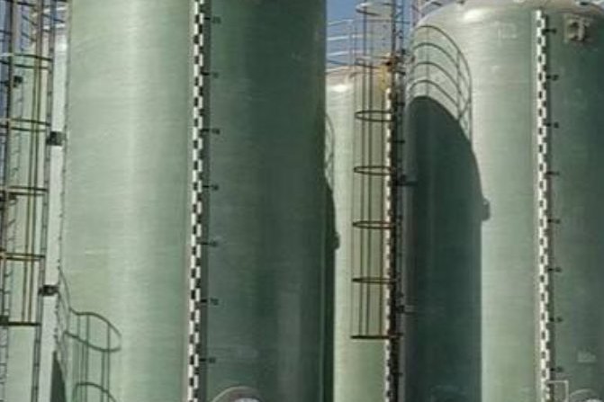
Two FRP tanks can look identical on a drawing and carry a tenfold difference in engineering cost. The difference is not the laminate drawing, the resin datasheet or the nozzle schedule: it is the code path behind them. A 12 m³ vertical tank built to an ASTM specification and the same tank built to ASME RTP-1 have different design reports, different quality records, different inspection intensity and different prices — and in most projects the buyer never states which one is being quoted, so the comparison is meaningless.
This guide is written for the engineer or buyer specifying corrosion-resistant FRP tanks, vessels and column shells. It sets out the scope boundaries between ASME Section X, ASME RTP-1 and the ASTM tank standards, what the Section X classes actually require of a fabricator, the numerical design rules inside RTP-1, the documentation package that proves compliance, and the specification wording that stops a project drifting onto the cheapest interpretation of the word “ASME”.
The engineering arithmetic below uses the design factors and strain limits from the standards themselves. Where a value is a common industry practice rather than a published requirement, it is labelled as such.
1. Start With the Pressure, Because the Pressure Chooses the Code
The first decision in FRP equipment procurement is not the resin, the diameter or the corrosion barrier. It is whether the vessel sits inside or outside the pressure scope of the two ASME documents that apply to reinforced thermoset plastic equipment.
- ASME BPVC Section X — Fiber-Reinforced Plastic Pressure Vessels. Its pressure scope begins at 15 psig internal and extends upward, the upper limit depending on the size and construction of the vessel. It also covers vessels subject to external pressure from 0 to 15 psig.
- ASME RTP-1 — Reinforced Thermoset Plastic Corrosion-Resistant Equipment. Its scope is stationary vessels used for storage, accumulation or processing of corrosive or other substances at pressures not exceeding 15 psig internal and/or external, above any hydrostatic head.
Those two sentences decide which document governs most chemical storage and process equipment, and the boundary is crossed surprisingly easily. A vertical tank holding fluid of specific gravity 1.35 to a 6 m depth develops a design pressure of 79.5 kPa, or 11.5 psig — comfortably inside RTP-1. Raise the fluid to specific gravity 1.84 at the same depth and the pressure is 108.3 kPa, or 15.7 psig, which is past the boundary and into Section X. Add four metres of depth to the first case and the same 1.35 specific gravity fluid produces 132 kPa, or 19.2 psig — again Section X. Nobody changed the tank drawing. The code changed.
| Design pressure on the shell | Typical process case | Governing document | What the document adds |
|---|---|---|---|
| Atmospheric, within ±14 in. w.c. | Vented chemical storage, water and effluent tanks, contact-moulded or filament-wound shells | ASTM D3299 (filament wound) or ASTM D4097 (contact moulded) | Materials, design, dimensions, tolerances, workmanship and appearance. No fabricator quality-system certification is enforced. |
| 0 to 15 psig internal or external, above hydrostatic head | Corrosive storage and process vessels, scrubber shells, reactor bodies, semiconductor process tanks | ASME RTP-1 | Mandatory user requirement specification, certified design report, laminate qualification, fabrication quality programme, inspection and ASME certification mark. Voluntary in law. |
| 15 psig internal and above | Pressure vessels, pressurised process equipment, higher-head storage | ASME BPVC Section X, Class I, II or III | Code construction with a manufacturer's design report, class-specific design qualification, production testing and inspection by an authorised inspector. Enacted into law in 37 jurisdictions in the United States and Canada. |
| Europe, tanks and vessels above ground | Projects specifying European practice instead of ASME | EN 13121-3, or BS 4994 where an older UK specification is inherited | Design by rules with a minimum overall design factor; EN 13121-3 uses a Kmin of 6 or 8 for basic design, BS 4994 a minimum K of 8. |
| Filament-wound pressure vessels, below 20 MPa, −30 °C to 120 °C | European pressure-vessel scope equivalent to Section X | BS EN 13923 | Materials, design, manufacture and testing requirements for filament-wound FRP pressure vessels. |
One more scope boundary matters and is frequently missed: reinforcement type. RTP-1 governs vessels reinforced with glass fibre. Section X also addresses vessels reinforced with carbon and aramid fibre. If the design calls for a hybrid or high-modulus reinforcement, the European and ASTM documents in the table fall away.
2. Section X Class I: Qualification by Destroying a Prototype
Section X was first published in 1974 and took the conservative route that pressure-vessel codes usually take for unfamiliar materials: prove the design and the fabrication procedure by building a vessel exactly as the production vessel will be built, and pressurise it until it fails. Class I is that route. It, and Class III, qualify by the destructive test of a prototype. Class II, discussed in the next section, is the rules-based alternative added later.
What Class I actually imposes on a project is procedural, and it is worth stating plainly to anyone who has not bought code equipment before:
- The design is not qualified by calculation alone. The prototype test is the qualification. That makes the first article expensive and means the design cannot be revised after the test without re-qualification — the code requires a qualified procedure, and deviations from that procedure require re-qualification.
- Fabrication is constrained to defined processes. Vessel fabrication under Section X is limited to bag moulding, centrifugal casting, filament winding and contact moulding. A process outside that list is not a Section X vessel, whatever the laminate test data shows.
- Certain services are excluded outright. Vessels built to Section X are not permitted to store, handle or process lethal fluids. That is a code-level exclusion, not a design margin, and it cannot be engineered around.
- Metallic components follow Section VIII Division 1. Flanges, nozzles, internal metallic parts and appurtenances that form part of the FRP vessel are designed and constructed to the metal pressure-vessel rules, not to the composite rules.
The economic consequence is the same one that drove the industry to develop the ASTM tank standards in the first place. A one-off atmospheric storage tank built by destroying an identical prototype is not an economical proposition; that is exactly why ASTM D3299 and D4097 were issued for tank work in 1974 and 1982, and why RTP-1 followed in 1989. Section X exists for the pressure cases where the prototype cost is justified by the duty.
3. Section X Class II: Mandatory Design Rules Plus NDE Acceptance
In 1989 the Section X committee revised the section to allow FRP pressure vessels without the destructive prototype test. Class II is that route, and it trades a destroyed vessel for three things: strict design rules, fabrication quality requirements, and acceptance testing by non-destructive examination. In particular, acoustic emission testing during the proof test is the method that allows a Class II vessel to be accepted without cutting it open.
In practice, the Class II path is the one most non-specialist buyers should expect when they ask for a “Section X vessel”, and the deliverables are documentation-heavy rather than test-heavy:
- Mandatory design procedures. The shell, heads and nozzle reinforcement are designed to the section's rules, with laminate properties established from test panels of the same construction and cure as the production laminate — tensile and flexural data to ASTM D638 and D790, fibre content to ASTM D2584, and thickness measurement. A design report is produced and certified.
- Acceptance by NDE rather than by destruction. Acoustic emission monitoring during proof pressurisation, visual examination to defined acceptance criteria, cure verification by Barcol hardness to ASTM D2583, and thickness verification. ASTM E1067 is the practice that covers acoustic emission examination of FRP tanks and vessels, and it is the method to name in a specification: the test detects and locates active defects such as delamination, debond and fibre fracture that grow under load.
- Production discipline. Qualified procedures, controlled material traceability and inspection by an authorised inspector are conditions of applying the code mark, not optional services.
- Class III covers the constructions that do not fit the first two. Hybrid and advanced composite designs, including fully wrapped constructions with non-load-sharing liners, also qualify through prototype destructive testing.
The distinction between the classes should appear on the purchase order, not be discovered in the design review. “ASME Section X” is not a specification: Class I, Class II or Class III, with the design report and the acceptance test named, is.
4. ASME RTP-1: What the Corrosion-Equipment Programme Requires
RTP-1 is a certification programme as much as a design standard. It was issued in 1989, grew out of an industry quality-assurance report written because the ASTM tank standards specify technical requirements but do not enforce a fabricator quality system, and it applies to stationary vessels at pressures up to 15 psig. Unlike Section X, it has not been enacted into law anywhere; it is a voluntary standard that owners and engineering contractors specify contractually. That is not a weakness in service — it is simply why the specification must name it explicitly.
The programme has four moving parts that a buyer should understand before evaluating quotations:
- The user writes the requirement. RTP-1 places the design conditions, material selection and service limitations in a User's Basic Requirements Specification supplied by the purchaser, covering the design pressure and temperature, the chemical service including concentration and any trace constituents, the specific gravity and maximum liquid level, external loads, and any critical-service classification.
- The fabricator writes and certifies the design report. The manufacturer's design report is prepared by the fabricator and certified by a qualified designer. Design can follow Subpart 3A, design by rules, or Subpart 3B, design by stress analysis using classical laminate theory or finite element analysis. Rules-based design is faster and cheaper; analysis-based design is what makes non-standard geometry, large nozzle openings and unusual support conditions tractable.
- The laminate is standardised and tested. RTP-1 defines standard laminate types with declared minimum properties, so the designer starts from a qualified construction rather than a supplier claim.
- The shop is qualified, not just the vessel. The fabricator must hold the ASME certification with the RTP designator, operate an approved quality-control programme, and demonstrate capability through the shop qualification requirements of the standard, including the manufacture and testing of a demonstration laminate and a demonstration vessel. Each vessel is documented with a manufacturer's data report signed by the certified individual and the inspector, and RTP vessels can be registered by filing that report with the National Board of Boiler and Pressure Vessel Inspectors.
5. The Numbers Inside RTP-1
This is where RTP-1 differs most sharply from a typical corrosion-barrier specification written in-house, and where a buyer can lose a lot of money by not reading it.
| Requirement | Value | What it means commercially |
|---|---|---|
| Design factor, sustained loads | 10 | Allowable stress is one tenth of the ultimate laminate strength. This single number drives more wall thickness than any other input. |
| Design factor, intermittent loads | 5 | Wind, seismic and similar transient loads may use a less severe factor. The two cases must be combined correctly, not mixed. |
| Corrosion barrier strain limit, sustained | 0.13% for resins with elongation at break of 4% or more; 0.10% otherwise | A barrier limit, not a structural limit. It exists to keep the corrosion barrier crack-free for the design life. Behind it sits a resin selection decision. |
| Corrosion barrier strain limit, intermittent | 0.20% | Applies to the transient load case. |
| Minimum overall laminate thickness | 0.22 in (5.59 mm) | A floor on the design, independent of pressure. It governs small-diameter vessels, where the pressure calculation alone would produce a thinner wall. |
| Corrosion liner minimum thickness | 100 mil (2.54 mm) | Typically two layers of C-glass surfacing veil with chopped strand mat in a corrosion-grade resin system. |
| Resin heat deflection temperature | 180 °F (82 °C) minimum | Sets the service-temperature ceiling of the standard construction. Higher-temperature duties require a different resin system and separate qualification. |
| Reinforcement | E-glass or E-CR glass; balsa core permitted in structural laminates | Rules out carbon and aramid reinforcement — that is Section X territory. |
| Cure verification | Barcol hardness to ASTM D2583, commonly a minimum of 35–40 or 90% of the resin manufacturer's recommended value | A production control test that catches under-cured laminate before the vessel ships. |
| Leak test | Commonly 1.5 × MAWP held for 30 minutes; atmospheric tanks longer, up to 24 hours, depending on design and service classification | Specify the test pressure, hold time and documentation explicitly rather than accepting “hydrotested”. |
| Chemical resistance data | Immersion testing to ASTM C581, with retained properties reported over time; the standard's own chemical resistance appendices for resin selection | Chemical resistance is a qualification activity, not a claim. Budget time for it when the medium is not in the published tables. |
The standard also defines standard laminate types so that design and testing have a common starting point. The declared minimum values are the ones a designer may use without further testing:
| Laminate type | Construction | Typical thickness range | Minimum tensile strength | Minimum flexural strength |
|---|---|---|---|---|
| Type I | Surfacing veil plus all chopped strand mat | 0.18–0.74 in (4.6–18.8 mm) | 9,000 psi (62 MPa) | 16,000 psi (110 MPa) |
| Type II | Surfacing veil plus alternating chopped strand mat and woven roving | 0.22–0.76 in (5.6–19.3 mm) | 12,000–15,000 psi (83–103 MPa) | 19,000–22,000 psi (131–152 MPa) |
| Type X | Determined by laminate analysis rather than by the standard types | Non-standard | By calculation or test | By calculation or test |
A request for quotation that says “FRP tank, 12 m³, HCl 32%, design 15 psig” can be answered three legitimate ways — Type I rules design, Type II rules design, or Type X analysis — with three different wall thicknesses and three different prices. Naming the laminate type and the design method in the enquiry is the cheapest engineering work a buyer will ever do.
6. Working the Design Factor: What DF 10 Actually Does to a Wall
The most common misunderstanding in FRP vessel procurement is that the design factor is a safety margin “on top of” the corrosion barrier allowance. It is not: it applies to the structural laminate, and its result is a working strain that has to sit inside the barrier limits. The arithmetic below uses the thin-shell hoop equation t = pD / (2σallow) as an order-of-magnitude check to show the effect of the factor. A code design follows the standard's own laminate unit-strength rules, not this simplification, but the ranking of the variables is identical.
Take a shell at 79.5 kPa (11.5 psig) — the six-metre, specific gravity 1.35 case from section 1 that sits inside the RTP-1 pressure scope.
| Shell diameter | Design basis | Allowable stress | Required thickness | Working strain at allowable stress |
|---|---|---|---|---|
| 3000 mm | Type II laminate, design factor 10 | 8.30 MPa | 14.4 mm | 0.098% |
| 3000 mm | Type I laminate, design factor 10 | 6.20 MPa | 19.2 mm | 0.073% |
| 3000 mm | Type II laminate, design factor 5 (intermittent case) | 16.60 MPa | 7.2 mm | 0.195% |
| 3600 mm | Type II laminate, design factor 10 | 8.30 MPa | 17.2 mm | 0.098% |
| 3600 mm | Type I laminate, design factor 10 | 6.20 MPa | 23.1 mm | 0.073% |
| 3600 mm | Type II laminate, design factor 5 (intermittent case) | 16.60 MPa | 8.6 mm | 0.195% |
Assumptions: laminate ultimate tensile strength taken as the declared minimum for each type (62 MPa for Type I, 83 MPa for Type II), tensile modulus 8500 MPa for the working-strain column.
Three things fall out of this table, and they explain most of the price difference between “over-designed” and “thin” quotations:
- The design factor of 10, not the pressure, sets the wall. Halving the factor from 10 to 5 halves the required thickness. Any quotation that is dramatically cheaper for the same duty is using a different factor, a different laminate type, or both — which is legitimate only if the intermittent-load case is what is being designed, and illegitimate if it has quietly replaced the sustained case.
- The DF-10 stress check and the barrier strain limits are closely related, not independent. At the declared minimum for Type II laminate, the DF-10 allowable of 8.30 MPa corresponds to a working strain of 0.098%, which sits just under the 0.13% sustained barrier limit. With a resin whose elongation at break is below 4%, the barrier limit tightens to 0.10% — equivalent to 8.50 MPa at the same modulus. The two criteria become effectively co-governing, which is a strong argument for choosing a resin system with adequate elongation rather than specifying the cheapest corrosion-grade resin.
- The minimum laminate thickness governs small vessels. A 1200 mm diameter tank at the same pressure would calculate well below 5.59 mm, and the code minimum then decides the wall. Buyers who negotiate on the calculated thickness alone are negotiating on a number that was never the governing one.
The equivalent European check behaves differently. BS 4994 uses an overall design factor built from multipliers — K = 3 · k1 · k2 · k3 · k4 · k5 — covering manufacturing method, chemical environment, heat deflection temperature, cycling and cure. A machine-wound, thermoplastic-lined vessel with factory post-cure and no significant cycling lands at K ≈ 7.4; the same vessel in an aggressive chemical environment with thermal cycling and no full post-cure reaches K ≈ 25.3. The minimum overall factor in BS 4994 is 8, and EN 13121-3 uses a minimum of 6 or 8 for basic design. Two European quotations on the same tank can differ by a factor of three in wall thickness purely from the k-factors — so the design factor table, not the wall thickness, is the thing to compare.
7. Class I, Class II, RTP-1 and ASTM: The Side-by-Side View
| Feature | Section X Class I | Section X Class II | ASME RTP-1 | ASTM D3299 / D4097 |
|---|---|---|---|---|
| Pressure scope | 15 psig internal and above | 15 psig internal and above | 0 to 15 psig internal and/or external | Atmospheric, within ±14 in. w.c. |
| Design qualification | Prototype tested to destruction | Mandatory design rules plus NDE acceptance testing | Design by rules (Subpart 3A) or by stress analysis (Subpart 3B), certified design report | Design to the specification's own rules; no certified design report |
| Acceptance testing | Prototype burst test on the qualified procedure | Proof test with acoustic emission monitoring, visual and cure checks | Visual acceptance criteria, Barcol cure verification, thickness, hydrostatic leak test; acoustic emission where specified | Material and workmanship requirements, dimensions and tolerances, appearance; testing as agreed |
| Fabricator quality system | Code quality programme with authorised inspection, mark applied | Code quality programme with authorised inspection, mark applied | ASME certification with RTP designator, approved QC programme, demonstration laminate and demonstration vessel | Not a certification programme — supplier quality systems are contractual, not accredited |
| Legal status | Enacted into law in 37 United States and Canadian jurisdictions | Same as Class I | Not enacted into law anywhere; enforced by contract specification | Voluntary industry specification |
| Best fit | Repeat production of a pressure duty where the prototype cost is amortised | Pressure duty without the cost and lost time of a destroyed prototype | Chemical-service tanks and process vessels up to 15 psig where documentation and third-party quality control are required | Atmospheric tanks where the technical requirements are sufficient and accreditation is not required |
Read the table as a cost ladder rather than a quality ladder. Each step down adds project cost and administrative effort; the question is whether the duty requires the step. For a 40 m³ atmospheric effluent tank in a chemical plant, ASTM D3299 with a well-written specification and a fabricator inspection programme may be entirely appropriate. For a 12 m³ reactor shell handling hot hydrochloric acid with a defined design pressure, the documentation and quality-system enforcement in the ASME paths are what the duty is paying for.
8. Documentation: What to Require and How to Check It
Because the difference between the code paths lives in paper, the paper is the deliverable. A specification should require all of the following, and a buyer should expect any of these to be missing if the quotation was priced on a lower path.
| Document | Applies to | What it proves |
|---|---|---|
| User's Basic Requirements Specification (UBRS) | RTP-1 | That the purchaser defined pressure, temperature, chemical service, specific gravity, liquid level, external loads and critical-service classification |
| Manufacturer's design report | Section X, RTP-1 | Design basis, laminate schedule, calculated thicknesses, load cases, certification by the qualified designer |
| Laminate qualification data | Section X, RTP-1 | Tensile and flexural properties (ASTM D638, D790), fibre content (ASTM D2584), thickness measurement on the production construction |
| Chemical resistance data | RTP-1, generally good practice | Retained properties after immersion to ASTM C581 in the actual service medium, at service concentration and temperature |
| Acoustic emission test record | Section X Class II; RTP-1 where critical service is specified | Absence of actively growing defects at proof pressure, with source location; ASTM E1067 covers the practice |
| Barcol hardness record | Section X, RTP-1 | That the laminate met the cure criterion, measured to ASTM D2583 |
| Hydrostatic or pneumatic test record | All paths | Test medium, pressure, hold time, ambient conditions and result |
| Manufacturer's data report and the certification mark | Section X, RTP-1 | That the vessel was built by a certified fabricator under the accredited programme; RTP data reports can be registered with the National Board |
| Fabricator certificate status | Section X, RTP-1 | Verifiable independently: ASME publishes a certificate holder search for accredited companies, and the certificate scope states what the shop is accredited to build |
Verifying the fabricator's certificate status before the purchase order is issued takes a few minutes and is the single highest-value check in the whole procurement. A quotation that offers an ASME-marked vessel from a shop that does not hold the certificate is not a cheap vessel; it is a vessel with no valid mark, and no amount of laminate testing substitutes for it.
9. Cost, Lead Time and the Supply-Chain Reality
Three commercial facts should be built into the schedule, whichever path is chosen:
- RTP-1 accreditation is a shop-level asset, and it is scarce. It requires an approved quality-control manual, ASME audit surveys, qualified personnel and a demonstration vessel. Industry guidance for a mid-sized fabricator setting up the programme puts the implementation at roughly six to nine months, and relatively few fabricators in North America hold it. Lead time and price both reflect this, and there is no way to compress it by negotiating.
- Section X Class I has the cost of a destroyed vessel inside it. The prototype test is the qualification, so the first vessel is partly an engineering expense rather than a deliverable. Where the same design will be produced repeatedly, the cost amortises well. For a single vessel, it rarely does.
- The ASTM path saves money and moves the quality burden to the specification. Because ASTM D3299 and D4097 do not enforce a fabricator quality programme, buying to them means the purchaser carries the inspection and verification work. That is a legitimate choice for atmospheric tanks and a poor one for high-consequence chemical service.
For Chinese and other Asian supply chains the practical implication is worth stating plainly: accredited code fabrication is a capability question, not a price question. A buyer with a code-stamped requirement should confirm certificate status first and negotiate second. A buyer with an atmospheric tank requirement should specify the ASTM standard, the laminate construction, the chemical resistance testing, the inspection plan and the documentation — and will find that a well-specified non-accredited vessel outperforms a badly specified one every time.
10. Specification Wording That Prevents the Usual Arguments
Most disputes in FRP vessel procurement trace back to a specification that named a standard without naming the deliverables. These are the clauses that close the gap. Adapt the wording to your project, but keep every element:
- Name the document, the edition and the class. “ASME BPVC Section X, Class II, 2025 edition” or “ASME RTP-1, current edition, design by the rules of Subpart 3A”. Not “ASME compliant”.
- State the design conditions in the enquiry. Design pressure and vacuum, design temperature and any excursion, chemical service with concentration and trace constituents, specific gravity, maximum liquid level, external loads (wind, seismic, snow, agitation, piping reactions), and the design life.
- Name the laminate type and the acceptance test. “Type II laminate” or “Type X by analysis”, with acoustic emission examination to ASTM E1067 during the proof test where the class requires it.
- List the documentation as a deliverable. Attach the table in section 8 to the purchase order and make submission of the records a condition of dispatch, not a post-delivery service.
- Require the fabricator to declare what it is offering. Design basis, laminate schedule, resin system with heat deflection temperature, corrosion barrier construction, minimum thicknesses, test pressures and the certification status of the shop. A supplier who cannot state these numbers in the offer is not building to a code.
- Keep the scope boundaries visible. Where part of the equipment is piping, ducts or an atmospheric tank, say so and give each item its own standard. A project that calls every composite item “ASME vessel” will end up with mismatched documentation that satisfies nobody.
11. Six Compliance Mistakes That Recur
| Mistake | Consequence | Prevention |
|---|---|---|
| Specifying “ASME vessel” without the section and class | Three fabricators quote three different code paths; the cheapest wins on price and loses on compliance | Name the document, edition and class, and require the design report to state it |
| Assuming RTP-1 covers pressure above 15 psig | The design basis is outside the standard's scope; the certification mark cannot legitimately be applied | Compute the design pressure including hydrostatic head at the maximum specific gravity and go to Section X when it exceeds 15 psig |
| Treating the design factor as a margin on the corrosion barrier | Wall thickness and barrier design get confused; the barrier is left as the thinnest buildable layer | Design the structural laminate to the factor and check the barrier against its own strain limits |
| Requesting a code stamp from a shop without the certificate | No valid mark, and often no genuine third-party inspection; the entire compliance argument collapses at handover | Verify the certificate holder status and the scope of accreditation before ordering |
| Accepting ASTM D3299 for pressure service | Its scope is atmospheric, within ±14 in. w.c., above-ground vertical installation; pressure and vacuum duties are excluded apart from what it classifies | Match the standard to the actual pressure and vacuum case, and treat services above the flash point as excluded unless the standard says otherwise |
| Skipping chemical resistance qualification for an unusual medium | Corrosion barrier performance becomes an assumption; failure shows up as blistering and fibre exposure, not as a burst | Require ASTM C581 immersion data at the service concentration and temperature, and use the standard's chemical resistance data as a screening tool only |
FRP Tanks and Vessels Built to the Design Basis Your Project Names
We fabricate filament-wound and contact-moulded FRP tanks, vessels and column shells in vinyl ester, isophthalic and speciality resin systems, with corrosion barriers built to the laminate and strain requirements your specification names — RTP-1 rules-based design, Section X documentation sets, ASTM D3299 and D4097 tank construction, or European design factors. Our filament-wound FRP chemical storage tanks cover HCl and mixed acid storage, and the horizontal FRP storage tank range covers larger volume and low-headroom installations. For vessel shells that connect to a pipe system, the filament-wound FRP process pipe range is built on the same laminate discipline. Send us the design conditions, the required design basis and the documentation package, and we will confirm the laminate schedule, the corrosion barrier build, the test plan and the records we will issue with the vessel.
Related reading: gel coat and corrosion barrier liner design for FRP tanks · FRP tank and vessel field erection: joint lamination and on-site post-cure · FRP resin selection: vinyl ester versus isophthalic and orthophthalic polyester · FRP tank nozzle and manway design: reinforcement, gaskets and bolt torque · dual-laminate FRP equipment: PP, PVC and PVDF liners
Need help selecting FRP products?
Our engineers answer technical questions free of charge.
Ask an Engineer on WhatsApp