
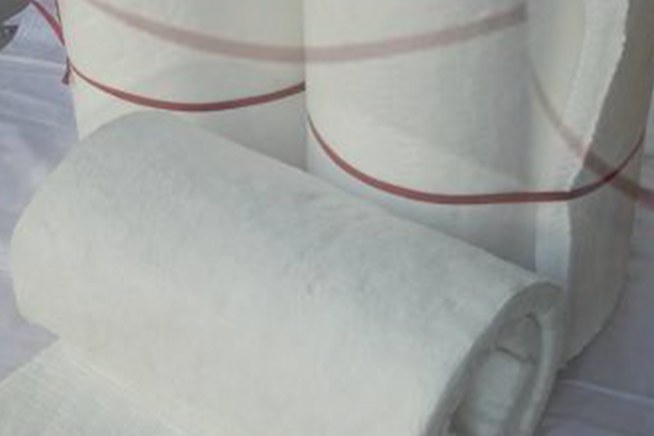
A ceramic fiber module is a stack of folded blanket, compressed and banded so that when the bands are released the fibre expands outward and presses itself against its neighbours and against the furnace shell. That single mechanical idea is what makes modules fast to install and forgiving of thermal movement - and it is also what makes them fail when the compression allowance, the anchor alloy or the expansion joints are chosen carelessly.
This guide treats module linings as an installation problem rather than a materials comparison. If you are still choosing between blanket, board and module as a form, our blanket vs board vs module comparison covers that decision; the wider material logic, including when ceramic fiber is the wrong answer altogether, is set out in our refractory materials selection guide.
1. What a Ceramic Fiber Module Is - and What It Is Not
Module linings are a hot-face insulation system, not a structural refractory. The fibre carries no load, resists no abrasion beyond its coating, and is not a gas seal on its own. What it does well is hold heat in: a 250 mm module lining on a carbon steel shell can keep the shell below 150 °C with a hot face at 1,000 °C, which is why modules dominate furnace roofs, doors and the upper walls of reheat and heat-treatment furnaces.
Three limits define where modules should not be used:
- Gas velocity above roughly 25 m/s on the hot face, unless the surface is hardened and the design has been validated. Above that, erosion of the fibre is rapid and predictable.
- Molten metal or slag contact. Modules are not a containment material.
- Heavy mechanical abuse - charge impact zones, walking surfaces, and any area where the lining is struck during maintenance.
A module lining fails at its anchors and its joints long before the fibre itself is consumed. Design the attachment, then choose the fibre.
2. Module Construction Types Compared
| Type | How it is made | Best suited to | Limitations |
|---|---|---|---|
| Folded (accordion) blanket module | Blanket folded back and forth, compressed and banded, with an anchor tube through the centre | Furnace walls and roofs, curved shells, large areas; lowest cost per m² | Lower hot-face density; needs a hardening coat where gas velocity is high |
| Laminated (layered) module | Blanket cut into strips and stacked with the fibres perpendicular to the hot face | High-velocity zones, burner surrounds, areas needing a denser hot face | More labour per m²; higher cost |
| Vacuum-formed module | Wet-formed fibre shell bonded to a blanket back-up | Where a rigid, abrasion-resistant hot face and precise dimensions are required | Heaviest option; joints must still be packed |
| Hybrid module with board hot face | Ceramic fiber board on the hot side, blanket module behind | Furnaces with moderate erosion, burner blocks, door edges | Board-to-module interface needs careful jointing |
For most reheat furnace roofs and walls, folded modules at 128 kg/m³ or 160 kg/m³ nominal density are the default. Where the flue gas carries dust or burner flames impinge on the lining, a laminated or board-faced module is worth the extra cost.
3. Anchoring Systems: Alloys, Geometry and Temperature Limits
The anchor is the only component that has to survive both the furnace temperature and the mechanical load of the compressed fibre. Alloy selection is driven by the hot-face temperature at the anchor location, which is not the furnace set point - it is the temperature of the fibre immediately around the anchor, typically 100-200 °C lower than the hot face but rising as the lining ages and shrinks.
| Anchor material | Practical continuous limit | Notes |
|---|---|---|
| Carbon steel stud | about 400 °C | Acceptable only behind a thick back-up layer, for example in low-temperature ovens |
| 304 stainless steel | about 800-870 °C | Common default for moderate-temperature furnaces |
| 316 stainless steel | about 850 °C | Better in mildly corrosive atmospheres; similar ceiling to 304 |
| 310 stainless steel | about 1,050 °C | Standard choice for ceramic fiber modules in high-temperature furnaces |
| Inconel 601 / 253MA | about 1,150-1,200 °C | For the hottest roofs and burner zones; significantly higher cost |
| Alumina ceramic anchor | 1,300 °C and above | Used with ceramic cups; brittle, so handle and weld with care |
Geometry matters as much as alloy. Studs are normally 6, 8 or 10 mm diameter, welded to the shell, with a length that suits the module thickness - the stud must engage the full compressed depth, not just the cold end. Spacing follows the module size: a 300 mm by 300 mm module takes one central anchor, which is why spacing of 250-300 mm centres is the practical norm.
Two details are frequently overlooked. First, the ceramic cup or washer that holds the module against the shell must be able to move slightly as the fibre shrinks; a rigidly clamped module tears at the anchor. Second, stainless steel studs welded to a carbon steel shell form a galvanic couple only when moisture is present, so condensation during the first heat-up should be avoided by a slow, staged schedule, as set out in Section 7.
4. Compression and Expansion: The Two Allowances That Decide Lining Life
Ceramic fiber shrinks permanently at temperature. Typical linear shrinkage is 2-3.5 % after 24 hours at 1,260 °C and 3-4 % at 1,400 °C, measured in the manner of ASTM C356. A module installation absorbs that shrinkage by pre-compressing the fibre.
Compression is expressed against the nominal module thickness:
Compression % = (nominal thickness - installed cavity depth) / nominal thickness × 100
- Walls: 10-15 % compression, so a 250 mm module is installed into a cavity of about 215-225 mm.
- Roofs and arches: 15-20 %. Gravity and shrinkage work together on a roof, so more stored compression is needed.
- Doors and removable panels: 5-10 %, because over-compression makes the panel heavy and hard to seat.
Expansion joints are the other half of the allowance, and they belong to the shell, not the fibre. Thermal expansion of the steel shell must be accommodated, or the shell will push the lining into itself. The calculation is straightforward:
Delta L = L × alpha × Delta T
For a 10 m long carbon steel shell with a coefficient of thermal expansion of about 13.2 × 10⁻⁶ per K, heating from 20 °C to 400 °C: Delta L = 10,000 × 13.2 × 10-6 × 380 ≈ 50 mm. That is the total movement the lining detail must absorb, normally split into several expansion joints rather than one large gap. At each joint a folded strip of blanket is compressed into the gap so that hot gas cannot bypass the lining and reach the shell - a bypass path is the most common cause of a localised hot shell.
5. Shell Preparation, Stud Layout and Welding Quality Control
Modules are only as good as the surface they are pressed against.
- Clean the shell: remove scale, rust, oil and old lining. A loose oxide layer will delaminate under thermal cycling and take the anchors with it.
- Check flatness and straightness: local distortion of more than a few millimetres over a module width shows up as a gap at the hot face.
- Mark the stud grid from the module size, starting at the centre of each face so that cut modules fall at the edges, not in the middle.
- Weld the studs by drawn-arc stud welding where possible; it is faster and more consistent than manual fillet welding. Follow a recognised procedure - AWS D1.1 covers stud welding qualification and testing.
- Test the welds: 100 % visual inspection for a full flash collar, then bend-test a sample, commonly 1 in 50 to 1 in 100 studs, bent 30 degrees. Record the result. A stud that snaps off at the weld during the bend test has failed the test, not the sample.
- Protect the cups and threads until installation, and re-check any stud disturbed during handling.
6. Installation Sequence Step by Step
- Position the module with the anchor tube aligned to the stud and press it home against the shell, keeping the fibre folds vertical on walls and aligned with the gas flow on roofs.
- Fit the ceramic cup or washer and the retaining nut; tighten only until the module is held - over-tightening crushes the anchor zone.
- Release or cut the banding after the module is secured, working from the centre of the face outward so the fibre expands against its neighbours rather than pushing a neighbouring module off its stud.
- Open the module edges with a blunt tool to release the compressed edge fibre, then butt the next module tightly against the previous one.
- Stagger subsequent rows in a running bond so that joints do not line up vertically through the lining thickness.
- Pack every joint with a folded blanket strip of the same classification temperature, compressed into the gap.
- Cut modules at edges, doors and penetrations with a serrated blade, keeping the cut face tight against the obstruction and packing any remaining gap.
- For a multi-layer lining, install the back-up blanket layer first, then the hot-face modules, keeping the layers in contact with no air space.
- Record the as-built layout, including cut modules and the location of expansion joints, for future inspection.
7. Binder Burnout and the Heat-Up Schedule
Modules contain an organic binder, typically 1-5 % by weight, that gives the fibre its handling strength. It burns off between roughly 200 °C and 500 °C, producing smoke and an odour that will alarm anyone who is not expecting it. Water absorbed in storage also has to leave, and it leaves as steam.
| Temperature band | Maximum heating rate | Hold |
|---|---|---|
| Ambient to 300 °C | 50 °C/h | 2-4 h at 300 °C to drive off moisture and start binder burnout |
| 300-600 °C | 75 °C/h | 1-2 h at 600 °C to complete binder removal |
| 600-1,000 °C | 100 °C/h | 1 h at the upper end before continuing |
| Above 1,000 °C | 150 °C/h | Hold at working temperature to stabilise shrinkage |
| Cooling | 100-150 °C/h | No forced cooling and no water spray |
These figures are a starting schedule, not a universal rule: a thicker lining, a larger furnace or a more restrained shell calls for slower rates, and the furnace manufacturer's procedure takes precedence where one exists. The purpose of the schedule is to let the fibre shrink and the anchors settle without the shell and the lining moving at different rates.
8. Hot-Face Hardening, Coatings and Gas Velocity Limits
Uncoated folded modules are comfortable up to about 15 m/s of hot-face gas velocity. Above that, and wherever the gas stream carries particulate, a surface treatment extends life considerably:
- Rigidiser: a silica or alumina binder sprayed or brushed onto the hot face, which stiffens the outer 5-10 mm of fibre and resists blow-off.
- Refractory coating: a thin air-setting or ceramic coating, typically 0.5-2 mm, which also improves resistance to alkali and slag vapour.
- Board or laminated hot face: where erosion is severe, use a module with a vacuum-formed or board hot face rather than a coating over folded blanket.
For the hottest and most abrasive positions a different family of materials is the better answer. High-alumina brick in cement kiln burning zones is covered in our alumina brick selection guide, and the flue side of the same system in our FRP flue and chimney liner guide.
9. Inspection, Hot Spots and Repair
A module lining should be inspected on a fixed interval, and after any event involving a fast heat-up, flame impingement or shell over-temperature.
- Survey the shell with an infrared camera at working temperature. A local hot spot is almost always a joint that has opened, a coating that has failed, or an anchor zone that has pulled away.
- Inspect the hot face for shrinkage cracks wider than about 5 mm, for exposed anchors, and for any colour change that suggests overheating.
- Check the anchors in the areas you can reach: a loose cup or a stripped stud shows up as a module that can be moved by hand.
- Re-coat on a schedule rather than on failure; a coating that has worn thin is cheap to renew and expensive to replace once the fibre behind it is eroded.
- Repair locally by cutting out the damaged module, installing a replacement with the same compression allowance, and re-packing the joints. Do not fill a cavity with loose fibre and coat over it - the repair will slump.
10. Specification Checklist and Common Mistakes
| Item to specify | Value to state |
|---|---|
| Module type and nominal density | Folded, laminated or vacuum-formed; 128 or 160 kg/m³ |
| Classification temperature | 1,260 °C or 1,400 °C, with the continuous working temperature stated separately |
| Nominal and installed thickness | For example 250 mm nominal installed in a 215 mm cavity, giving 14 % compression |
| Anchor material and diameter | 310 stainless steel, 8 mm, at 250-300 mm centres |
| Welding procedure and test rate | AWS D1.1 stud welding, 100 % visual, 1 in 50 bend test |
| Expansion joint locations and packing | Calculated from shell Delta L, packed with blanket strip |
| Hot-face treatment | Rigidiser or coating type and thickness, with the velocity limit |
| Heat-up schedule | Rates and holds by temperature band |
| Inspection interval and method | Infrared shell survey plus hot-face inspection |
The mistakes that cost the most money, in rough order of frequency:
- Installing modules with no compression allowance, so the lining opens at the joints after the first full-temperature cycle.
- Using 304 anchors in a furnace whose anchor-zone temperature exceeds 870 °C, and finding out through a shell hot spot.
- Forgetting the shell expansion calculation, then fighting a lining that is being crushed by its own steelwork.
- Cutting the banding before the module is secured, which lets the fibre relax before it is held.
- Skipping the low-temperature holds during the first heat-up, so binder and moisture leave violently and damage the coating.
- Coating over an eroded area instead of replacing the module behind it.
HuanGang supplies ceramic fiber modules together with the blanket, board and anchors that go with them from our fireproof materials range, including 1260 °C aluminum silicate blanket for glass kilns, reinforced blanket for module folding, and 1500 °C alumina fiber board for hot-face layers. Send your furnace drawing, hot-face temperature and gas velocity and our engineers will propose a module thickness, anchor alloy and heat-up schedule for the application.
Need help selecting FRP products?
Our engineers answer technical questions free of charge.
Ask an Engineer on WhatsApp