
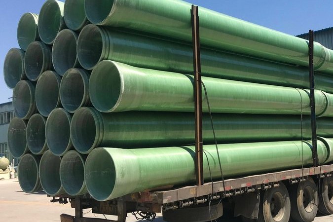
FRP ductwork is usually specified on corrosion resistance and support spacing. The expansion joint is added late, often as an afterthought during site installation, and it is then sized on a rule of thumb borrowed from steel ductwork. That is how a duct run that was designed for 20 years of service develops a flange leak at the first hot start-up, or a fabric belt that tears within six months.
The problem is not the joint. It is that FRP moves differently from steel in a way that changes the numbers by a factor most engineers do not expect, and that the joint is the element which then has to absorb the difference. This guide works through the movement, the guide spacing, the flange load and the field details for FRP duct runs, using a DN800 case study with arithmetic generated from a calculation script.
1. Why FRP Ductwork Needs an Expansion Joint at All
The common assumption is that FRP ductwork does not need expansion joints because FRP is flexible. The flexibility argument is half right and completely misleading.
- FRP elongates more than steel, not less. The axial coefficient of thermal expansion of a typical biaxial FRP laminate is around 20 x 10-6/°C, against roughly 12 x 10-6/°C for carbon steel. ASME B31.3 places FRP at up to 2.5 times carbon steel and up to 1.67 times stainless steel - and for filament-wound construction the hoop coefficient is close to steel while the axial coefficient is about twice steel, because the fibres are laid to carry hoop pressure rather than axial load.
- The force is small, but the displacement and the stress are not. Because the restrained thermal force is proportional to the product of modulus and expansion coefficient, and FRP's axial modulus is roughly one-tenth of steel's, a fully restrained FRP run generates only about an eighth of the force a steel run would. Designers see a small force and conclude that restraint is harmless. It is not: the stress is set by the product of modulus, expansion coefficient and temperature rise alone, so an FRP duct at 20 x 10-6/°C and 12 GPa is stressed just as seriously as a steel duct at 12 x 10-6/°C and 200 GPa, relative to its much lower allowable.
- There is no yield to relieve it. A steel duct that is slightly over-restrained will yield locally. An FRP duct that is over-restrained will either crack at a flange bolt hole, delaminate at a field joint, or snake sideways between supports.
A duct expansion joint on an FRP system is not there to reduce force. It is there to make displacement compatible. Getting that distinction wrong is the single most common cause of joint-related failures on FRP ductwork.
2. Thermal Movement Arithmetic for an FRP Duct Run
Two equations do most of the work. Free elongation is dL = alpha x L x dT. If the run is fully restrained at both ends, the force is F = A x E x alpha x dT, where A is the wall cross-section and E the axial modulus.
| Quantity | DN800 FRP duct | Carbon steel equivalent |
|---|---|---|
| Outside diameter / wall | 800 mm / 8 mm | 800 mm / 6 mm |
| Run length between fixed points | 30 m | 30 m |
| Installation / operating temperature | 15 °C / 90 °C | 15 °C / 90 °C |
| Axial expansion coefficient | 20 x 10-6/°C | 12 x 10-6/°C |
| Free thermal movement | 45.0 mm | 27.0 mm |
| Movement per metre of run | 1.5 mm/m | 0.9 mm/m |
| Wall cross-section | 0.0199 m² | 0.0150 m² |
| Axial modulus | 12,000 MPa | 200,000 MPa |
| Fully restrained force | 358 kN | 2,694 kN |
| Restrained axial stress alpha E dT | 18.0 MPa | 180 MPa |
The comparison is the point, and it cuts both ways. Fully restrained, the FRP run develops 358 kN and the steel run 2,694 kN - 7.5 times more force - because the force is proportional to the product of modulus and expansion coefficient. The stress tells a different story: 18.0 MPa for FRP against 180 MPa for steel, exactly the ten-to-one ratio of their moduli. On a typical 25 MPa long-term axial allowable for biaxial GRP, the FRP duct is at 72 % of its allowable with nothing left for pressure, weight or misalignment, while the steel duct is at 180 MPa against a room-temperature allowable nearer 137 MPa.
The lesson is that a low force does not mean a low stress. The FRP duct is not safer than the steel duct in a fully restrained run; it merely fails differently, and it fails with less warning because the laminate does not yield first.
Two consequences follow for the specification:
- A 30 m straight FRP duct run at 75 K temperature rise cannot be rigidly anchored at both ends unless the axial allowable is confirmed by the laminate supplier for that duty. Provide a joint, a change of direction, or both.
- Practitioners commonly treat 60 °C as the operating temperature above which a formal flexibility analysis is carried out for FRP duct and piping runs. Above that point, calculating the movement is not optional, and the calculation must use the axial modulus of the actual laminate schedule rather than a generic value.
The method above was validated against a published example for a 50 m GRP pipe run (OD 219.1 mm, wall 8.18 mm, 60 K rise, alpha 22 x 10-6/°C, E = 12 GPa): the script returns 85.83 kN against the published 85.84 kN, an error of 0.006 %.
3. The Four Joint Types and What Each One Actually Does
FRP systems are not limited to one joint type, and the choice is usually made on movement direction and temperature rather than on price.
| Type | Movement taken | Practical range | Watch out for |
|---|---|---|---|
| Fabric belt joint (non-metallic) | Axial, lateral and angular simultaneously | Low pressure, typically up to about 0.5 bar; temperatures from 150-250 °C with coated fibreglass up to 1100-1200 °C with ceramic layers | The fabric carries the pressure thrust itself, so belt width and ply count become a pressure-containing item |
| Rubber arch joint | Axial plus lateral and angular | Rated around 1-6 bar depending on size; EPDM covers to about 120 °C, nitrile to roughly 80-100 °C | Elastomer must be as chemically resistant as the duct; UV degradation on outdoor runs |
| Metal bellows (tied or untied) | Axial only when untied; tied variants take lateral and angular | Higher pressure and temperature; designed to EJMA and fabricated to ASME B31.3 or GB/T 12777 | An untied bellows passes the full pressure thrust to the anchors; the spring rate must be low relative to the FRP duct stiffness |
| Sleeve or slip joint | Axial only | Low pressure, low temperature | Not gas-tight; used for covers and non-critical air service only |
For large rectangular or round FRP exhaust ducts the fabric belt is usually the right answer, because it can absorb large movements in every direction at once and it removes the spring-force problem that makes metal bellows difficult to apply to low-modulus FRP. The trade is that the fabric becomes the pressure boundary.
4. Movement Classification: Axial, Lateral, Angular and Torsion
Published fabric joint data is normally quoted per belt width, and the numbers show how much capacity a modest belt provides.
| Belt width | Axial compression | Axial extension | Lateral offset | Coverage of the 45 mm case |
|---|---|---|---|---|
| 12 in. (305 mm) | 114 mm | 64 mm | 64 mm | 39 % of compression capacity used |
| 18 in. (457 mm) | 152 mm | 76 mm | 102 mm | 30 % used |
| 24 in. (610 mm) | 152 mm | 102 mm | 127 mm | 30 % used |
Typical published capability for fabric joints is of the order of 20-120 mm axial, 10-60 mm lateral, 15-30° angular and 5-10° torsional, depending on design. Two rules follow from the fact that these numbers are not additive:
- Do not spend the whole allowance on thermal movement. Installation misalignment, vibration amplitude from the fan and differential settlement all consume the same capacity. Designing the 45 mm case into a belt that offers 114 mm is sensible; designing 100 mm of movement into the same belt is not.
- State the governing movement case, not the sum. A joint that must take 45 mm axial and 10 mm lateral simultaneously is a different specification from one that sees each in isolation, and the supplier needs to see the combination.
5. Selecting Belt Width, Ply Build and Chemistry
A fabric joint is a layered composite, and each layer has a job. Specifying it as "a flexible connector" is how joints get supplied with a sealing layer that is chemically wrong for the duct.
| Layer | Function | Typical material by temperature band |
|---|---|---|
| Inner gas-side layer | Abrasion and chemical resistance against the stream | Coated fibreglass 150-250 °C; silica and basalt build-up 450-550 °C; silica fabrics 700-900 °C; ceramic Al2O3/SiO2 fabrics 1100-1200 °C |
| Insulation layer | Keeps outer layers below their limit | Basalt or silica blanket, or a separate insulation pillow |
| Compensation layer | Carries the movement and the axial pressure load | Reinforced fabric plies; ply count sets both movement and pressure rating |
| Outer cover | Weathering, UV and mechanical protection | PTFE, silicone or elastomer coated fabric |
| Flow liner / sleeve | Protects the fabric from erosion and from accumulation | FRP or stainless liner; specified where velocity or particulate loading is high |
Two specification points are easy to miss. First, the inner layer must be qualified against the same chemical list as the duct corrosion barrier, not merely against temperature. A joint with a perfectly heat-resistant layer that swells in a solvent vapour will fail as surely as one that burns. Second, where the stream carries dust or condensable material, a flow liner or accumulation barrier is not an accessory - it is what keeps the joint from being abraded or blocked solid.
6. Anchors, Guides and the EJMA Spacing Rules
A joint only works if the duct around it is guided. The established practice, from the expansion joint industry and carried into duct applications, is a simple geometric rule that is easy to inspect on site.
- First guide: within four duct diameters of the joint.
- Second guide: within fourteen duct diameters of the first guide.
- Subsequent guides: at intervals determined by the buckling calculation for the run.
For the DN800 case study, that means the first guide within 3.2 m and the second within 11.2 m of the first. Guides must restrain lateral movement while allowing axial movement - a support that clamps the duct is not a guide, it is an anchor, and it will convert thermal growth into a shell stress.
A column-buckling screen over that 11.2 m span is worth doing because the answer is counter-intuitive. The second moment of area of the DN800 x 8 mm section is 0.00156 m⁴, giving an Euler load of 1,474 kN at ambient and 1,032 kN at 90 °C once the modulus is reduced by 30 %. Both are well above the 358 kN restrained thermal force, with ratios of 4.1 and 2.9. Global buckling of a well-guided FRP duct run is therefore not the governing problem - which is precisely why the guide rules still have to be followed: they protect against squirm at the joint, local flange bending and vibration, not against column failure. The real risk of omitting guides is not collapse, it is a fatigue crack at the flange or a torn joint.
7. Pressure Thrust: When It Matters and When It Does Not
An untied metal bellows cannot transmit axial pressure load, so the anchors on both sides must be designed for the full pressure thrust, P x A. That number reaches tonnes on a high-pressure pipe line. On low-pressure FRP ductwork it is negligible, and knowing this changes the anchor detailing.
| Duct pressure | Flow area (DN800) | Pressure thrust | Share of the restrained thermal force |
|---|---|---|---|
| 500 Pa (2 in. wg) | 0.503 m² | 251 N | 0.07 % |
| 1,250 Pa (5 in. wg) | 0.503 m² | 628 N | 0.18 % |
| 7,500 Pa (30 in. wg) | 0.503 m² | 3,770 N | 1.05 % |
At the full 30 in. wg pressure class covered by ANSI/SMACNA 011-2017, the pressure thrust on a DN800 duct is under 4 kN against a 358 kN restrained thermal force. The conclusion is that on low-pressure FRP ductwork the anchors are governed by the thermal and dynamic loads and by the joint spring force, not by pressure thrust. Anchors sized for a steel-pipe bellows would be roughly two orders of magnitude over-designed.
The exception is a fabric joint, where the belt itself must be rated for the axial pressure load. That is why published fabric joint pressure limits sit around 0.5 bar rather than 5 bar, and why ply count is a pressure decision as well as a movement decision.
8. Flange Selection: Class I or Class II, and How Much Torque
This is where FRP ductwork most often goes wrong, because the flange at the joint is selected on drill pattern rather than on load path.
ASTM D5421-23 covers contact-moulded FRP flanges and divides them into two capability classes: Class I, which is qualified for hoop and axial pressure, and Class II, which is qualified for hoop pressure only. Grades run from 1 to 5 covering epoxy, polyester, phenolic, vinyl ester and furan resins, and the standard requires performance testing for sealing, short-term rupture strength and maximum bolt torque. The flanges are intended for pipe and tanks made to the contact-moulded and filament-wound specifications in the same family.
A flange at an expansion joint sees axial load. A Class II flange, qualified for hoop pressure only, is the wrong component regardless of whether the bolt holes line up. Specify Class I where the flange carries the joint reaction, and keep the maximum bolt torque inside the value the flange was tested for.
The torque question is best understood in numbers. On a DN800 flange with 20 M16 bolts and a 20 mm wide gasket on an 840 mm mean diameter, the seating stress developed at FRP-appropriate torque is modest:
| Torque per M16 bolt | Clamp load per bolt | Stress under the washer face | Gasket seating stress |
|---|---|---|---|
| 30 N.m | 9.4 kN | 19.5 MPa | 3.6 MPa |
| 45 N.m | 14.1 kN | 29.3 MPa | 5.3 MPa |
| 70 N.m | 21.9 kN | 45.6 MPa | 8.3 MPa |
| 100 N.m | 31.3 kN | 65.1 MPa | 11.8 MPa |
Two conclusions come out of that table. Taking a flange from 45 N.m to 100 N.m multiplies the clamp load by 2.22, which is how bolt holes in contact-moulded flanges crack - not because the steel bolt failed, but because the laminate around the hole was crushed. And even at the higher torque, the gasket stress only reaches about 12 MPa, so a gasket that needs a conventional steel-flange seating stress of 20-30 MPa will never seal on an FRP flange. Specify a low-seating-stress gasket, full-face where possible, and confirm the allowable torque from the flange supplier's test data rather than from a steel flange table.
Two field habits protect the joint: torque in a star pattern in at least three passes, and retorque after 24 hours and again at the first shutdown, because the laminate creeps under sustained bolt compression.
9. Flexible Connections at Fans: Where Most Vibration Enters the Duct
The flexible connector at a fan inlet or outlet does two jobs at once - thermal movement and vibration isolation - and it is frequently installed so badly that it does neither.
- The connector must not be the fan's ductwork. AMCA Publication 201 defines an effective duct length of 2.5 duct diameters at velocities up to about 2,500 fpm (12.7 m/s), plus one additional diameter for each further 1,000 fpm; a centrifugal fan needs the full effective length on its outlet and a vane-axial fan about half. Installing a soft connector right at the fan and then turning immediately is a system effect problem dressed up as a flexibility problem.
- Inlet elbows need distance. AMCA 201 recommends elbows at least three duct diameters upstream of a fan inlet, and notes they can cause system effect up to five diameters away.
- Install the connector slack, aligned and unloaded. Cold alignment within about 1.6 mm is the working target. A connector installed stretched, or pulled sideways to make up a misalignment, has already used part of its movement capacity before the duct reaches operating temperature.
- Remove shipping restraints before start-up. Joints and bellows ship with tie rods, transit bars or temporary spacers. Leaving them in is the single most common installation error on any expansion joint, and it converts a flexible element into a rigid one.
10. Installation, Leak Testing and the First Shutdown
FRP duct installation is a lamination job, not a bolting job, and the joint is affected by everything around it. ANSI/SMACNA 011-2017 covers the construction of hand lay-up, spray-up and filament-wound FRP ductwork across a range from 30 in. wg negative to 30 in. wg positive pressure, in round sizes up to 96 in. diameter, and includes chapters on hanger and support selection, duct sealing, duct leakage and an appendix on allowable FRP defects - which is the document to reference for acceptance criteria rather than a general visual inspection note.
- Verify the duct before lifting. Check flange face flatness with a straight edge, and measure ovality at both ends of each section; a section that is out of round will not bolt up, and forcing it cracks the flange.
- Keep field joints dry and warm. Laminating at low ambient temperature or on a damp, amine-blushed surface is the classic cause of a field joint that delaminates within a year.
- Support at the right spacing. FRP duct typically needs support at 1.5-3 m intervals depending on diameter - roughly half the spacing of steel duct. Use the supplier's or the SMACNA hanger table, not a steel duct standard.
- Test leakage before insulation. Establish the leakage class against the SMACNA criteria at the duct's pressure class, and record the result. Once the joint is insulated, a leak is invisible until it has damaged the insulation and the structure behind it.
- Check the corrosion barrier at every field joint. Laminate hardness against a reference coupon (Barcol method) and a documented visual acceptance to the allowable-defect criteria close out the corrosion liner; a pinhole in the liner at a joint attacks the structural laminate from behind, and the duct usually leaks two years later rather than two weeks later.
11. Maintenance, Cycle Counting and Spares
Fabric and elastomer joints have a finite life, and it is governed by cycles more than by calendar age. Counting cycles at the design stage turns a vague "inspect regularly" instruction into a real replacement plan.
| Duty | Cycles in 30 years | Movement per cycle | Planning implication |
|---|---|---|---|
| Continuous operation, one shutdown per day | 10,950 | 45 mm | Standard fabric joint life is realistic; inspect annually |
| Two cycles per day (day/night process) | 21,900 | 45 mm | Confirm cycle rating in writing; keep a spare belt on site |
| Four cycles per day (batch process) | 43,800 | 45 mm | Joint becomes a planned consumable; design for replacement access |
Design for the replacement before you need it: leave the joint accessible, do not insulate over the belt without a removable cover, keep the flange faces clean during the swap, and hold one spare belt in the store. A fabric belt can be replaced in hours; a delaminated duct section cannot.
Where the run is cooled below the dew point or shut down in winter, the joint must also be protected against condensate freezing in the fabric and against water sitting on the belt. That detail sits with the rest of the winterisation design rather than with the joint supplier.
Related reading on this site: FRP duct and hood fabrication covers wall thickness, stiffeners and support for large spans; ventilation duct installation, air resistance and sealing covers joint sealing and pressure testing; scrubber and absorber internals covers the equipment these ducts usually connect to; FRP flue and chimney liners covers hot exhaust runs; pipe support spacing and hanger design sets out the span and guided-fixing logic that duct support borrows from; and cooling tower winterisation covers the cold-weather side. For the duct and flue products themselves, see our FRP ventilation duct and FRP flue ranges.
Need help selecting FRP products?
Our engineers answer technical questions free of charge.
Ask an Engineer on WhatsApp