
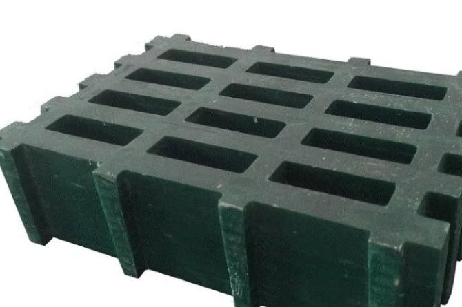
Outdoor FRP walkways, platforms and stair treads in Canada, the northern United States, Scandinavia and high-altitude industrial sites face a combination that mild-climate plants never see: deep design snow, radial ice from freezing rain, months of daily de-icing salt application, and temperature swings of 60–70 K between a January night and a July afternoon. Fibre-reinforced polymer (FRP/GRP) grating handles this combination better than most metals — but only if the designer understands which checks actually govern. Snow and ice are loads, salt is a chemistry problem, freeze-thaw is a durability problem, and glazed ice is a slip problem that no lab rating fully captures. This guide walks through each of those checks with the standard clauses, the published research data and the arithmetic you need to defend a specification.
1. Why Cold Climates Change the Specification
In a temperate petrochemical plant, FRP grating selection is usually driven by chemical zone, span and fire rating. Move the same walkway to an unheated tank farm at 3,000 m elevation or a wastewater plant in Alberta and the governing questions reorder. First, the design snow load on an unheated structure can exceed 3 kPa — nearly ten times the self-weight of the grating itself. Second, freezing rain coats every bar and rail with radial ice that adds weight, enlarges wind area and destroys slip resistance at the same time. Third, the de-icing salt applied for eight months of the year creates a chloride environment that metals survive only with coatings, cathodic protection or stainless alloys, while FRP is essentially indifferent to it. Fourth, every coating system you would normally rely on — paint, galvanizing, thermal spray — becomes a maintenance liability once freeze-thaw cycling and abrasives start attacking the coating itself. FRP's colour-through pultrusion and molded surfaces carry no coating to fail, which is precisely why cold-climate utilities switched to composite grating decades ago.
A rule of thumb that holds up in practice: in cold climates the load side (snow, ice, ice-enlarged wind) governs the structure, while the environment side (salt, freeze-thaw, slip) governs the material and surface selection. Check both — they rarely fail in the same member.
2. Design Snow Loads on Unheated Walkways: ASCE 7-22 Basics
ASCE 7-22 Chapter 7 converts ground snow load pg into a flat-roof snow load with pf = 0.7·Ce·Ct·pg. Two 2022-edition details matter for walkway designers. First, the snow importance factor Is has been removed from the equation; instead, the ground snow maps are now published separately for each Risk Category, so a Risk Category III process platform reads a higher pg directly from its map. Second, the thermal factor Ct now ranges from 0.85 to 1.3; an unheated, ventilated structure takes Ct ≈ 1.2, and a freezer building takes 1.3. An outdoor walkway is the definition of "unheated", so design it with Ct = 1.2 at minimum.
Worked values (exposure factor Ce = 1.0, partially exposed, terrain C):
| Ground snow pg | Flat-roof pf = 0.7·Ce·Ct·pg | Equivalent snow depth* | Approx. mass |
|---|---|---|---|
| 20 psf (0.96 kPa) | 16.8 psf (0.80 kPa) | 0.31 m | 82 kg/m² |
| 30 psf (1.44 kPa) | 25.2 psf (1.21 kPa) | 0.43 m | 123 kg/m² |
| 50 psf (2.39 kPa) | 42.0 psf (2.01 kPa) | 0.62 m | 205 kg/m² |
| 80 psf (3.83 kPa) | 67.2 psf (3.22 kPa) | 0.84 m | 328 kg/m² |
*Equivalent depth uses the ASCE 7-22 Eq. 7.7-1 snow density γ = 0.13·pg + 14 pcf (≤30 pcf), which gives 20.5 pcf (3.22 kN/m³) at pg = 50 psf. The density matters when you convert a snow depth reading into a load: 0.6 m of settled northern snow is not 60 kg/m² — it is roughly 200 kg/m².
Two consequences for grating spans. A 38 mm molded grating weighs roughly 23 kg/m², so the 50 psf design snow is about 8.9 times the dead load — the span tables that govern at 2 kPa are not the ones in the mild-climate brochure. And while open mesh sheds loose snow, wind-packed and stepped-on snow bridges the mesh and stays; treat the walkway as a solid surface for snow accumulation, exactly as the load tables for grating walkways assume.
3. Ice: The Second Load You Must Carry
ASCE 7-22 Chapter 10 quantifies freezing-rain ice. The design ice density is at least 56 pcf (8.80 kN/m³) (§10.4.1), the nominal radial thickness t comes from the Fig. 10.4-2 maps (50-year mean recurrence, Risk Category II), and the weight on a flat plate follows Eq. 10.4-2, Vi = (π·td/12)·As, with a 0.6 multiplier for horizontal plates and 0.8 for vertical plates. For a walkway deck treated as a horizontal plate, the ice pressure simplifies to q = γice·π·td·0.6:
| Radial ice td | Ice load on horizontal deck | Equivalent mass | vs. 38 mm grating self-weight |
|---|---|---|---|
| 10 mm | 0.17 kPa (3.5 psf) | 17 kg/m² | 0.7× |
| 25 mm | 0.41 kPa (8.7 psf) | 42 kg/m² | 1.8× |
| 50 mm | 0.83 kPa (17.3 psf) | 85 kg/m² | 3.7× |
On members, Eq. 10.4-1 adds ice to the circumscribing diameter Dc: a 60 mm handrail carrying 25 mm of radial ice picks up about 6.0 kg/m of ice (58.7 N/m); a 114 mm post picks up 9.8 kg/m. These are the numbers that matter for handrail posts, which were typically sized for a 0.3 kN concentrated load and never checked for ice weight — a 25 mm icing event on a 10 m railing run adds roughly 60 kg of dead load in the worst possible place: cantilevered off the platform edge.
Note the relative magnitudes: 25 mm of glaze ice (42 kg/m²) is real but modest — about a fifth of the 50 psf snow. Ice becomes critical not through weight alone but through the next two effects: it enlarges wind area, and it eliminates slip resistance.
4. When Open Grating Becomes a Solid Sail: The Iced Solidity Ratio
ASCE 7-22 applies the same logic to wind that it does to weight: ice grows on every free edge. For open structures, the solidity ratio ε is recomputed with the design ice thickness added to each member face, producing the iced solidity ratio ε'. Once ε' > 0.7, the fence or grating is treated as a solid surface for wind loading — the wind area no longer sees through the mesh.
The arithmetic for a typical molded grating is sobering. Take 25 mm bearing bars at a 30 mm clear gap: the clean solidity is 25/55 = 0.45. With 25 mm of radial ice on every exposed face, the iced geometry is 75 mm of bar over a 105 mm pitch: ε' = 0.71 — solid. The same grating with only 10 mm of ice stays open at ε' = 0.60, and a light 5 mm I-bar section with 25 mm of ice reaches 0.65, still open. The design consequence: on freezing-rain sites, check wind loads on platform screens, gates and tall grating elements in the iced condition, because the worst wind-and-ice combination converts your open structure into a billboard.
5. Freeze-Thaw Durability: What the Research Actually Shows
Concrete spalls in freeze-thaw because water fills its pores, expands about 9 % on freezing, and bursts the matrix from inside. GFRP laminates absorb only about 0.1–0.7 % water by weight (ASTM D570), so the frost-jacking mechanism is essentially absent — if the laminate stays dense. The published cycling studies support this with useful nuance:
- Dry pultruded GFRP is nearly immune. In a 300-cycle thermal cycling study (20 °C to −10 °C) on pultruded GFRP published in Composite Structures (Grammatikos et al., 2016), dry specimens showed negligible change in tensile and in-plane shear properties after 300 freeze-thaw cycles, with only a minor drop in glass transition temperature.
- Saturated GFRP is the case to design against. In the same study, water-saturated specimens lost significant tensile and in-plane shear strength across the cycles, driven by thermal-stress mismatch between wet matrix and glass — while stiffness remained largely unaffected because the plasticization that softened the matrix was reversible.
- Freeze-thaw with salt solution is harsher. A Queen's University durability study of pultruded GFRP forms subjected 170 coupons to 300 freeze-thaw cycles (+5 °C to −18 °C core temperatures) and saw a 23 % reduction in coupon tensile strength — yet full-scale deck specimens showed no loss in ultimate capacity because the failure mode was governed by punching shear, not laminate tension.
- Hot salt water is the worst case, not the cold. In the same programme, 224 days of immersion in 3 % NaCl solution reduced tensile strength retention from 77 % to 63 % as temperature rose from 23 °C to 55 °C — accelerated-aging chemistry, not freezing, drives long-term loss.
Design translation: freeze-thaw itself is not the enemy of a well-made FRP grating — water ingress is. Specify a intact surface veil or gelcoat layer, seal every field cut with the resin or edge-sealant the fabricator recommends, and inspect cut edges annually. A dry laminate passes 300 freeze-thaw cycles with negligible change; a saturated one does not.
6. De-icing Salts: Chloride Chemistry and Material Selection
De-icing salt is the cold-climate environment in miniature: it is why walkway hardware, supports and adjacent steel corrode, and why the FRP-vs-steel decision is rarely close in northern sites. The three common chlorides differ in how low they work:
| De-icer | Practical effective temperature | Attacks | Does not attack |
|---|---|---|---|
| Sodium chloride (NaCl, rock salt) | ≈ −9 °C | Carbon steel, galvanizing (zinc), aluminium (pitting), concrete rebar via chloride ingress | GFRP, stainless 316, polyolefins |
| Magnesium chloride (MgCl₂) | ≈ −15 °C | Carbon steel; more hygroscopic — keeps surfaces wet longer, extending corrosion time | GFRP, stainless 316 |
| Calcium chloride (CaCl₂) | ≈ −29 °C | Carbon steel; exothermic dissolution can thermally shock some coatings | GFRP, stainless 316 |
(Effective temperatures per the FHWA anti-icing manual of practice; eutectic points are lower but irrelevant in practice.) Three points for specification. First, the corrosivity classification of a salted walkway environment is genuinely aggressive — chloride deposition from de-icing puts open steelwork in the same maintenance category as coastal exposure, and hot-dip galvanized gratings in salted environments commonly show first rust at cut edges within one to three winters. Second, FRP's immunity is molecular: the chlorides have nothing to oxidize. A vinyl-ester or isophthalic polyester matrix in NaCl/CaCl₂ splash zones is a decades-long material, not a coated one awaiting failure. Third, remember the fasteners: an FRP grating on carbon-steel clips is a galvanic and corrosion problem reintroduced through the back door — specify 316 stainless or FRP clips, and seal the contact faces.
7. Slip on Ice and Frost: What R-Ratings Cannot Promise
Slip ratings test wet surfaces, not ice. DIN 51130 grades walkway surfaces from R9 to R13 by the ramp angle a test subject can walk: roughly R9 at 6.4° (tan 0.11), R11 at 19.2° (tan 0.35) and R13 at 35° (tan 0.70); EN 16165 is the current European measurement standard behind those grades. A gritted FRP grating reaches R12–R13 wet — genuinely among the best walkway surfaces available. But glaze ice ignores grit: the friction coefficient of a shoe on smooth wet ice runs from about 0.05 to 0.15, equivalent ramp angles of 2.9° to 8.5°. Even the best R13 surface, once ice films it, behaves between below-R9 and barely-R10. No pedestrian surface rating fixes this, because the problem is a lubricating film, not texture roughness.
- Drainage is the first anti-icing measure. Ice forms where meltwater ponds. Set a minimum fall (about 1–2 %) on platform surfaces and keep the mesh open so water leaves before it freezes.
- Grit still matters at the margins. Near 0 °C, a thin water film on gritted FRP retains far more traction than the same film on smooth steel or grating; the danger zone is the glazed state below about −5 °C.
- Manage the film, not the rating. Anti-icing (salt brine applied before the event) prevents glaze from bonding; mechanical removal with plastic-edged shovels avoids gouging the surface; heated walkway mats are the fix for choke-point areas that cannot be closed.
- Close the walkway in glaze events. The engineering answer no rating can override: an iced grating is a hazard regardless of material, and access control beats litigation.
8. Low-Temperature Material Behaviour and Resin Choice
Pultruded and molded FRP gratings are routinely rated for continuous service from about −40 °C upward; the polymer matrix stiffens and slightly gains short-term strength as temperature drops, trading a little toughness. The design check is not the cold itself but the margin between service temperature and the resin's glass transition temperature on the hot end, plus impact behaviour on the cold end. Two practical rules:
- Keep operating temperature well below Tg. As with all thermoset design, hold the sustained service temperature at least 20–25 K below the resin Tg. In cold climates this is trivially satisfied — the hot side (40 °C sun on a dark surface) is the binding constraint, not the cold.
- Choose resin by chemistry, then by toughness. Isophthalic polyester is the economical default for salt-splash and atmospheric service; vinyl ester earns its premium where salt spray combines with chemical exposure, higher temperatures, or where you want the higher elongation (better impact tolerance at low temperature) that vinyl-ester networks provide. For the general selection logic between resin families, see our vinyl ester vs isophthalic comparison.
Surface matters in the cold for a second reason: UV. Winter sun at low angles plus snow albedo doubles the UV dose on horizontal grating surfaces, so an outdoor panel in a northern site needs a UV-stabilized veil or gelcoat just as a desert panel does — the failure mode is surface fibre bloom, not structural loss.
9. Thermal Movement, Gaps and Installation Detailing
FRP's coefficient of thermal expansion is direction-dependent: roughly 10 × 10⁻⁶/K along pultruded rovings and 25–30 × 10⁻⁶/K across them (ASTM D696), the transverse value being about 2.5 times that of carbon steel. Over a −30 °C to +40 °C operating swing (70 K), the arithmetic gives:
| Element | Direction | Length | ΔL at 70 K |
|---|---|---|---|
| Pultruded bearing bar / panel length | longitudinal (α ≈ 10 × 10⁻⁶/K) | 3.0 m | 2.1 mm |
| Panel width, molded mesh | transverse (α ≈ 30 × 10⁻⁶/K) | 1.0 m | 2.1 mm |
| 10 m run of panels, abutted | transverse | 10 m | 21 mm |
The installation rules follow directly. Provide a 5–10 mm clearance gap between adjacent panels so each can move without shingling; never butt panels tight against steel frames, which move less than half as much and will pinch the composite at minimum temperature. Clip every panel edge per the manufacturer's pattern — typically one clip per 300–600 mm of edge — using the M- or C-clips in 316 stainless, and re-torque after the first thermal cycle. Long runs should carry an expansion joint every 10–12 m in the transverse direction. Field-cut panels must have every cut edge sealed; the mesh openings are generous enough that thermal movement never binds the mesh itself, which is one of the quiet advantages of open grating over solid plate in variable climates.
10. Winter Operation and Maintenance Practice
A cold-climate grating specification is only as good as its operating regime. The practices that keep installations sound for decades:
- Snow removal with plastic edges. Steel blades gouge the grit surface and can expose glass fibres; polyethylene-edged shovels and nylon bristles clean effectively without cutting the veil.
- Anti-ice before it bonds. Pre-storm brine or salt application prevents glaze adhesion and turns every subsequent removal task from chiselling to sweeping — dramatically less surface damage over a season.
- Annual spring inspection. After the last thaw, walk every platform: look for fibre bloom on high-traffic panels, loose or corroded clips (the hardware, not the grating, is the usual culprit), cut edges that lost their seal, and any panel that took visible impact from ice-removal equipment. Grading damage against the same defect categories used for routine grating inspections keeps the record continuous.
- Re-seal and spot-replace. Edge sealant is a five-minute repair; replacing a single panel takes minutes with a clip system. Budget both as routine line items, not projects.
- Keep the drainage working. The single biggest durability lever in freeze-thaw climates is preventing water from standing on or under the walking surface — clear the drains, keep the mesh open, and ice gets one fewer place to start.
Specify FRP Grating for Cold-Climate Sites With Confidence
Snow load with Ct = 1.2, ice per ASCE 7-22 Chapter 10 with the iced solidity check, sealed cut edges, chloride-rated resin, 316 stainless hardware, real drainage and a winter maintenance plan — that is the complete checklist, and none of it is exotic. We supply molded and pultruded FRP gratings with grit surfaces, vinyl-ester and isophthalic resin options and Class 1 fire-rated formulations for exactly these environments. Send us your span, load and site temperature range, and our engineering team will return the panel selection, clip layout and span table back-up within one working day.
Related reading: FRP Grating Load Tables: Reading Uniform and Concentrated Loads · Stair Tread Slip Resistance Standards for FRP Walkways · FRP Grating Fabrication and Installation: Field Cutting and Clip Fixing · FRP Resin Selection: Vinyl Ester vs Isophthalic Polyester · Product pages: FRP grating, walkways and stair treads · Molded FRP grating for walkway flooring
Need help selecting FRP products?
Our engineers answer technical questions free of charge.
Ask an Engineer on WhatsApp