
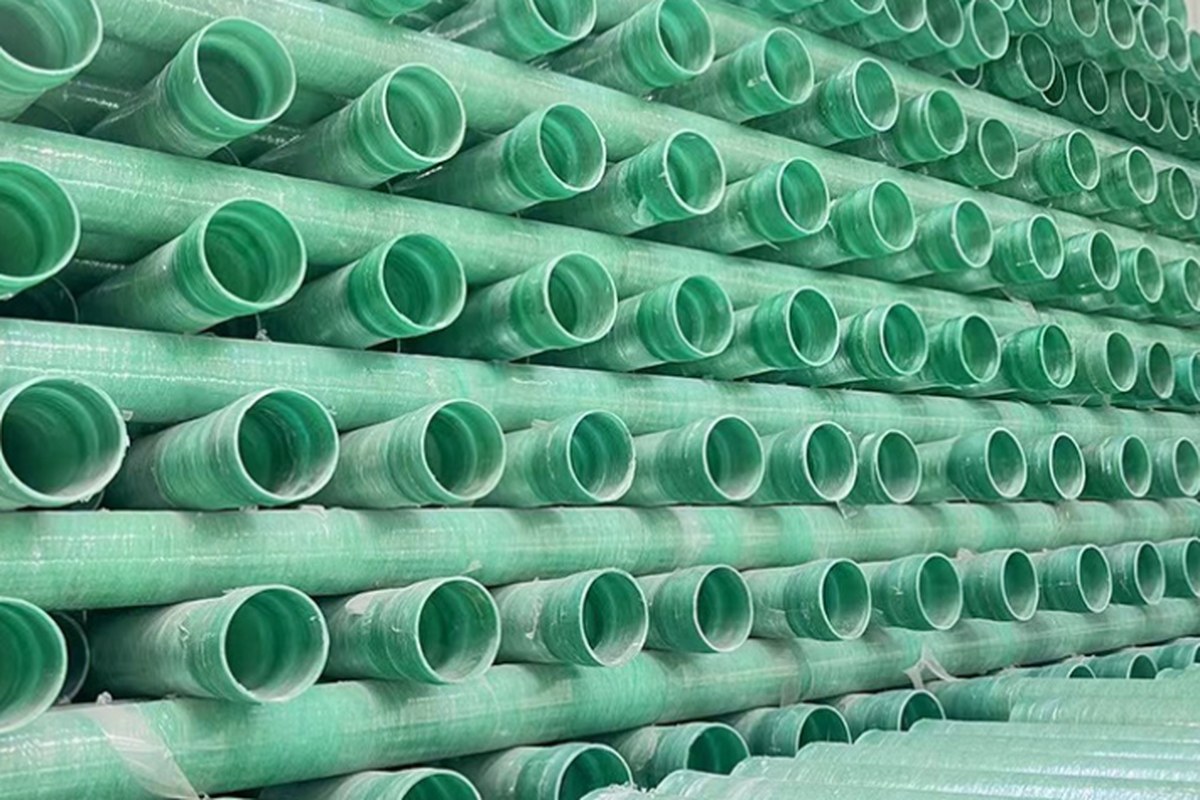
A fire main is the one line in a plant that is expected to sit essentially unused for years, then deliver its full rated flow on the worst day of the asset's life - with nobody standing by to open a bypass if something goes wrong. That duty profile is what makes fire water a genuinely different specification problem from a process line, and it is also why glass-reinforced plastic pipe has quietly moved from a niche material into mainstream fire-service use: sea-water fire mains on marine and offshore installations, deluge ring mains, tank-farm and terminal fire mains, power station and desalination fire water. The driver is not cost. It is the fact that internally corroding steel fire mains scale up, plug hydrant outlets, deluge nozzles and sprinkler heads, and leave a system that passes its annual flow test while quietly losing the ability to extinguish anything.
FRP does not solve that problem automatically. An FRP fire main is only as good as the pressure envelope it was qualified for, the joints that hold it together, the burying and restraint behind it, and the code path the project accepted. This guide sets out the numbers an engineer actually needs: the standards that govern the pipe and its installation, how FRP pressure ratings are built from long-term regression data, why the hydrostatic test is usually the load case that picks the pressure class, what a deluge valve does to the line in the first second it opens, and how flushing and acceptance testing are executed on site.
1. Why Fire Water Is a Harder Duty Than a Process Line
A process line runs continuously. Its design case is the operating case, its temperature is known, its flow is known, and a failure usually announces itself through a leak, a pressure drop or an analysis result. A fire main runs intermittently at best. Water may sit nearly static against the corrosion barrier for two or three years between flow tests, at ambient soil temperatures that in hot climates stay in the 30-40 °C band. Then, without warning, the line goes from zero flow to design flow in seconds when a deluge valve opens or a fire pump starts.
That single sentence contains three separate load cases that FRP treats differently:
- Sustained load - the static system pressure that sits in the pipe for decades, plus soil and traffic load if buried.
- Cyclic load - repeated pressurisation from pump starts, annual flow tests, hydrant testing and flushing. On a 30-year asset this can be a few hundred cycles, which matters for a material whose long-term strength is defined by stress rupture.
- Occasional or transient load - the surge that accompanies rapid valve opening or pump start, and any short-duration over-pressure during acceptance testing.
There are four further differences that shape material and detail selection, and they are worth stating explicitly because each one has caught out a project that specified FRP as if it were "corrosion-resistant steel pipe":
- The water is stagnant and often treated. Chlorinated or chloraminated fire water held against a general-purpose polyester liner for years is a hydrolytic and oxidative exposure, not a neutral one. Resin grade selection is a fire-main issue, not just a potable-water issue.
- Joints cannot be re-visited. Buried mains are backfilled once. A joint that weeps slowly will not be found by walking the line; it will be found by a void under the road or by a failed flow test. Bonded and laminate joints dominate for exactly this reason.
- The acceptance test exceeds the working pressure. A fire main designed for 10 bar static pressure is conventionally pressure-tested at 200 psi (13.8 bar), which means the test is frequently the governing load case for wall thickness and restraint design - not the operating condition.
- The pipe itself becomes a fire-exposure question above ground. Buried, the water inside carries heat away and the polymer never gets hot enough to matter. Above grade, on a rack or inside a pump house, the flame spread and smoke generation of the resin system become part of the fire engineering case.
| Parameter | Typical process line | Fire water / deluge main | Why the difference matters for FRP |
|---|---|---|---|
| Flow regime | Continuous, known | Static for years, then design flow in seconds | Cyclic and occasional envelopes must both be qualified, not just the sustained one |
| Design temperature | Set by process (often 60-90 °C) | Set by soil or ambient (10-40 °C typical) | Low temperature is favourable, but must be stated - ratings are quoted at 20 °C and de-rate with temperature |
| Governing pressure case | Operating pressure + surge | Field hydrostatic test pressure | The tested pressure has to be inside the qualified envelope of every joint and anchor |
| Fluid chemistry | Process fluid, characterised | Brackish, sea or chlorinated water | Corrosion barrier and resin grade become endurance questions, not just compatibility questions |
| Inspection access | Piping is often accessible | Buried and backfilled once | Joint quality and locate-ability (tracer wire) must be built in, not inspected in |
| Consequence of failure | Loss of production | System does not deliver water when needed | Reliability engineering, not cost engineering, drives the specification |
2. The Standards and Approval Routes That Actually Govern the Pipe
Fire-service FRP pipe sits at the intersection of two worlds: a materials specification world (ASTM, ISO, AWWA) that tells you what the pipe is and how its strength is qualified, and a fire installation world (NFPA and the approval bodies) that tells you how it must be installed, tested and listed. A specification that quotes only one of them will not survive plan review.
| Document | What it governs | The numbers worth knowing |
|---|---|---|
| UL 1713 - Pressure Pipe and Couplings, Glass Fiber-Reinforced, for Underground Fire Service | Lists RTRP and RPMP pipe and couplings for underground fire service, in connection with NFPA 24 installations | Pressure classes 100 / 150 / 200 / 250 psig and above (0.69 / 1.03 / 1.38 / 1.72 MPa); nominal inside diameters 4 in to 60 in |
| NFPA 24 - Installation of Private Fire Service Mains | Burial, restraint, flushing, hydrostatic testing, appurtenances, records | Hydrostatic test at the greater of 200 psi or working pressure + 50 psi, held 2 h within ±5 psi; flushing at not less than 10 ft/s until clear; tracer wire required for non-metallic pipe |
| NFPA 13 / 15 / 16 | Sprinkler, water spray and foam-water deluge systems | Set the demand the main must deliver (density × area, plus hose allowance) - and therefore the flow and pressure your FRP main has to pass |
| NFPA 20 / NFPA 25 | Fire pumps; inspection, testing and maintenance | Suction-side flushing per NFPA 20; periodic flow tests and valve exercising under NFPA 25 keep stagnant water moving |
| ASTM D2996 / D3517 | Filament-wound reinforced thermosetting resin pipe; filament-wound pressure pipe | Product specification for the pipe you are buying, independent of the fire listing |
| ASTM D2992 / D2412 / D1599 | Long-term hydrostatic regression; ring stiffness; short-term burst | The test basis behind published pressure and stiffness classes |
| AWWA C950 / AWWA M45 | Fiberglass pressure pipe for water supply; design manual | Municipal-class water pipe design basis, widely referenced for buried water mains and their leakage acceptance |
| ISO 14692-1 to -4 | GRP piping for the petroleum, petrochemical and offshore industries | Qualification via 20-year lower confidence limit, partial factors for temperature, chemical and cyclic exposure; field joint quality requirements in Part 4 |
Approval, as distinct from compliance, is where fire projects differ from every other pipe project. UL, FM, LPCB and VdS approvals are granted to a specific pipe-plus-coupling system from a specific manufacturer, built with a specific resin system and joined by a specific method. Substitute the resin, change the joint from adhesive-bonded to rubber-sealed, or mix pipe and couplings from two listings, and the approval no longer describes what is on site. Field experience in offshore firewater loops is unambiguous on this point: it is not unusual for a loop to fail within months of commissioning after a resin substitution that was never re-qualified. If a substitution is unavoidable, it is a re-qualification exercise, not a purchasing decision.
Insurance and authority requirements usually make approved products mandatory rather than optional: a single unlisted component can void the approval of the assembled system, and the assembled system - not the pipe - is what the approval covers.
3. Pressure Ratings: Sustained, Cyclic and Occasional Envelopes
A GRP pipe does not have "a pressure rating" in the sense a steel pipe does. It has a qualified envelope, derived from stress-rupture data, and the usable pressure depends on how long the load acts and what else is acting with it. Understanding this is the difference between buying the right pipe and buying an optimistic number.
The qualification route runs like this. Pipe samples are held under constant pressure at an elevated temperature - 65 °C or the design temperature if higher - for up to 10,000 hours, and the failure times are regressed on log stress against log time. The regression line is extrapolated to the 20-year point (about 175,400 hours) and reduced to a lower confidence limit, typically taken at 97.5 % confidence. That value is the long-term hydrostatic pressure; converted through the pipe geometry (qualified stress = pressure × mean diameter ÷ 2 × reinforced wall thickness) it becomes the first point on the failure envelope. Two further points come from a shorter uniaxial test and from the hoop-to-axial relationship, and the three define the shape of a bi-axial envelope.
The envelope is then reduced twice. First by partial factors for the difference between laboratory conditions and service: a temperature factor referenced to the glass transition temperature, a chemical degradation factor for the medium, and a cyclic factor for repeated pressurisation. Then by design factors that differ according to the loading condition, which is what produces three separate design envelopes:
| Load case | How a fire main experiences it | Envelope to design against | What to ask the supplier for |
|---|---|---|---|
| Sustained | Static system pressure held for the life of the asset | Sustained design envelope, with chemical factor applied for the actual water chemistry | Rated pressure at the stated design temperature, with the chemical factor declared |
| Cyclic | Pump starts, annual flow tests, hydrant tests, flushing - a few hundred cycles over 30 years | Cyclic design envelope | Cyclic rating and the assumed number of cycles it is based on |
| Occasional | Deluge activation, surge, and the 2-hour field hydrostatic test at 200 psi or working + 50 psi | Occasional / short-duration envelope | Confirmation that the field test pressure sits inside the occasional envelope for your pipe class |
Two practical warnings follow. First, a datasheet that says "PN 16" or "Class 250" is quoting one envelope, usually the sustained one, at a stated temperature. It says nothing about the transient case, and it says nothing about the elevated temperature at which it stops being true. Second, design temperature for a fire main should be stated honestly. Buried mains in hot climates sit at soil temperatures well above the 20 °C at which laboratory ratings are referenced, and FRP strength falls as service temperature approaches the glass transition temperature of the resin. Writing "20 °C" into a specification to obtain a comfortable pressure number is a way of deferring a problem into year seven of a 30-year asset.
4. Matching the Pressure Class to the Hydrostatic Test
This is the most common and most avoidable error in FRP fire-main specifications. The acceptance test required by NFPA 24 is the greater of 200 psi (13.8 bar) or the system working pressure plus 50 psi (3.4 bar), held for two hours with leakage within the permitted allowance and pressure held within ±5 psi. A 2-hour hold is not an instantaneous proof test: the pipe, the joints, the thrust restraint and the anchors are all experiencing a genuine sustained load, at a level above the operating case.
The consequence is simple arithmetic. If the test pressure is 200 psi, a Class 150 pipe is not a candidate, however comfortable its continuous rating looks. Class 200 is the practical minimum for a private fire main tested under NFPA 24, and many specifications default to Class 250 to keep margin for surge, for the case where a fire pump churn pressure raises the static value, and for the awkward test where the local authority insists on the +50 psi rule applied to a high static pressure.
| System working pressure | NFPA 24 test pressure (greater of 200 psi or +50 psi) | Minimum practical UL 1713 class | Note |
|---|---|---|---|
| 6 bar / 87 psi | 200 psi (13.8 bar) | Class 200, usually specified as Class 250 | Test case governs; the operating case is far below the rating |
| 10 bar / 145 psi | 200 psi (13.8 bar) | Class 200 / 250 | Common city-water-plus-pump case |
| 12 bar / 174 psi | 224 psi (15.4 bar) | Class 250 | +50 psi rule starts to govern |
| 16 bar / 232 psi | 282 psi (19.4 bar) | Above standard classes - project qualification required | Confirm against the short-term and occasional envelopes, not just the class label |
Two further checks belong in the same conversation. Mill hydrostatic testing at the factory is normally performed at a multiple of the rated pressure - the manufacturer's quality programme, not your acceptance test - and field testing is commonly conducted at 1.25 to 1.5 times design pressure depending on the project code. Both have to be inside the qualified envelope. And the test load has to be carried by the restraint system: bends, tees, reducers and dead ends must be blocked or restrained for the full test thrust, for the full two hours, before anyone signs the certificate.
5. Diameter, Stiffness and Wall Build-Up for Buried Fire Mains
An FRP pipe carries two independent structural requirements and both must be satisfied by different parts of the same wall. Pressure is carried by the hoop-directed reinforcement; external load, soil settlement and traffic loading are carried by the wall's ring stiffness. A pipe can be amply strong for 16 bar and still deflect unacceptably because the stiffness class was chosen for a deeper burial or heavier traffic than the project actually has.
Stiffness classes are quoted in newtons per square metre - SN 2500, SN 5000, SN 10000 - measured per the ring stiffness test method. Higher classes mean a stiffer wall, usually achieved with a thicker or differently built structural layer rather than with more hoop glass, and they come with a price and a weight penalty. For buried GRP water and fire mains, the practical installation check is deflection after backfill: many GRP specifications work to a limit of about 3 % of internal diameter at installation, tighter than the 5 % commonly used for thermoplastic pipe, because the GRP wall does not redistribute load into the soil in the same way. Deflection is a soil-and-bedding property as much as a pipe property, which is why a good specification describes the bedding and backfill in as much detail as the pipe.
Sizing is where the flushing requirement bites. NFPA 24 requires flushing at a velocity of not less than 10 ft/s (about 3 m/s) until the water runs clear, and that requirement sets the minimum flow a main must be able to pass with the available supply:
| Nominal diameter | Flow for 10 ft/s | Practical implication |
|---|---|---|
| 4 in (DN100) | About 390 gpm (88 m³/h) | Achievable from most supplies; typical for hydrant-only laterals |
| 6 in (DN150) | About 880 gpm (200 m³/h) | Common minimum fire main size; usually two hydrants wide open |
| 8 in (DN200) | About 1,560 gpm (354 m³/h) | Where the main also feeds sprinkler or deluge risers |
| 10 in (DN250) | About 2,440 gpm (554 m³/h) | Usually requires a dedicated flush connection |
| 12 in (DN300) | About 3,520 gpm (800 m³/h) | Flush connection sized for the velocity, not for convenience |
Where the available supply cannot deliver 10 ft/s, the standard solution is a dedicated, adequately sized flush connection - and in the current edition of NFPA 24, high-pressure pigging is also recognised as an alternative method of clearing a main. Both routes exist because construction debris, not water chemistry, is the most common cause of an obstructed fire main at commissioning.
The design advantage of FRP in the same calculation is friction. Glass-reinforced pipe has a smooth bore with a sand roughness of roughly 0.03 mm in Colebrook terms, and a Hazen-Williams C factor of about 150 that is retained for the life of the pipe rather than falling away as deposits accumulate. A 50-year-old FRP fire main is designed with substantially the same friction factor as a new one - which is exactly the failure mode that erodes the design margin of a steel main. Confirm the C factor and roughness to be used in your hydraulic model against the manufacturer's data, then use it consistently for both the flush case and the fire demand case.
6. Surge: The Load Case That Opens With the Deluge Valve
The moment a deluge valve releases, or a fire pump starts into a static main, the velocity in the line changes from zero to several metres per second in a fraction of a second. A pressure transient travels up and down the main at the acoustic wave speed of the pipe-and-fluid system, and the resulting pressure excursion is a design load that GRP handles differently from steel - in both directions.
The fundamental value is the Joukowsky pressure rise, ΔP = ρ · a · ΔV, where ρ is fluid density, a is wave celerity and ΔV is the change in velocity. Wave celerity in GRP pipe is typically in the range of about 300 to 600 m/s, against roughly 1,000 to 1,270 m/s for steel - the lower modular stiffness of the composite makes the pipe wall more compliant and slows the wave. Wave speed also depends on diameter, pressure class, wall construction and, for buried pipe, on the surrounding soil.
| Material | Modulus of elasticity (order of magnitude) | Typical wave celerity | ΔP for a 2 m/s velocity change |
|---|---|---|---|
| Carbon steel | About 200 GPa | 1,000-1,270 m/s | About 20-25 bar |
| Ductile iron | About 170 GPa | About 1,100-1,180 m/s | About 22-24 bar |
| GRP / FRP | About 10-25 GPa | 300-600 m/s | About 6-12 bar |
| PE100 (for comparison) | About 1 GPa | About 300 m/s | About 6 bar |
The critical time is t = 2L/a, the round trip for the wave to reach the far end of the line and return. For a 200 m main with a celerity of 500 m/s, that is 0.8 s. Deluge valve actuators and fire pump starts routinely act faster than that, which means most short fire mains experience close to the full Joukowsky excursion - the relief wave has not returned before the velocity change is complete. On long mains, where the valve acts slowly compared with 2L/a, the relationship becomes ΔP = 2ρLΔV/tc, in which the celerity cancels and the pipe material makes no difference to the surge magnitude at all. The useful engineering conclusion is that GRP's compliance is a real advantage for rapid events on short mains, and no advantage whatever for slow ones.
The direction of the transient matters as much as the magnitude, and this is where GRP deserves particular attention:
- Opening a deluge valve or starting a pump reduces velocity downstream and sends a downsurge upstream. A 10 bar downsurge on a main holding 8 bar drives the calculation into sub-atmospheric pressure, where dissolved air comes out of solution, vapour cavities form, and the rejoining of a cavity produces a shock that can exceed the original upsurge.
- Emergency valve closure or a pump trip produces the classical upsurge, the case most specifications remember to check.
- Sub-atmospheric pressure is a structural load in its own right for a thin-wall composite pipe, and a joint-integrity issue: rubber-sealed joints can draw in gaskets, and liners can separate locally under external pressure.
Mitigation is conventional but has to be designed rather than assumed: air and vacuum valves at high points, sized for the air inflow the transient analysis predicts; surge vessels or accumulators where the analysis shows a deep downsurge; slow-opening or staged deluge valves; soft-start fire pumps or pump flywheels to limit the rate of velocity change; non-slam check valves; and keeping the main wet and pressurised rather than drained, since starting a pump into an empty main adds its own problems. A transient study on the as-installed geometry - diameters, lengths, elevations, valve and pump response times - is the only way to get the numbers right, and it should be run before the pipe class is frozen, not after.
7. Joints and Thrust Restraint in a System That Must Hold for Decades
Reported service experience with GRP piping keeps returning to the same conclusion: joints, not pipe barrels, are where the problems are. That is precisely why the ISO 14692 series devotes an entire part to field joint quality, and why a fire-main specification should be more explicit about joints than about almost anything else in the pipe.
| Joint type | How it works | Angular deflection available | Best use in fire service | Main risk |
|---|---|---|---|---|
| Adhesive-bonded tapered spigot and socket | Machined taper, adhesive applied, held closed until cure | Small; a few tenths of a degree per joint | Buried mains - the default for water and fire water | Adhesive mixing, gap control, cure temperature; no re-work once buried |
| Laminated butt-and-strap | Field lay-up of resin and glass over a butt joint | Effectively none | Above-grade headers, tank connections, plant pipework | Requires controlled environment; humidity, dust and sunlight all degrade the bond |
| Rubber-seal lock joint | Integral gasket in a machined socket, pushed home | Useful - allows layout deflection and small ground movement | Where speed of installation dominates; requires restraint | Gasket displacement; joint must be restrained against separation |
| Flanged | Factory or field-laminated stub ends with gasket | None | Pump, valve and equipment connections | Bolt over-torque crushing the laminate; uneven gasket compression |
Restraint design follows from the thrust equation. At a change of direction, thrust = 2 · P · A · sin(θ/2), where P is the internal pressure, A is the flow area and θ is the angle of the bend. For a DN300 pipe at 13.8 bar - roughly the 200 psi test pressure - a 90° bend develops 2 × 1.38 MPa × 0.0707 m² × sin45°, which is about 138 kN, or close to 14 tonnes pushing the bend out of alignment. Every bend, tee, reducer and dead end produces a similar force, and those forces must be resolved by concrete thrust blocks bearing on undisturbed soil, by restrained joints, or by both - with the restraint inspected and approved before backfill. In practice this is the item most often left out of an FRP fire-main specification, because the pipe itself is "corrosion free" and the restraint is metal-and-concrete work that nobody associates with corrosion-resistant pipe.
Field joint quality control is where the discipline shows. Bonding should be done under shelter when rain, dust or direct sun is present, with relative humidity below about 85 % and ambient temperature inside the adhesive supplier's range; heat-cured joints should have blanket temperature and cure time recorded, not estimated; and every joint should be logged against the pipe spool it belongs to. If a buried joint does leak, that record is the difference between a targeted excavation and a length-wide investigation.
8. Flushing and Hydrostatic Acceptance: The Actual Numbers
Acceptance testing on a fire main is a sequence, and the order matters because each step protects the next. The conventional order of work is: pre-cover visual inspection of pipe, joints and restraint; approval of restraint; hydrostatic test; flushing; then connection to the risers and above-ground systems.
Flushing. The requirement is a velocity of not less than 10 ft/s (about 3 m/s), continued until the water runs clear, verified by the debris caught in burlap bags placed at outlets. The velocity relation is V = 0.4085 · Q / d², with V in ft/s, Q in gpm and d in inches, which is where the flow figures in the table in section 5 come from. A common and expensive mistake is to connect the underground main to the riser before flushing; debris that was supposed to leave through a hydrant then ends up distributed through sprinkler branch lines. NFPA 24 requires the flush to happen first for exactly that reason.
Hydrostatic testing. Test pressure is the greater of 200 psi or the maximum system working pressure plus 50 psi, held for a minimum of two hours, with pressure maintained within ±5 psi and measured on calibrated gauges readable to 1 psi. All joints, and any thrust blocks that will be covered, must be exposed during the test. Leakage allowance is normally assessed using the accepted water-mains formula:
L = (N · D · √P) / 148,000 where L = allowable leakage in gallons per hour, N = number of joints in the test section, D = nominal pipe diameter in inches, and P = test pressure in psi.
Worked example: a test section of 60 joints of DN200 (8 in) pipe at 200 psi gives L = (60 × 8 × 14.14) / 148,000 = 0.046 gph - under five hundredths of a gallon per hour, which is essentially the resolution of a small measuring container. That is the right way to read the number: the allowance exists to accommodate the measurement physics of a large metallic joint population, not to give a bonded GRP main an acceptable leak rate. On a thermally stable, adhesive-bonded or laminated GRP main, most specifications expect zero visible leakage, and the practical criterion should be agreed with the authority having jurisdiction before the test rather than argued about afterwards.
Locate-ability. NFPA 24 requires tracer wire on non-metallic piping, and for FRP it is not optional housekeeping. A 12 AWG minimum insulated copper conductor, attached continuously along the top of the pipe through all fittings, terminated at grade in a locator or valve box, with waterproof direct-burial connections, and continuity verified before backfill. Without it, a buried FRP main cannot be located by standard utility locating equipment - which turns a future repair into an excavation by guesswork.
Records. The installation contractor's materials and test certificate is part of the acceptance package. Keep it with the joint bonding records, cure records, gauge calibration certificates, flushing records and the as-built drawings. Fire systems are audited years after handover, and a GRP main with an incomplete test file is a liability regardless of how well it was built.
9. Fire Performance of the Pipe Itself
Whether the pipe's own reaction to fire matters depends entirely on where it is installed, and the two cases should be handled separately in the specification.
Buried mains. A buried fire main sees essentially no direct flame exposure, and the pipe's own behaviour under fire is dominated by what is inside it. FRP is a poor conductor of heat and the water in a pressurised main continuously removes heat from the wall, so an unprotected pipe carrying water degrades only to a certain depth and then holds that condition; the fuel contribution is negligible for the same reason. This is why unprotected FRP pipe has been accepted for underground fire main and deluge applications on marine and offshore installations for decades.
Above-grade pipe. On a rack, inside a pump house or in a warehouse distribution system, flame spread and smoke generation become design inputs. Surface burning characteristics are assessed under the standard flame-spread and smoke-developed indices, with the widely applied Class 1 / Class A criterion being a flame spread index of not more than 25 and a smoke developed index of not more than 450. Unadditised epoxy pipe can show a flame spread index around 40 with a smoke developed index in the several hundreds; fire-retardant additive packages bring flame spread below 25, but they are a resin formulation change, with consequences for chemical resistance and mechanical properties that must be checked rather than assumed. Where an installed system needs protection, intumescent coatings applied to the finished pipe have been reported to cut a flame spread index of about 40 down to about 5, and a smoke developed index of about 755 down to about 30 - a dramatic improvement obtained without changing the pipe.
For the most demanding cases - offshore accommodation, mass transit, or a fire main expected to survive direct flame exposure for extended periods in a jet-fire scenario - phenolic resin systems are the benchmark for fire performance in FRP, and a coated or phenolic system can be qualified for a defined fire-exposure duration. One important caveat: under ISO 14692-2, fire performance is an optional qualification requirement. It is not automatic, and a fire-service project that needs a documented fire classification must ask for it in the specification and receive the test report for the specific product, depth and construction, not a certificate for a product family.
10. Corrosion Barrier, Supports and Long-Term Integrity
The corrosion barrier is the part of the wall that actually touches fire water, and it deserves more attention than it usually gets on a project where the fluid is "just water".
- Resin grade. For general treated water, isophthalic polyester is the common baseline. For brackish water and sea-water deluge systems, vinyl ester or epoxy is the normal choice because chloride-bearing water combined with time is a hydrolytic exposure. Where free chlorine or chloramine is present continuously, vinyl ester is the safer liner even when the water is fresh: orthophthalic and isophthalic polyesters are more susceptible to oxidative and hydrolytic attack in stagnant chlorinated water than the datasheet's ambient chemical-resistance table suggests.
- Barrier build. Conventional practice for corrosion-resistant equipment is a resin-rich barrier of roughly 2.5 mm - a surface veil plus chopped-strand mat layers - placed ahead of the structural laminate, so that the load-bearing glass sits behind an intact resin barrier. Where the water is potable, certification to NSF/ANSI 61 or WRAS may also be required; that is a water-quality requirement that exists alongside, not instead of, the fire listing.
- UV protection above grade. Buried pipe needs none. Exposed pipe does: an ultraviolet-stabilised resin, a pigmented or urethane topcoat, or both, otherwise the outer surface chalks, the glass strands bloom and wicking begins. This is a maintenance-relevant detail, because re-coating an exposed FRP main is straightforward work if it is planned and awkward work if it is discovered ten years late.
- Independent support of valves and hydrants. A valve, hydrant or check valve is a concentrated load and a source of vibration. It must be supported independently so its weight and any operating torque are not carried by the pipe wall. That is standard practice for any pipe material, and it is worth repeating for FRP because the laminate is far less forgiving of a local point load than steel.
- Configuration-specific details. Support spacing, saddle width, elastomer padding to prevent abrasion, and the treatment of thermal movement on above-grade runs should all come from the manufacturer's installation manual rather than from an assumption carried over from another material. FRP expands more than steel and far less than polyethylene, and the expansion case for an exposed run should be taken from the datasheet.
Finally, the asset has to be maintained as a fire system, not as pipework. Under NFPA 25, water-based fire protection systems are subject to periodic inspection, flow testing and valve exercising; for an FRP fire main those activities are doubly valuable, because flowing the main also replaces stagnant water and reduces the exposure time of the liner to chlorinated standing water. Beyond the mandated tests, condition assessment of the pipe itself is possible: remote visual inspection of larger bores, ultrasonic wall thickness where geometry permits, and Barcol hardness readings on accessible laminate as part of the quality programme that ISO 14692-2 requires during manufacture. None of it is exotic; all of it depends on having been specified at the design stage, when someone decided whether the pipe would have inspection access at all.
HuanGang manufactures the pipe side of this package: antistatic FRP/GRP water pipe for water and fire-water duty, filament-wound GRP process and water mains in larger diameters, and matching FRP pipe fittings and flanges for bends, tees and equipment connections. For the wider specification context, the GRP pipe specification guide covers pressure ratings, stiffness classes and joints, the pipe installation and pressure testing guide covers field jointing and acceptance, and the support spacing and hanger design guide covers the above-grade runs where valves and hydrants have to be carried independently of the pipe wall. Where the pipe is a pressurised process line rather than a fire main, the winding-angle discussion in the filament winding angle design guide explains how the hoop and helical layers that carry the test pressure are actually built up.
Need help selecting FRP products?
Our engineers answer technical questions free of charge.
Ask an Engineer on WhatsApp