
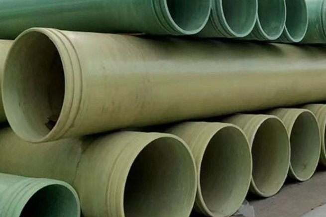
Seawater at ~35,000 ppm TDS, chlorinated to control biofouling and pumped at design velocity for fifty years is one of the most punishing duties a transmission pipeline can face. Carbon steel corrodes, lined steel lives and dies by its lining, and even 316L develops pitting and crevice attack in stagnant zones. This is why filament-wound FRP/GRP has become the default pipe material for DN 300–4000 in desalination plants worldwide — but "GRP" is a family of products, and picking the wrong resin, pressure class or stiffness class for a given duty is how good material ends up in bad service. This guide covers where FRP fits in a desal plant, resin and temperature ceilings, the applicable standards, pressure and surge design, buried installation, hydraulics, and the one service where standard GRP is the wrong answer.
1. Where FRP Pipe Sits in a Desalination Plant
A seawater reverse-osmosis (SWRO) plant is essentially a chain of low-pressure, high-flow services around one high-pressure service. FRP owns most of the chain:
- Intake and outfall. Large-bore lines (DN 800–4000) from open intakes or beach wells, and brine discharge outfalls — mostly gravity or low-head pumped. The largest diameters and the longest service lives sit here.
- Pretreatment. Filter manifolds, backwash lines and coagulant/chlorine dosing headers; pressures typically below 6 bar but heavily chlorinated water.
- Low-pressure transfer. Feed transfer to the high-pressure pump suction, interstage connections and permeate/product lines.
- Brine concentrate. The RO reject stream — still seawater-strength or saltier, often with residual antiscalant — routed to the outfall by gravity or booster pumps.
- Chemical dosing. Acid, antiscalant and hypochlorite lines in small diameters, usually FRP or thermoplastic.
Thermal plants (MED and MSF) add large cooling-water and condenser circuits, where the same material logic applies at moderately elevated temperatures (section 3). The single service FRP does not cover by default — the high-pressure membrane feed — is treated in section 8.
2. What Brine and Hypochlorite Do to Metals — and Not to FRP
The corrosion mechanism in desal service is electrochemical, and FRP simply does not participate in it. Chloride pitting and crevice corrosion require a metal surface and an electrolyte; a glass/resin composite has neither. Hot, oxygenated, chlorinated brine that forces a plant toward 904L or super-duplex metallurgy in steel is chemically routine for a vinyl-ester GRP pipe. Sodium hypochlorite dosing — typically 1–3 mg/L free residual for biofouling control — is a well-known accelerator of corrosion in metallic systems and simultaneously a routine service for FRP liners and pipe at those concentrations.
Biofouling behaves differently too. The smooth, low-surface-energy bore of a filament-wound GRP pipe (mean roughness around 0.05 mm) gives bacteria and molluscs less to anchor to than a corroding steel surface, so chlorination demand and headloss growth are lower. And because GRP is non-conductive, stray-current and galvanic effects disappear — no sacrificial anodes, no dissimilar-metal couples at valve chambers, no cathodic-protection system to commission and monitor for the life of the plant.
3. Resin Systems and Temperature Ceilings
Resin choice sets both the chemical resistance and the temperature ceiling of the pipe. The ceilings below are continuous-service guidance for pipe; always confirm against the resin supplier's chemical resistance and HDT data for the actual fluid chemistry:
| Resin system | Continuous service ceiling | Typical desalination role |
|---|---|---|
| Isophthalic polyester | ≈60–70 °C | Seawater intake, product water, ambient-temperature brine and backwash — the economical default |
| Vinyl ester | ≈90–100 °C (qualified systems to 110–120 °C per resin data) | Warm brine, MED condenser and evaporator circuits below ~70 °C, hypochlorite-rich duties, chemical dosing |
| Epoxy (GRE) | ≈110–150 °C with post-cure | High-pressure feed headers and hot, demanding services; the strength carrier where pressure, not chemistry, dominates |
Two derivative rules follow. First, pressure rating falls as temperature rises: once the fluid runs above about 35 °C, apply the supplier's derating table to the pressure class — a PN 16 line carrying 50 °C brine is not a PN 16 line any more. Second, match the liner to the chemistry, not the brochure: the corrosion liner is the working surface, and its specification (section 10) matters as much as the resin name on the datasheet.
4. Standards: Which One Applies Where
Desalination projects are tendered against a short list of pipe standards. Specifying the wrong one usually does not fail the pipe — it fails the inspection plan, because each standard carries its own qualification tests and tolerances:
| Standard | Scope | Where it fits in a desal plant |
|---|---|---|
| AWWA C950 | Glass-fibre pressure and non-pressure pipe, DN 25–4000, water service | The reference for municipal-scale intake, transmission and product lines in North America and many international tenders |
| ASTM D3517 | Fiberglass pressure pipe for water | Pumped seawater and product lines specified to ASTM |
| ASTM D3262 | Fiberglass gravity sewer and industrial waste pipe | Gravity outfalls, plant drains and non-pressure brine collection |
| ISO 10639 | Plastics piping — GRP pressure and non-pressure systems for water | International (non-US) tenders for pressure lines |
| ISO 10467 | Buried GRP pressure and gravity sewer systems | Buried brine gravity and pumped sewer lines |
| EN 1796 / EN 14364 | GRP pipe for water supply / for chemical and wastewater duties | European tenders; EN 14364 covers the chemical-service extras |
| ISO 14692 (+ API 15HR/15LR) | Glass-reinforced thermosetting pipe for petroleum and natural gas, incl. produced water and brine | Desal plants inside industrial/oilfield complexes; the basis for high-pressure GRE qualification |
5. Pressure Class, Surge and Temperature Derating
Large-diameter desalination lines are almost always low- to medium-pressure: PN 6 to PN 16 covers intake, pretreatment, product and most brine lines. Wall thickness cost rises steeply with pressure at large diameters, which is one reason high-pressure duties get their own solution (section 8).
Set the class in four steps. First, establish the maximum static working pressure from pump curves and elevation — without transients. Second, add surge: pumping stations and valve closures routinely generate 30–50% above working pressure, and the peak should be confirmed by transient analysis rather than assumed. GRP helps here — its elastic modulus gives pressure-wave speeds of roughly 300–600 m/s versus about 1,200 m/s in steel, so the instantaneous Joukowsky surge for the same Δv is materially lower — but GRP also tolerates less, so the analysis still has to be done. Third, derate for temperature above ~35 °C per section 3. Fourth, confirm the selected class carries the long-term (50-year) regression strength with the standard's safety factors — AWWA C950 and ISO 10639 both build this in through their design basis, which is why a certified class is worth more than a burst test.
6. Stiffness Class and Buried Installation
Buried GRP pipe is a soil-structure system: the pipe carries little vertical load by ring stiffness alone, relying on the surrounding embedment. Stiffness classes of SN 2500, SN 5000 and SN 10000 (per ISO 7685 / ASTM D2412) cover the usual range — SN 2500 for shallow, low-traffic cover, SN 10000 for deep trenches or heavy surface loads. The governing acceptance is long-term ring deflection, limited to 5% for GRP in ISO 10639 and C950-based designs; deflection beyond that risks liner cracking and joint rotation.
Select the class with the modified Iowa deflection calculation using the project's trench width, soil modulus, compaction regime, groundwater and traffic loads — not by habit. In parallel, deal with buoyancy: intake and outfall sections below the water table, and any line installed in a flooded trench, need concrete collars or deadman anchors sized for the empty-pipe condition, and a flotation check for the installation phase itself. Bedding and haunch compaction are where buried GRP is actually won or lost — a correctly specified SN 5000 pipe on uncompacted haunching under-performs a correctly bedded SN 2500.
7. Hydraulics and Fouling: What C = 150 Buys You
Filament-wound GRP has a Hazen-Williams coefficient around 150 and a Manning n around 0.009, and — critically — it keeps them. There is no corrosion to roughen the bore, so the friction factor at year 40 is the friction factor at commissioning. Projects that replace corroded steel (n ≈ 0.014 by mid-life) with GRP routinely recover on the order of 10–15% hydraulic capacity at the same diameter, or hit the same flow at a smaller diameter and lower pump head.
Fouling dynamics are equally favourable. Biofilm grows more slowly on the smooth bore, chlorination works more efficiently on a clean surface, and the headloss creep that plagues raw-seawater steel lines is largely absent. GRP also tolerates mechanical pigging without damage, so occasional cleaning is a cheap insurance. When sizing, it is still good practice to compute both the clean and the mildly-fouled condition and check pump duty against the second — the margin is small with GRP, but it should be a designed margin, not an assumed one.
8. The Exception: High-Pressure RO Feed Lines
The most expensive materials mistake in a desalination piping package is assuming that "GRP" covers every service. The membrane feed at 55–80 bar is a different engineering problem from a PN 16 brine line, and standard filament-wound polyester GRP is not the product for it.
High-pressure feed headers between the HP pumps, the energy-recovery devices and the membrane racks are served either by GRE — epoxy-glass pipe wound and qualified to ISO 14692 / API 15HR pressure classes — or by super-duplex stainless steel. GRE wins on corrosion freedom and weight at these pressures; super duplex wins where fitting complexity and branch geometry dominate. What both have in common is a qualified, tested pressure rating an order of magnitude above the PN 16 class — which standard water GRP does not offer, and should not be asked to fake by over-thickening walls.
9. Joints, Fittings and Outfall Details
Joint selection follows pressure and access. Double-bell elastomeric-gasket joints assemble fastest for buried intake and brine runs and accommodate ground movement, but unrestrained they rely on thrust blocks at bends and tees — or on restrained joint systems where thrust blocks are impractical. Butt-and-wrap laminated joints give a continuous, fully restrained pipeline and are the choice for above-ground runs and higher pressure; they demand trained laminators and proper cure before testing. Flanged connections belong at valve chambers, pump ties and equipment interfaces — with flat-face flanges, matched gaskets, stainless bolts and a torque sequence that treats the FRP flange as a precision component, not a steel one: over-torque crushes the flange face invisibly.
Marine outfalls add their own details: weight collars or concrete ballast for the empty-pipe condition, diffuser ports and risers laminated to the main line, a UV-stable outer surface for sections above water, and a float-and-sink installation plan agreed with the marine contractor. After assembly, every line — buried, above-ground or marine — is proven by hydrotest; the acceptance procedure and hold points are covered in our FRP pipe installation and pressure testing guide.
10. Specifying Checklist for Desalination Pipe Packages
- Fluid chemistry per line (salinity, temperature, oxidant residual) with the resin supplier's chemical resistance table attached to the spec
- Resin system selected against the temperature ceilings in section 3, with derating applied above 35 °C
- Pressure class from static + transient analysis, with surge confirmed by water-hammer study, not assumption
- Stiffness class from the modified Iowa calculation for the actual trench and traffic condition; 5% long-term deflection acceptance
- Corrosion liner specified: minimum 2.5 mm, glass content below ~30% by weight, verified by production-sample testing
- Joint types per section 9 with restraint and thrust design; laminator qualification for butt-and-wrap
- Buoyancy and anchorage design for buried and marine sections, including the installation-phase float case
- Potable-water certification (WRAS / NSF-ANSI 61) for product-water lines
- Factory hydrotest, stiffness and dimensional certificates; third-party inspection rights written into the PO
- Edge-sealing and repair kits supplied with the pipe for site fabrication
Related reading: our custom filament-wound FRP/GRP process pipes, the FRP pipe installation and pressure testing guide, trenchless GRP pipe installation, potable water approvals for FRP and filament winding angle design.
Need help selecting FRP products?
Our engineers answer technical questions free of charge.
Ask an Engineer on WhatsApp