
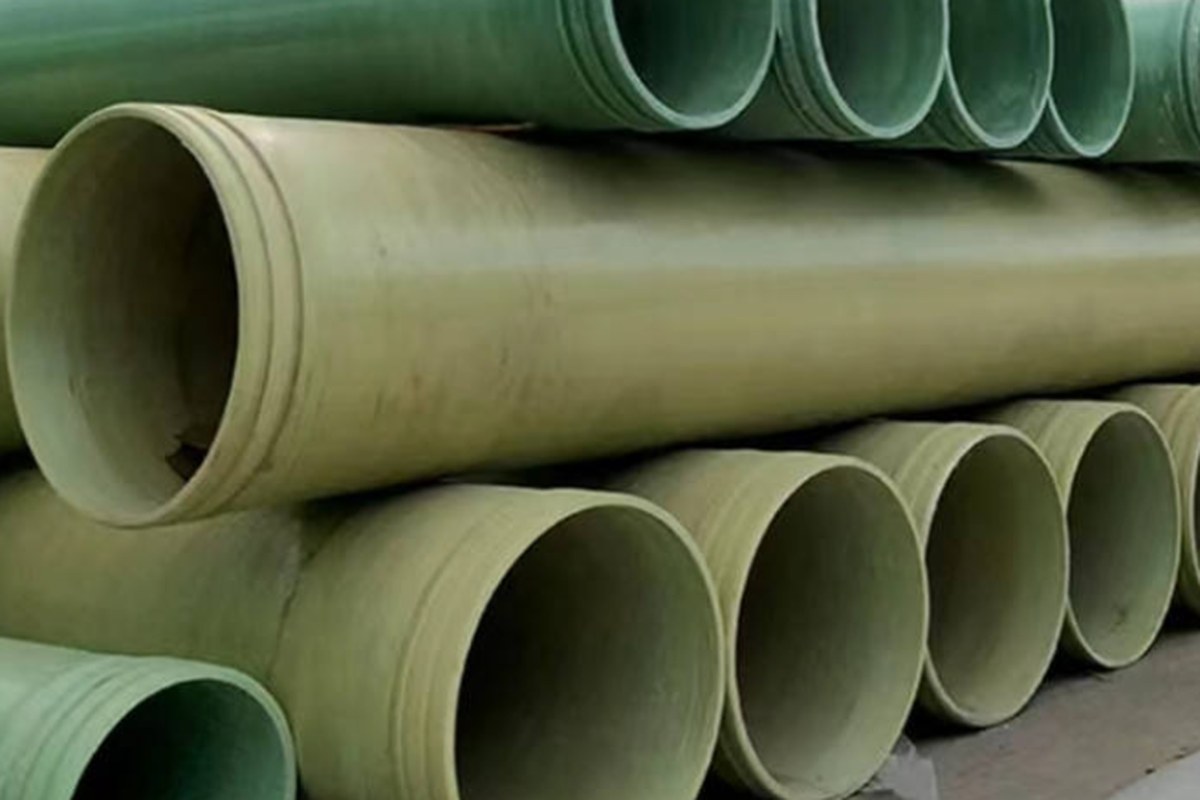
A GRP pipe that is correct for open-trench burial is not automatically correct for jacking. The material is the same, the resin is often the same, and the diameter may be identical - but a jacking pipe has to carry a few hundred tonnes of axial compression through a joint zone a few tens of millimetres long, survive being pushed through abrasive ground with no bedding under it, and still seal against groundwater once it stops moving. Those are different loads, and they call for a different pipe, a different joint and a different set of acceptance tests.
This guide covers the trenchless family of techniques as they apply to glass-reinforced plastics: pipe jacking, sliplining with continuous or discrete pipes, close-fit lining and segmental lining. It sets out which standard governs which technique, how the permissible jacking load is actually calculated from compressive strength, how to size a slipliner without destroying hydraulic capacity, what the site tolerances are, and how to write a specification that a fabricator cannot read ambiguously.
1. Where Trenchless GRP Wins, and Where It Does Not
Trenchless installation is not a premium version of open trenching. It is a different engineering problem with a different cost curve, and the crossover point is usually depth, obstruction and surface value rather than pipe diameter.
- Depth. Open trench cost rises roughly linearly with depth once shoring is required. Jacking cost is dominated by shaft construction, which is largely independent of the length between shafts. Two 6 m shafts and 80 m of drive can be cheaper than 80 m of 6 m deep shored trench before a single litre of groundwater is pumped.
- Surface value. Railway embankments, motorway carriageways, runways, tram lines and heritage streetscapes do not accept reinstatement as a cost item - they accept it as a permit problem. Crossing under a live railway is a routine jacking job and a very unpopular trench.
- Groundwater and contamination. In clean sand and gravel below the water table, a jacking drive with controlled face support removes the need for deep well dewatering and the settlement risk that comes with it. In contaminated ground it removes the spoil handling exercise entirely.
- Where it loses. Very short crossings, shallow depths in open farmland, hard rock without a roadheader or microtunnelling machine, and long drives through mixed face conditions with boulders. Jacking in boulder-strewn glacial till is a schedule risk that no material choice removes.
The material argument for GRP is separate and holds in both cases: a GRP pipe 4 m long and DN 800 weighs roughly a quarter of the equivalent concrete or steel pipe, which matters three times over in jacking - it reduces the jacking force needed to move the string, it lets a small crane handle the pipe at the shaft, and it avoids the point-load damage that heavy rigid pipes suffer at the leading edge.
2. Four Techniques, and the Standard That Governs Each
"Trenchless" covers techniques with completely different structural assumptions. Confusing them is the most common source of specification error, because a slipliner and a jacking pipe look like the same object in a photograph.
| Technique | How the pipe is installed | Structural role of the new pipe | Governing reference | Principal risk |
|---|---|---|---|---|
| Pipe jacking (new pipeline) | Segments pushed from a jacking shaft through the ground by a shield or machine head; spoil removed internally | Full structural pipe - carries soil load and jacking load | ISO 25780 (jackable GRP pipes); ISO 23856 (GRP product standard) | Exceeding permissible jacking load; joint misalignment on curves |
| Sliplining (rehabilitation) | A pipe of smaller diameter is pulled or pushed into the existing pipeline | Independent pipe in its own right; host pipe may be fully degraded | ISO 11296-2 (lining with continuous pipes) / ISO 11296-5 (discrete pipes) | Loss of hydraulic capacity; annular space and grouting design |
| Close-fit lining | Continuous liner deformed or folded to reduce its section, then expanded back to fit the host wall | Liner relies on host pipe for support against buckling | ISO 11296-3 (close-fit, PE and PVC-U systems) | Host pipe ovality; loss of the support condition the design assumed |
| Segmental / panel lining | Individual GRP segments or panels assembled inside the existing tunnel or culvert | Often designed as a self-supporting or partially composite structure | ISO 11296-8 (pipe segments); project-specific structural design | Grouting of the annulus and load transfer to the host structure |
The ISO 11296 series also matters for a reason that is easy to miss: it is a system standard, which means certain characteristics must be verified in the as-installed condition, after site processing, not only in the factory. A liner that meets every requirement on the delivery docket can still fail the specification if the installed condition is not tested. ISO 11295 sits alongside the series as the classification framework for renovation techniques, and ISO 11297 / ISO 11298 apply the same logic to pressure drainage and water supply networks respectively.
Practical rule: if the host pipe is being asked to carry structural load on behalf of the new pipe, you are in close-fit territory and the host pipe has to be inspected and rated. If the new GRP pipe is self-supporting and the host is only a void, you are sliplining, and the design is the same as a buried pipe plus an annular space.
3. The Product Standards: What ISO 25780 and ISO 23856 Actually Cover
ISO 25780 is the product standard that exists specifically for GRP pipes with flexible joints intended to be installed by jacking. It applies to glass-reinforced thermosetting plastics based on unsaturated polyester resin, in sizes from DN 100 to DN 4000, for water supply, irrigation, drainage or sewerage service, with or without pressure, at temperatures up to 50 °C. It specifies pipe characteristics and the test parameters for the reference test methods, and it adds requirements on joint design plus type test performance requirements for the joint as a function of declared nominal pressure and required joint deflection capability. That last clause is the reason a jacking pipe joint is not simply a push-fit joint with a thicker collar: it must be proven to seal while deflected, because a jacked pipeline is never perfectly straight.
ISO 23856 is the current main product standard for GRP pipes generally, and it merges and supersedes the older generation of regional standards (EN 1796, EN 14364, ISO 10467, ISO 10639). In practice a jacking pipe project cites both: ISO 23856 for the pipe as a pipe, ISO 25780 for the jacking-specific performance.
The test suite that sits behind those standards is where the engineering evidence lives. For jacking pipe the decisive test is the longitudinal compressive strength test - a prismatic specimen cut from the pipe wall is compressed along the pipe axis until it fails. That number, not the hoop tensile strength, sets the permissible jacking load.
| Property | Typical published value / basis | Why it matters for trenchless work |
|---|---|---|
| Ultimate axial compressive strength | About 85 MPa minimum for continuous filament wound and helical wound pipe; about 90 MPa for centrifugally cast | Direct input to the permissible jacking load calculation |
| Applied safety factor on declared jacking load | Commonly 3.5 in total (about 1.75 material factor combined with about 2.0 for eccentric loading); designers sometimes reduce to 3.0 or 2.5 on straight, well-lubricated drives | Determines the allowable load marked on the datasheet |
| Ring stiffness class (SN) | Jacking pipes are commonly specified at SN 80,000 N/m² and above, well above the SN 2,500-10,000 used for ordinary buried drainage | Resistance to buckling and ovalisation while unsupported during the drive |
| Maximum allowable joint deflection | Frequently quoted at 0.9° per joint for jacking pipe | Sets the minimum radius achievable with 2-4 m pipe lengths |
| Service temperature | -40 °C to +35 °C as standard on many jacking pipe ranges; higher on request | Sewer and stormwater service is comfortable; hot industrial effluent is not |
| Hydraulic roughness | Hazen-Williams C around 150, Manning n around 0.009 | Used to recompute capacity when a liner reduces the internal diameter |
| Thermal expansion | Approximately 24-30 × 10-6 mm/mm/°C | Movement is small but must be allowed for at shaft connections and thrust blocks |
4. Jacking Force: How the Permissible Load Is Calculated
The calculation is short and worth understanding, because it explains why a jacking pipe needs a thick wall and a calibrated joint zone even when the internal pressure is near zero.
- Take the minimum (not average) ultimate axial compressive strength from the test programme - commonly 85 MPa for filament wound pipe.
- Multiply by the minimum cross-sectional area of the pipe wall. That area is taken at the calibrated section at the joint zone, which is normally the thinnest and most highly loaded part of the pipe, not the barrel.
- Divide by the safety factor, typically 3.5 in total, and declare the result as the permissible maximum jacking force on the datasheet.
Worked example - DN 800 jacking pipe, 20 mm wall. Nominal outside diameter 840 mm, inside diameter 800 mm. Wall cross-sectional area = π/4 × (8402 - 8002) = 51,500 mm². Taking the joint-zone calibrated section at about 92% of that area gives 47,400 mm². Ultimate capacity = 85 N/mm² × 47,400 mm² = 4,029 kN. Dividing by 3.5 gives a permissible maximum jacking force of about 1,150 kN, roughly 117 tonnes.
That figure then has to be compared with the force the drive will actually demand. For a lubricated drive the useful estimate is skin friction, which for GRP pipe in most soils with a bentonite or polymer lubricant sits in the range of roughly 3-10 kN per square metre of pipe surface, plus any face resistance. For the same DN 800 pipe, external circumference is 2.64 m; at 5 kN/m² unit friction that is about 13.2 kN of friction per metre of drive. Against a 1,150 kN allowance, a single straight drive can theoretically reach roughly 85-90 m before the jacking load alone consumes the whole permissible force - which is why practical drive lengths are set shorter, and why interjack stations become necessary beyond 60-100 m depending on ground.
Design against the jacking force, not against the pipe that fits the hole. If a project needs 150 m in one drive, either accept intermediate jacking stations, increase the wall thickness, or choose a machine configuration that reduces face load - the permissible force is fixed by the pipe, not by the rig.
5. Pipe Geometry, Wall Thickness and the Joint Zone
Three geometric details decide whether a jacking pipe survives the drive:
- Wall thickness and squareness. The whole jacking force passes through the annulus at the ends. Squareness tolerance at the pipe ends is what prevents point loading: if the end face is not flat and parallel, the load concentrates on one side of the collar and the compressive failure happens at a fraction of the calculated load. This is why jacking pipes are machined or ground at the ends and why the fabricator's dimensional report is part of the acceptance pack.
- The joint. GRP jacking joints are typically a socket-and-spigot or a collar arrangement with a compressible packing or a steel/GRP load ring to transmit the jacking load without crushing the elastomeric seal. The seal must remain watertight at the design joint deflection, which is what ISO 25780's joint deflection type tests exist to prove.
- Liner and pipe length. Short pipes at the shaft ends are normal practice: a length of one pipe diameter up to less than 2 m is commonly installed at the jacking and receiving pits to help alignment and to allow the joint to be deflected through the shaft entry. Curves are made by deflecting joints within their allowance, not by bending the pipe.
Wall thickness is not a direct pressure calculation in a jacking pipe. It is the result of three checks: jacking compressive stress including eccentricity, external soil and traffic load with the required buckling safety factor, and ring stiffness class for a pipe that is unsupported by bedding during the drive. On top of that sits the pressure rating for the service the pipeline will eventually see - PN 6 and PN 10 are common requirements, with factory hydrostatic tests run well above the nominal rating.
6. Sliplining: What Diameter Costs You, and How to Grout the Annulus
Sliplining is where hydraulic engineers and structural engineers most often disagree, because the structural engineer wants wall thickness and the hydraulic engineer wants a diameter. The trade is quantified by the capacity loss, which grows faster than the diameter loss.
For full-bore gravity flow at the same gradient, capacity scales approximately with diameter to the power 2.67. A diameter reduction of roughly 11% costs roughly 27% of the flow capacity - a result that surprises almost every project the first time it is computed.
| Host pipe nominal ID | GRP liner wall | Liner OD / ID | Annular clearance (on diameter) | Approximate capacity retained at the same gradient |
|---|---|---|---|---|
| DN 400 (400 mm) | 8 mm | 380 / 364 mm | 20 mm | About 79% |
| DN 400 (400 mm) | 10 mm | 375 / 355 mm | 25 mm | About 73% |
| DN 600 (600 mm) | 10 mm | 575 / 555 mm | 25 mm | About 82% |
| DN 800 (800 mm) | 12 mm | 770 / 746 mm | 30 mm | About 84% |
The numbers above assume a clean, round host pipe. Three qualifications change them in practice:
- Clearance. Jointed GRP sections need enough annular space to negotiate the host pipe's own joints, offsets and any root intrusion. A working clearance of 25-50 mm on diameter is typical; below that, pushing a jointed liner through a deteriorated sewer becomes a jamming exercise.
- Self-cleansing velocity. A reduced diameter is not automatically a problem, but the re-computed velocity at low flow must still achieve self-cleansing. In flat sewers the loss of capacity shows up first as sediment deposition, not as surcharge - and deposition is what kills a lined sewer in a decade.
- Annular grouting. For a self-supporting liner, grout is not a structural requirement; it is a stabilisation and load-transfer measure. Grouting the annulus stops the liner floating or creeping, prevents migration of groundwater along the outside of the liner and eliminates voids that would otherwise become corrosion cells. Where the design relies on the host pipe for buckling support - the close-fit case - grout and contact are structural, and the design must say so explicitly.
Where capacity loss is unacceptable, the alternatives are to upsize upstream, to accept partial renewal, or to change technique: segmental GRP liners and spiral-wound liners exist precisely to keep more of the original diameter, at the price of a more complex structural argument. For pressure mains being rehabilitated, the design also has to account for the fact that the liner now carries the working pressure and any surge independently.
7. Soil Loads, Buckling and the Combined Stress Check
Jacking pipe spends part of its life with no bedding beneath it and no backfill around it, and the rest of its life with the full soil prism plus traffic load above it. Both states have to be checked, and the checks are not limited to stress.
- Ring deflection. Vertical deflection under earth load must stay within the allowable for the pipe's strain class, typically with a safety factor applied to the long-term ring bending strain (about 0.8% is a common long-term figure, with the short-term ring bending strength far higher).
- Buckling. The external pressure at which a buried flexible pipe buckles depends on the pipe's ring stiffness, the soil's modulus and the ovality of the installed pipe. Jacking pipe with SN 80,000 N/m² and above is far outside the range where buckling governs in ordinary ground - but it also costs more, so overspecifying stiffness to avoid a calculation is an expensive habit.
- Combined axial compression plus ring bending. During the drive, the wall simultaneously carries longitudinal compression and ring bending from the surrounding ground reaction. The combined stress check, with its own safety factor, is usually the governing one for a long drive in stiff ground - not the simple compressive strength divided by 3.5.
- Live load. Road, rail and aircraft loading above the drive is a standard input. The methodology for jacked pipelines under these conditions, including the effects of the annular gap and the grouting regime, is set out in the German DWA-A 161 body of practice, which is widely used internationally for this purpose.
The soil you are jacking through is a design input, not site information. Unit friction, face resistance, the presence of boulders and the groundwater regime all change the drive, and a specification that fixes the pipe class without the geotechnical report is a specification that will be renegotiated on site.
8. Site Execution: Lubrication, Interjacks, Guidance and Tolerance
The material tolerates the method if the method is disciplined. The site sequence that keeps a GRP drive inside its permissible load looks like this:
- Verify the shaft. Jacking thrust must react into a designed thrust block or the shaft lining, and the reaction must be checked against the shaft's own capacity. A thrust wall that moves takes the alignment with it.
- Set the machine and guidance. A laser target, and where required a guidance system with articulation, allows deviation to be corrected continuously. Steering a GRP pipe relies on joint deflection, so the permissible joint angle is effectively the steering limit.
- Lubricate from the first metre. Bentonite or polymer lubricant injected through ports in the pipe wall reduces skin friction, and it must start with the first pipe rather than being introduced when friction becomes a problem. Once the string is tight in the ground, a lubricant injection port can be as hard to reach as the front of the drive.
- Monitor the jacking load continuously. The jacking force curve should rise slowly and smoothly. A sudden increase means obstruction, misalignment, or loss of lubrication, and continuing to push converts a recoverable delay into a crushed pipe.
- Fit interjack stations before they are needed. For long or high-friction drives, an intermediate jacking station divides the string into independently pushed sections. The decision is a design decision made before the drive, not a rescue measure during it.
- Arrest settlement and record it. Monitoring points on the surface above the drive line, taken before and during jacking, are what allow the contractor to prove no damage was caused - which matters more after a rail or highway crossing than the drive itself.
- Handle with the right equipment. GRP pipe is light, which is an advantage, but it is also elastic and relatively thin walled: slings, spreader beams and end protection prevent the impact and point-load damage that shows up later as a crack at the joint.
9. Acceptance Testing and the Failure Modes to Design Out
Acceptance for a jacked or sliplined GRP pipeline has three layers: the pipe as delivered, the joints as installed, and the pipeline as a system.
| Failure mode | Root cause | Prevention |
|---|---|---|
| Longitudinal crushing at the pipe end | Jacking load above the permissible value; non-square end face concentrating load on one side | Declared permissible jacking force on the datasheet, load monitoring with a stop limit, dimensional report on end squareness |
| Joint leak after completion | Joint deflected beyond its tested allowance, or packing damaged during the drive | Type test evidence for the joint at the design deflection; steering limits enforced by survey |
| Ovalisation or local buckling during the drive | Excessive ground reaction with unsupported barrel, or over-steering | SN class matched to the geotechnical report; combined stress check |
| Reduced hydraulic capacity after sliplining | Diameter loss not re-computed; self-cleansing velocity not checked | Capacity calculation using the installed internal diameter, and a low-flow velocity check |
| Groundwater migration along the liner | Annulus left ungrouted, or grouted with voids | Specified annular grout with a placement method and volume reconciliation |
| Abrasion of the pipe wall by the surrounding ground | Friction against aggressive spoil, especially in sand and gravel, over long drives | Abrasion allowance in wall thickness; lubricant programme; external coating where warranted |
| Seepage through a transverse crack after installation | Impact damage during handling, or point loading in a poor shaft | Sling-protected handling, visual inspection of every pipe on delivery, repair procedure agreed in advance |
The system-level tests are the familiar ones: a hydrostatic or low-pressure air test on sewer sections, deflection measurement of the installed pipeline, and a closed-circuit television survey of the finished bore. CCTV on a lined sewer is not a formality - it is the only record of whether the liner was damaged, whether the joints are aligned and whether the annular space was fully grouted. For pressure pipelines, the field pressure test procedure in our FRP pipe installation and pressure testing guide applies after the drive, with the additional requirement that the test pressure does not exceed the rating of the thrust restraint at the shaft connections.
10. Specification and Procurement Checklist
| Item | What to put in the specification |
|---|---|
| Technique and structural role | State jacking, sliplining, close-fit or segmental, and say explicitly whether the new pipe is self-supporting or relies on the host |
| Product standard | ISO 25780 for jacking pipe; ISO 23856 as the GRP product standard; ISO 11296-Part 2, 3, 5 or 8 for renovation techniques |
| Size, wall thickness and SN class | DN, wall thickness with tolerance, and ring stiffness class; plus the maximum permissible jacking force |
| Pressure class | PN rating, factory hydrostatic test pressure and duration, and the site test pressure |
| Joint performance | Type test evidence at the required deflection angle; maximum allowable joint deflection and axial displacement per joint |
| Geotechnical design basis | Unit skin friction assumption, face load, groundwater, cover depth and live load, with the design methodology named |
| Lubrication and thrust | Lubricant type and injection point arrangement; thrust block capacity; interjack station provision and its trigger load |
| Delivered condition | End squareness tolerance, dimensional report, visual acceptance for cracks and impact damage, and repair procedure |
| Installed condition verification | Deflection measurement, joint alignment survey, CCTV record, annulus grout volume reconciliation, pressure or air test |
| Cost drivers to state up front | Drive length between shafts, required joint deflection for the alignment, whether interjacks are included, and the soil class |
HuanGang manufactures filament-wound GRP pipe for pressure and gravity service, including pipe sizes and wall builds intended for trenchless work - the filament winding process is what makes the high axial compressive strength and repeatable wall thickness that jacking depends on. Core references for this subject are the filament-wound GRP process pipe range, the FRP pressure pipe series for pumped and pressure mains, and the FRP water pipe for supply and drainage duty. Send us the host or new pipeline diameter, the drive length, the soil description, the required pressure class and the deflection the alignment demands, and we will come back with a wall thickness, SN class and permissible jacking force for the pipe you actually need. For the diameter and wall thickness decision itself, see how to select FRP pipe diameter and wall thickness; for the specification paperwork, see our GRP pipe specification and selection guide; and for above-ground support and spacing see FRP pipe support spacing and hanger design.
Need help selecting FRP products?
Our engineers answer technical questions free of charge.
Ask an Engineer on WhatsApp