
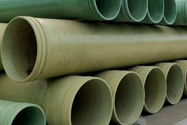
The three gases of the energy transition — hydrogen, ammonia and carbon dioxide — arrive at the pipe with three completely different sets of demands, and the mistake most common in early project specifications is to treat them as one problem called "corrosive gas". Hydrogen is the smallest molecule in industrial service, so permeation rather than corrosion governs the barrier; ammonia is a moderately strong base whose liquid form is either perfectly suited to FRP or completely unsuited to it depending on whether it carries water; carbon dioxide is dense-phase, invisible as a liquid, and expands violently enough when a line depressurises that it damages elastomers and thermoplastics that show no problem at all in a static immersion test. All three are now routinely proposed for glass-reinforced pipe, and the technical basis for doing so has moved quickly: reinforced thermosetting resin piping was formally written into the ASME hydrogen code only in 2016, and the international composite qualification framework — ISO 23936-4 — was not published until 2024.
This guide is written for the engineer writing the material requisition, not for a chemistry lecture. It covers where FRP is permitted in these services and where it is not, how much gas actually leaves through the pipe wall and how to calculate it, which liner and resin families survive long contact, what the qualification test programme has to demonstrate, and which field tests and earthing rules apply. Every number quoted below is traceable to a published code, standard or test programme, and the worked examples were run as calculations rather than estimated.
1. Three Gases, Three Different Failure Mechanisms
Start by separating the mechanisms, because each one eliminates a different part of the usual FRP specification.
| Gas | Property that drives the design | Consequence for a composite line |
|---|---|---|
| Hydrogen (H₂) | Kinetic diameter 2.89 Å — smaller than methane (3.80 Å) — and a wide flammability range | Permeation through the liner is the dominant gas-loss path; hydrogen embrittlement is a steel problem and does not apply to the laminate. Fire behaviour and electrostatic ignition become the governing safety issues, which is why the code restricts FRP to buried installation. |
| Ammonia (NH₃) | Strong base (pH 10–12 in commercial aqueous solution); vapour pressure above atmospheric; anhydrous liquid boils at −33 °C | Aqueous ammonia is an FRP application with a restricted resin list. Anhydrous ammonia is not an FRP application at all. Vacuum collapse on cooling is a real operating hazard, and FRP vessels are difficult to design for vacuum. |
| Carbon dioxide (CO₂) | Dense phase above the critical point; very high solubility in polymers; large Joule–Thomson cooling on release | Rapid decompression blistering is the classic failure mode and is explicitly excluded from the newest ISO composite standard, so it must be qualified separately. Mass loss through a polymer barrier is far higher than for hydrogen at the same permeability. |
Two of these three gases reward FRP enormously. A glass-reinforced line has no internal corrosion allowance to consume, cannot suffer hydrogen-assisted cracking, and does not need the internal coating or inhibitor programme that dry-gas steel lines depend on. The third mechanism — decompression damage — is what the qualification programme exists to exclude.
2. Service Limits: Where FRP Is Permitted and Where It Is Not
Composite piping for hydrogen is not a generic substitution; it is a codified, bounded application. ASME B31.12 ("Hydrogen Piping and Pipelines") did not originally allow polymer piping, and the route into the code was ASME B31 Case 200, "Composite Piping for Hydrogen Service", approved by the B31 Standards Committee on 31 October 2016 after a multi-year test programme by the US national laboratories.
| Service | Governing document set | Position of FRP / GRP |
|---|---|---|
| Gaseous hydrogen, transmission and distribution | ASME B31.12 plus B31 Case 200 | Permitted up to 6 in (DN 150) nominal diameter and 2,500 psi (about 172 bar) design pressure, with a 50-year design life. Installation is restricted to below ground because the plastic pressure boundary is combustible in a fire. |
| Hydrogen blending into existing networks | National gas network rules plus B31.12 where applicable | Composite spoolable line pipe is the practical option for relining and for narrow rights of way, but the blend, the pressure cycle count and the fire exposure have to be declared before a code-compliant rating is issued. |
| Aqueous ammonia (aqua ammonia), typically 10–30 % | ASME NM.2 / ASTM D2996 / D3299, plus resin supplier chemical resistance data | Accepted with premium alkaline-resistant resin systems only. Standard isophthalic and terephthalic polyesters are excluded by the material selection literature for ammonia service. |
| Anhydrous ammonia (liquid, −33 °C) | Not an FRP application | The industry material selection guidance is explicit: anhydrous ammonia should not be used with FRP other than in the preparation of dilute ammonium hydroxide solutions. Use steel, and note that a site holding more than 50 t of anhydrous ammonia falls into the lower tier of Seveso III (50 t / 200 t thresholds). |
| Carbon dioxide, dense phase or supercritical | ISO 27913 and DNV-RP-F104 govern the steel systems; ISO 23936-4 covers composite qualification | No dedicated FRP code exists. Acceptance is by project-specific qualification, and the reference documents for fracture control (16–36 in diameter, 10–26 mm wall, X60–X65 submerged-arc pipe) describe steel and are not transferable to a laminate. |
| Wet carbon dioxide with oxygen and sulphur impurities | Project specification plus ISO 23936-4 test programme | Feasible, but the corrosion barrier must be selected for the acidic, oxidising mixture, not for "CO₂". Impurity limits written for steel systems exist for other reasons and cannot simply be relaxed because the pipe is plastic. |
Rule of thumb: if the service is hydrogen, ask for the code case and the underground restriction first; if it is ammonia, ask whether the stream is aqueous; if it is CO₂, ask for the decompression qualification. Those three questions eliminate most unsuitable enquiries before any structural calculation is done.
3. Permeation Is the Leak Path That Sets the Barrier Thickness
In a composite pressure line the structural laminate is not the barrier. The inner polymer liner is: in the hydrogen code case, the polyethylene liner is defined as the primary barrier for leakage control, while the glass-reinforced layer carries the hoop load and the outer polymer jacket only protects the laminate during handling and installation. That division matters because it means gas loss through the wall is governed by a thermoplastic permeation coefficient, not by the laminate's strength.
Permeation through a pipe wall is estimated from the permeability coefficient of the barrier material, the partial-pressure difference, and the pipe geometry:
- Volumetric rate: QV = PC × (SDR − 1) × π × L × Δp / 1000, in ml per day, where PC is in ml·mm/(m²·bar·day), SDR is the standard dimension ratio (outer diameter ÷ wall thickness), L is length in metres and Δp is the partial-pressure difference in bar.
- Mass rate: Qm = QV × ρ / 10⁶, in kg per day, with ρ the gas density in kg/m³ at the reference conditions.
- The governing variables are therefore liner thickness and temperature. Permeation falls in proportion to liner thickness and rises steeply with temperature — for polyethylene in hydrogen service the published range moves from 55–89 ml·mm/(m²·bar·day) at 8 °C to 299–523 at 40 °C.
| Barrier material | Hydrogen PC | Methane PC | Carbon dioxide PC | Notes |
|---|---|---|---|---|
| PE 80 / PE 100 / PE 100-RC at 8 °C | 55–89 | 6–9 | not reported | Units are ml·mm/(m²·bar·day). Polyethylene is the liner material named in the hydrogen code case; PE 100-RC measured 126.8 for hydrogen against 56 for methane in independent tests, and pipes exposed to 100 % hydrogen for 1,000 hours at 2 bar showed no significant chemical or mechanical change. |
| PE 80 / PE 100 / PE 100-RC at 20–25 °C | 108–193 | 10–37 | 136–279 | |
| PE 80 / PE 100 / PE 100-RC at 40 °C | 299–523 | 98–165 | not reported | |
| PA 11 / PA 12 at 20–25 °C | 51.3–95.8 | 0.38–5.8 | 27.1–58.3 | Polyamide is a lower-permeation barrier than polyethylene for all three gases, at a cost in moisture sensitivity and impact behaviour. |
| PVC-U / PVC-HI / PVC-O at 20–25 °C | 79.7–181.3 | 0.5–3.7 | 7–10.4 | Included for comparison; not a pressure-boundary liner for high-pressure gas service. |
One structural point is worth stating explicitly because it is counter-intuitive: carbon dioxide permeates faster than hydrogen through polyethylene at ambient temperature even though the CO₂ molecule is larger (kinetic diameter about 3.30 Å against 2.89 Å). Permeation is a solubility-driven process as much as a size-driven one, and CO₂ has high solubility in polyolefins. Sizing a liner from molecular size alone gives the wrong answer.
4. Worked Permeation Rates for a Realistic Line
The following calculation is for a DN 150 (6 in) spoolable composite line with a 6 mm polyethylene liner (SDR 25), one kilometre long, using mid-range coefficients. It is deliberately a liner-only calculation, so it is an upper bound: the structural glass/epoxy layer and any outer jacket add resistance, and they are not credited here.
| Service | Line pressure | Volumetric loss per km | Mass loss per km | Loss as fraction of throughput |
|---|---|---|---|---|
| Hydrogen | 10 bar | 0.113 m³/day | 0.010 kg/day (3.7 kg/year) | — |
| 50 bar | 0.565 m³/day | 0.051 kg/day (18.6 kg/year) | — | |
| 100 bar | 1.131 m³/day | 0.102 kg/day (37.1 kg/year) | about 0.001 % of a 10 t/day flow | |
| Carbon dioxide | 10 bar | 0.151 m³/day | 0.298 kg/day (109 kg/year) | — |
| 50 bar | 0.754 m³/day | 1.491 kg/day (544 kg/year) | — | |
| 100 bar | 1.508 m³/day | 2.981 kg/day (1,088 kg/year) | about 0.0003 % of a 1,000 t/day flow |
Read the two halves of that table against each other. At the same volumetric loss rate — 1.5 m³/day — the mass lost as hydrogen is 0.14 kg/day while the mass lost as carbon dioxide is 2.98 kg/day, a factor of 22 that comes entirely from gas density. For hydrogen, permeation is a safety-and-gas-detection issue, not an economic one: 37 kg per kilometre per year is negligible against the throughput of a transmission line. For a dense-phase CO₂ line in a carbon-capture scheme the same calculation becomes a mass-balance, emission-accounting and, in some jurisdictions, a reporting issue, and it is worth a dedicated review rather than a line in the datasheet.
Two sanity checks on the model are worth recording. First, measured leak rates on commercial spoolable composite specimens of 0.9–2.7 m at 100 bar hydrogen were reported as being at or below the instrument detection limit (around −5 × 10⁻⁴ mol/h) against a predicted permeation rate of 8 × 10⁻³ to 2.4 × 10⁻² mol/h, which is consistent with permeation being the dominant path rather than connector leakage. Second, applying the same formula to a 1 m spool reproduces the same order of magnitude as that published prediction (2.1 × 10⁻³ mol/h). The model is therefore adequate for sizing, but it should be treated as an estimate for gas-detection and ventilation design, not as a certified leak rate.
5. Liner and Corrosion Barrier Selection
The liner has one job — be continuous, stay bonded or anchored, and resist the fluid — and it should not be selected on temperature alone. Practical guidance:
- Hydrogen: high-density polyethylene is the default, and the code-case product form is an HDPE liner inside a glass/epoxy structural layer with an outer polyethylene jacket. Polyamide liners show roughly half the hydrogen permeability of polyethylene and are worth evaluating where gas loss or detection thresholds are tight, provided moisture and impact behaviour are acceptable.
- Carbon dioxide: the barrier must tolerate the acidic mixture that forms when any water is present, so vinyl ester or a thermoplastic liner such as PVDF or ECTFE is the normal direction once impurities are declared. Where the CO₂ is dry and clean, thinner liners are defensible; where it is wet, the barrier chemistry, not the coefficient, decides.
- Aqueous ammonia: premium alkaline-resistant resin systems are required. Vinyl ester and the alkaline-resistant bisphenol-A based chemistries are the mainstream answer; standard isophthalic and terephthalic polyesters are excluded for ammonia service in the standard FRP material selection guidance.
- Interface rule: a liner is only a barrier if it is continuous through the joints. On spoolable lines the liner is part of the factory-made pipe and the connection is a mechanical end fitting; on site-laminated equipment the barrier is rebuilt as a resin-rich corrosion layer with a specified glass content and thickness, and that layer is what the qualification test must interrogate.
6. The Structural Laminate and the ISO 23936-4 Qualification Framework
Since 2024 there is a single international test framework for continuous-fibre composites in oil, gas and lower-carbon service. ISO 23936-4:2024 covers flat laminate and tubular specimens and sets out four levels of evaluation, from an unaged baseline to long-term life prediction.
| Level | Purpose | Duration and conditions | Test media |
|---|---|---|---|
| Level 1 | Baseline material characterisation, unaged, dry, room temperature | None | Tensile to ISO 527-4/5 or ASTM D3039, compression to ISO 14126, in-plane shear to ISO 14129, interlaminar shear to ISO 14130, Mode I / Mode II fracture toughness to ISO 15024 / 15114, hoop tensile to ASTM D2290 for tubular products |
| Level 2 | Short-term stability at the upper service temperature | 2, 7, 14 and 28 days, free exposure | Air, 30 g/kg KCl brine, an aromatic mixture of 70 % heptane / 20 % cyclohexane / 10 % toluene, or project-specific fluids |
| Level 3 | Accelerated ageing in the multiphase environment | Up to 56 days at three temperatures at least 10 °C apart | H₂S / CO₂ / CH₄ multiphase mixture |
| Level 4 | Long-term life estimation | At least 180 days, three temperatures | As Level 3, with pass/fail thresholds set by the designer |
Two features of that framework should shape a purchase specification. First, the standard deliberately does not prescribe a single acceptance threshold at Levels 2 to 4: the user defines the property change that constitutes failure, which means the requisition has to state it. Second, blistering caused by rapid gas decompression is outside the scope, as are coatings and short-fibre or particulate-filled composites — so an ISO 23936-4 report alone does not close out decompression risk.
For hydrogen service the code case adds laminate-specific controls that are easy to leave out of a Chinese or European quotation: acceptable resin systems are epoxy, polyester or vinyl ester; acceptable reinforcement is Type E, Type E-CR or Type S glass; the laminate must retain a minimum interlaminar shear strength of 14 MPa (2,000 psi) tested to ASTM D2344 after a 24-hour water boil, which verifies that a buried, moisture-exposed pipe will not lose load transfer between layers over a long service cycle; cure is verified by Barcol hardness or an equivalent such as differential scanning calorimetry; and all material must be traceable to an individual laminate lot and recorded in the manufacturer's construction records. Metallic load-bearing parts of joints must satisfy the metallic rules of B31.12, which means the end fitting is a code component in its own right.
7. Rapid Decompression: the Failure Mode the Standards Exclude
When a polymer has absorbed gas under pressure and the pressure is released quickly, the dissolved gas expands inside the material and can crack or blister it. The industry test method is NORSOK M-710 Annex B, now reproduced as ISO 23936-2: a 5.33 mm section O-ring is held at 100 °C and 15 MPa in a 90/10 methane/CO₂ mixture, cycled eight times with decompression at 20–40 bar/min and a one-hour dwell, then cut into sections and rated 0 to 5. Ratings of 4 and 5 are failures; only 0 to 3 pass, and a 0000 rating means no visible internal damage.
Published test data shows why a composite specification for CO₂ has to be conservative:
| Variable | Test condition | Result |
|---|---|---|
| Decompression rate | FFKM seal, 200 bar, 200 °C, CO₂/N₂ 10/90 | 20 bar/min: 100 % pass; 60 bar/min: 100 % pass; 120 bar/min: 90 %; 180 bar/min: 83 % |
| Gas identity | 200 bar, 200 °C, 120 bar/min | 100 % CO₂: 50 % pass; 100 % helium: 100 %; 100 % nitrogen: 100 % |
| CO₂ content | At 150 °C versus 200 °C | At 150 °C all concentrations passed; at 200 °C, 0 % CO₂: 100 % pass, 10 %: 89 %, 20 %: 89 %, 50 %: 66 % |
The engineering conclusion is not that FRP fails in CO₂. It is that the decompression specification has to be written from the actual operating envelope — maximum temperature, maximum pressure, and above all the depressurisation rate that will be achieved in an upset or maintenance blowdown. A line depressurised slowly passes materials that fail at 180 bar/min. NACE TM0192 and TM0297 offer alternative CO₂-specific regimes at room temperature and at 50–230 °C, and they grade on a 1–4 scale, so a supplier's report has to be read for which method was used and what the pass criterion was.
8. Joints, End Fittings and Field Testing
The pressure boundary of a spoolable composite line changes nature at the end fitting, and this is where field failures concentrate. Practical points:
- Mechanical end fittings, not field lamination, are the norm for spoolable pipe: the composite is compressed onto a metallic insert or crimped connector, so the fitting design is qualified by burst and leak testing for the specific pipe. In the code-case programme, two burst tests on dry-wrapped thermoplastic pipe returned 3,670 and 3,870 psi with a rated 50-year pressure of 580 psi, and crimped connectors met the leak acceptance criterion.
- Field pressure testing follows ASME NM.2 practice for glass-fibre-reinforced thermosetting-resin piping systems: test at 1.33 to 1.5 times design pressure, hold for a minimum of 10 minutes, and examine every joint for leakage. On long composite systems it is normal to test in sections so that the test pressure at the low end of an elevation change does not exceed the fitting rating.
- Cure and hardness verification belongs in the field records as well as the factory ones. Barcol readings on a laminate that has been left in cold weather before jointing are the cheapest early warning of an under-cured bond.
- Leak detection on hydrogen is a scheduled activity, not a response to smell. For distribution systems, B31.12 practice requires annual leakage surveys in principal business districts and intervals no longer than 5 years for odourised and 12 months for non-odorised hydrogen outside those areas. Since permeation is continuous and diffuse, surveys should target fittings, valve stems and flanges rather than the pipe body.
- Vacuum and drainage design matters more than it does in steel. A composite line that can be drained down, blown clear and left empty avoids most long-term barrier problems; a line that holds a stagnant wet heel at a low point will attack its own corrosion barrier.
9. Fire, Static Electricity and the Underground Rule
Plastic piping is combustible, and the codes treat that as a first-order hazard in flammable-gas service. The hydrogen code case resolves it by restricting FRP to underground installation, where a fire cannot be fed by the pipe itself and the surrounding soil limits oxygen. Above-ground composite sections, if they are permitted at all by the authority having jurisdiction, need fire protection and separation that steel does not.
The second safety issue specific to composites is static. FRP is an insulator, so a charge generated by flowing dry gas cannot drain through the wall. IEC TS 60079-32-1 classifies pipe and pipe-assembly end-to-end resistance in three bands, and the middle one is the design target:
| Resistance band | End-to-end resistance | Suitability for gas service |
|---|---|---|
| Conductive | R < 1 kΩ | Drains charge, but stray-current corrosion and galvanic issues become a concern |
| Dissipative | 1 kΩ ≤ R < 1 MΩ | The recommended band for pipe and pipe assemblies: charge drains without a fully conductive path |
| Insulating | R ≥ 1 MΩ | Not suitable where a flammable atmosphere can be present, because charge cannot be removed safely |
- Specify an antistatic or conductive-lined FRP pipe where the fluid is flammable, and test the resistance of the delivered pipe rather than accepting a resin description.
- Limit fill velocity to about 1 m/s until the fill connection is submerged by at least two pipe diameters, which is the single most effective control against charge generation in non-conductive liquids and is also the standard guidance for the liquid-ammonia and solvent cases.
- Allow a relaxation time of 30 to 60 seconds after flow stops before gauging, sampling or breaking a joint.
- Bond and earth all metallic components — valves, filters, end fittings, supports — and treat any bonded metal path as needing a resistance in the order of 10 Ω, while dissipative objects are checked against the 1 MΩ limit. A conductive liner with a broken earth bond is worse than a documented insulating one, because everyone assumes it is safe.
10. Carbon Dioxide Service: What Actually Governs
CO₂ is the service where "FRP is corrosion-free" is true and still not sufficient as an argument.
- Water is the controlling impurity. Dense-phase CO₂ carrying free water forms carbonic acid and, with oxygen, sulphur and nitrogen oxides from capture processes, becomes an aggressive acidic mixture. Industry practice for CO₂ transport sets water at or below about 0.02 % by mass with a dew point margin of roughly 5 °C below the pipeline operating temperature. Those limits exist to protect steel, but the impurity envelope still has to be declared for a composite line because the corrosion barrier sees the same mixture.
- Decompression qualification is mandatory in practice, for the reasons set out in section 7, and it must be done at the maximum operating temperature rather than at ambient.
- Mass loss is not negligible. At 100 bar a one-kilometre DN 150 liner releases roughly 3 kg of CO₂ per day, about 1.1 t per year, which is two orders of magnitude more mass than the equivalent hydrogen loss from the same wall.
- Fracture control rules do not transfer. ISO 27913 and DNV-RP-F104 provide the running-fracture and minimum-wall-thickness framework for steel CO₂ pipelines; their calibrated range is large-diameter, thick-wall, high-grade line pipe. A laminate has no ductile-to-brittle transition and no Charpy arrest requirement, so the composite case must be argued from stress rupture and fatigue data instead — for which ASTM D2992 remains the standard basis.
11. Ammonia Service: Aqueous Yes, Anhydrous No
Ammonia is where a wrong answer is most expensive, because the two forms of the same product have opposite verdicts.
- Aqueous ammonia / ammonium hydroxide. Commercial solutions sit in the pH 10–12 range. The standard FRP material selection guidance states that alkaline-resistant premium resins — alkoxylated bisphenol-A fumarates and vinyl esters — are all suitable for practical use, while isophthalic and terephthalic resins should not be used. In the resin supplier data used for equipment selection, a 5 % ammonium hydroxide solution is rated to about 60 °C in vinyl ester with no rating at all in isophthalic.
- Vapour pressure and vacuum. Ammonia solutions have a real vapour pressure, and they are often kept under slight pressure to limit ammonia loss. The reverse case is the dangerous one: if a tank or line is not vented or pressure-controlled and the contents cool, ammonia dissolves back into the liquid and pulls a vacuum. FRP equipment is difficult to design for vacuum service, so the venting and operating procedure has to be written before the equipment is ordered, not after.
- Anhydrous ammonia. Liquid anhydrous ammonia boils at −33 °C, requires low-temperature steels, and is explicitly not an FRP application. Sites holding more than 50 t come under Seveso III lower-tier duties, and above 200 t under upper-tier duties — a good reminder that a "fertiliser" enquiry can be a major-hazard installation.
- Hydrogen plus ammonia combined service (for example cracker or ammonia-loop streams) should be specified as the more demanding of the two, which normally means the alkaline-resistant resin system plus the decompression qualification.
12. What to Put in the Requisition
| Item | What the supplier should be asked to state in writing |
|---|---|
| Code basis | Which edition of ASME B31.12 / B31 Case 200 (for hydrogen), ASME NM.2, ASTM D2996 or D3299 applies, and the rated pressure with the hazardous-gas service factor already included — the factor used in the code case was 0.67 at 60 °C service temperature. |
| Barrier description | Liner material, liner thickness and SDR, and whether the liner is the declared primary permeation barrier. |
| Permeation estimate | Calculated gas loss per kilometre at the maximum operating pressure and temperature, with the coefficient source and the temperature at which it was measured. |
| Qualification file | ISO 23936-4 Level 1 to Level 4 test reports with the acceptance threshold stated, plus the interlaminar shear strength after a 24-hour water boil and the cure verification method. |
| Decompression qualification | NORSOK M-710 / ISO 23936-2 or NACE TM0192 / TM0297 report, with the test temperature, pressure, gas composition, decompression rate and the rating achieved. |
| Joints and fittings | End fitting type, its burst and leak test record, the metallic material specification and the torque values for any bolted connection. |
| Installation limits | Whether the pipe may be installed above ground, the antistatic resistance band of the delivered pipe, and the maximum fill velocity permitted by the manufacturer. |
| Life basis | Stress-rupture data to ASTM D2992 and, for cyclic hydrogen service, the allowable cycle count — the code-case programme supported a 50-year life with a 5 % reduction in fibre stress and a fatigue limit of 28,500 cycles at an R ratio of 0.5. |
None of these items is exotic, and a supplier that makes glass-reinforced pipe for process service can produce most of them. What separates a workable composite line from an expensive mistake in hydrogen, ammonia and CO₂ duty is not the laminate; it is the barrier, the fitting, the decompression case and the earth bond. Get those four right and the pipe will outlive the steel it replaced.
Specifying an FRP Line for Hydrogen, Ammonia or CO₂ Service
If you are preparing an enquiry for one of these three services, send the fluid composition, the maximum and minimum operating temperature, the maximum pressure, the expected depressurisation rate, the installation route (buried or above ground) and the applicable code from the table in section 2. Composite process pipe is manufactured in filament-wound and cylindrical forms across a wide diameter range; the filament-wound FRP process pipe range and the high-pressure FRP pipe range cover most of the process duties described above, with antistatic FRP pipe for flammable service and FRP flanges and fittings to complete the pressure boundary. All of them sit under pipes and fittings.
For background on the surrounding decisions, see long-term hydrostatic strength, ASTM D2992 and the 50-year design basis, thermoplastic liners for aggressive chemical service, antistatic FRP pipe and static dissipation, installation and pressure testing, FRP piping for produced water and salt water disposal and resin selection for chemical equipment. Send the fluid data sheet and we will come back with a lining recommendation, a pressure class and the qualification documents that apply.
Need help selecting FRP products?
Our engineers answer technical questions free of charge.
Ask an Engineer on WhatsApp