
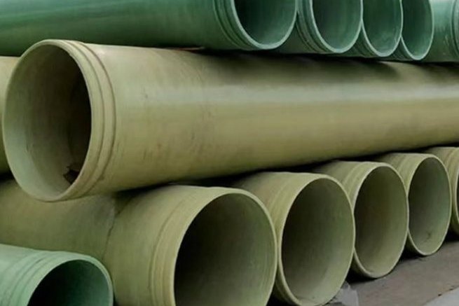
Produced water is the largest single fluid stream in an oilfield and the one most often mis-specified, because it is usually described by an operator as "just brine" in the inquiry and then arrives at the pipe with 200,000 mg/L of chloride, dissolved hydrogen sulphide, dispersed oil, barium and strontium, and a temperature that has cooled from 80 °C at the wellhead to something else entirely at the disposal manifold. Carbon steel lines in this service fail from the inside out at a rate that makes the material substitution obvious, and FRP lines fail for a completely different reason — a joint that was fine at 65 bar on the test bench, assembled in a 4 °C night shift without cure control, or a pressure rating that was quoted on a static basis and then used cyclically. This guide works through the four decisions that actually determine whether an FRP line survives: what is in the water, which pressure class applies, which resin and liner see the chemistry, and which joint family is being asked to hold the load.
1. What Is Actually in the Water: The Design Envelope
Start with the fluid, because every downstream decision follows from it. Produced water composition varies from formation to formation and changes over the life of a single well — water cut commonly climbs from a few per cent to 95 % or more, which is why disposal capacity is almost always a late-life problem rather than an early-life one.
| Parameter | Typical range in produced water | Why it matters to the pipe |
|---|---|---|
| Total dissolved solids (TDS) | 5,000–300,000 mg/L; offshore 10,000–35,000; shale and tight oil 20,000–300,000 | Drives resin and liner selection; rules out standard polyester in the upper range |
| Chloride | Dominant anion, tracks TDS | Chloride stress corrosion is a metals problem, but chloride ingress still governs liner thickness |
| Dissolved H₂S | Variable, from absent to several hundred mg/L | Sour service; the reason a plain isophthalic system is not acceptable |
| CO₂ | Present, often in equilibrium with carbonates | Lowers pH, increases aggressiveness to the corrosion barrier |
| Oil in water | 100–2,000 mg/L onshore; 100–1,000 mg/L dispersed offshore | Solvent attack on the liner; also a wetting problem at joints |
| Scale-forming ions | Ba²⁺, Sr²⁺, Ca²⁺, Mg²⁺ | Barium and strontium sulphate scale is hard and abrasive; deposits raise local velocity |
| Temperature | 40–90 °C at the wellhead; lower after separation and tankage | Sets the temperature partial factor in the design envelope |
| Suspended solids | Sand, formation fines, iron sulphide | Erosion at bends and tees; solids settling in low-velocity runs |
Two consequences are worth stating plainly. First, "brine" is not a specification. A line designed for 20,000 mg/L at 35 °C is not the same product as one designed for 200,000 mg/L at 80 °C with dissolved H₂S, even at identical diameter and pressure. Second, the water chemistry you are handed at inquiry stage is almost always from an early well test. Write the design basis around a chemistry envelope with a stated margin, and put the sampling and analysis requirement in the purchase order so there is a documented basis when the produced water changes.
2. The Pressure Class Decision: API 15LR vs API 15HR
Oilfield fibreglass line pipe is bought against two API specifications and they are not interchangeable. The split is a pressure-class split, not a resin split, and the design basis underneath them is different in a way that matters when you convert from static to cyclic duty.
| API Spec 15LR | API Spec 15HR | |
|---|---|---|
| Full title | Specification for Low Pressure Fiberglass Line Pipe and Fittings | Specification for High Pressure Fiberglass Line Pipe |
| Current edition | 7th Edition, August 2001 (Errata 2018 and 2021) | 4th Edition, February 2016 (Errata 1: 2016, Errata 2: 2021) |
| Pressure scope | Cyclic operating pressures up to and including 1,000 psig (≈ 69 bar) | 500 psig to 5,000 psig (≈ 34.5 bar to 345 bar) |
| Size scope | Diameters up to and including 16 in. (≈ DN400) | High-pressure line pipe and fittings; threaded connections are addressed here |
| Design basis test | ASTM D2992 Procedure A — elevated-temperature (150 °F) multi-specimen cyclic pressure test | ASTM D2992 Procedure B — elevated-temperature (150 °F or higher) multi-specimen static pressure test |
| Resins permitted | Thermosetting resin systems | Epoxy, polyester, vinyl ester and phenolic, glass-reinforced; thermoplastic resins excluded |
| Typical oilfield duty | Lower-pressure gathering, produced-water and utility lines | High-pressure injection, reinjection and corrosive high-pressure flowlines |
The trap is that a 15HR rating is derived from a static regression, while a 15LR rating is derived from a cyclic one. If you take a 15HR number and apply it to a service that cycles every day, you have used the wrong basis. Operators surveyed in the US Bureau of Safety and Environmental Enforcement research report 230-AJ reported a range of conservative practices against the API ratings, and one of them applied a conversion factor of about 0.51 to move a 15HR static rating to a cyclic rating — the product of taking 0.6 of the HR value and then applying a further 0.85 installation and loading margin. Others derated to between 64 % and 88 % of the manufacturer's rating. Whatever margin you choose, choose it deliberately and write it down.
In practice the pressure class also drives the joint. Salt water disposal wells commonly inject at 500 to 2,000 psi and sometimes higher, which sits squarely in the 15HR band for small and medium diameters; produced-water gathering upstream of the disposal pump usually sits in the 15LR band. Do not merge this with spoolable reinforced thermoplastic pipe — that is a different product form with a different specification, and its flexibility numbers are not transferable.
3. Resin and Liner Selection for H₂S, CO₂ and High Chloride
The structural laminate carries the pressure. The liner — the resin-rich inner layer in contact with the fluid — decides whether the pipe is still there in twenty years. They are selected independently.
For the structural winding, the resin choice is a temperature and cost decision. Epoxy (giving the "GRE" designation that dominates oilfield high-pressure service) provides the best combination of strength, temperature capability and toughness. Vinyl ester gives excellent chemical resistance at a lower cost and is the workhorse for aggressive produced water at moderate pressure. Isophthalic polyester is the economic option for benign, lower-temperature, lower-TDS service; orthophthalic polyester should not be offered for sour or high-chloride duty at all.
For sour service specifically, the two things that matter are the resin's resistance to sulphide-induced degradation and its resistance to hydrolysis at temperature. Bisphenol-A epoxy and novolac epoxy systems are the standard choices where dissolved H₂S is present at temperature; standard vinyl ester is acceptable for milder sour duty but should be checked against the actual H₂S partial pressure and temperature rather than approved on the basis of "vinyl ester resists acids".
The qualification framework for non-metallic materials in oilfield service is the ISO 23936 series. Part 1 covers thermoplastics, Part 2 covers elastomers, Part 3 covers thermosets but explicitly excludes continuous fibre-reinforced composites and excludes tubular products and tanks made from them, and Part 4 (first edition, 2024) covers fibre-reinforced composite materials and does include non-metallic pipelines and liners. If your technical file cites ISO 23936-3 for an FRP line pipe, it is citing the wrong part. NORSOK M-710 remains the reference for non-metallic sealing materials and is widely adopted outside Norway.
4. Corrosion Barrier Construction
Filament-wound pipe to ASTM D2996 is manufactured by winding continuous glass strands impregnated with thermosetting resin onto a mandrel at a controlled angle, conventionally 54½° for internal-pressure service because hoop stress is twice axial stress in a closed cylinder and that angle gives the laminate a 2:1 strength bias. The specification covers machine-made reinforced thermosetting resin pipe up to 60 in. nominal size and applies where the outside diameter to wall thickness ratio is 10:1 or more.
The liner is built first and is deliberately resin-rich. Typical construction for a chemical-service pipe is a synthetic surface veil, then a glass veil, then chopped-strand mat layers to reach the specified liner thickness, with minimum resin contents around 80 % in the veil layers and 60 % in the mat layers. Published ASTM D2996-type product data puts nominal liner thickness in the region of 2.5 mm (100 mil) for corrosion service; ISO 14692 and ASME RTP-1 use similar values, with RTP-1 historically requiring a 100 mil (2.54 mm) inner liner for its higher classes.
The barrier's job is to keep the aggressive medium away from the structural glass. That means the specification that matters is not wall thickness but liner thickness, resin content and void content, plus the qualification evidence that the chosen resin survived the actual chemistry at the actual temperature. Ask for the chemical resistance data at service temperature, not at 23 °C.
5. Joint Selection: Five Families and Where Each One Fits
GRP systems stand or fall on their joints, and this is where the largest single cost and schedule difference between a good and a bad project sits. There are five families in common use.
| Joint family | How it works | Axially restrained? | Practical envelope | Where it fits |
|---|---|---|---|---|
| Adhesive-bonded tapered bell & spigot | Machined tapered spigot into a conical bell, structural adhesive, finishing fillet | Yes | Recommended up to about DN600 and up to 65 bar | Small and medium bore high-pressure lines; lowest material cost. Make-up gets difficult above DN600 |
| Butt and wrap (laminated) | Plain ends aligned and hand-laminated with resin and glass; outer surface abraded or tapered, taper not steeper than 1 in 6 | Yes | All diameters; becomes field-intensive at large sizes | Buried lines and permanent installations; rebuilds the full structural wall when done properly |
| Mechanical O-ring bell & spigot with locking strip | Factory-integral socket, elastomeric seals, optional locking key for tensile restraint | Only with the locking strip | Pressure class of the coupling | Fast assembly, tolerates small axial and angular movement; good for poor site conditions |
| Flanged | Flat-faced FRP flange, gasket, bolted to arbitrary equipment | Yes | Bolt pattern per ASME B16.5 / B16.47 | Tie-ins to pumps, valves, vessels and steel piping. Always pair flat-face to flat-face |
| Threaded | API or proprietary threads on pipe ends | Yes | Recommended above about 70 bar | High-pressure oilfield strings; end connections to API 15HR |
Field assembly discipline is what separates these in service, not the geometry. The failure modes are depressingly consistent on laminated joints: insufficient surface preparation so the overlay bonds to weathered resin rather than fresh glass; lamination carried out in damp or cold conditions without a heated enclosure; under-thickness build-up; and dry glass from poor wet-out. The procedural answer is to treat jointers as a qualified trade — qualify them, log ambient temperature and humidity per joint, and run a Barcol hardness check on every cured laminate before backfill or insulation hides it.
6. The Derating Chain: From Burst Test to a Pressure You Can Sign
FRP has no single allowable stress. Long-term capability is established by regression testing — pressurising samples for thousands of hours and extrapolating the failure envelope to 50 years on a log-log plot per ASTM D2992 or ISO 14692 — and then scaled down by a chain of factors. Knowing the chain lets you check a supplier's number instead of accepting it.
The operator rules reported in the BSEE survey are a useful cross-check against a short-term burst test to ASTM D1599:
- Static long-term pressure rating = (1 / 5) × short-term burst × 0.85
- Cyclic service rating = (1 / 7.5) × short-term burst × 0.85
| Short-term burst (ASTM D1599) | Burst (psi) | Static long-term rating | psi | Cyclic rating | psi |
|---|---|---|---|---|---|
| 16.0 MPa | 2,321 | 2.72 MPa | 395 | 1.81 MPa | 263 |
| 20.0 MPa | 2,901 | 3.40 MPa | 493 | 2.27 MPa | 329 |
| 24.0 MPa | 3,481 | 4.08 MPa | 592 | 2.72 MPa | 395 |
| 32.0 MPa | 4,641 | 5.44 MPa | 789 | 3.63 MPa | 526 |
| 40.0 MPa | 5,802 | 6.80 MPa | 986 | 4.53 MPa | 658 |
On top of the regression basis, ISO 14692-3:2017 applies a part factor for loading, f₂, whose recommended values are 0.67 for sustained loading, 0.83 for sustained loading combined with self-limiting displacement, and 0.89 for occasional loading. For the field hydrotest case the standard sets the partial factors A₀, A₂ and A₃ to 1.0 with f₂ = 0.89. The full design expression is:
Pqualified ≥ Pdesign / (f₂ × A₁ × A₂ × A₃)
where A₁ is the temperature partial factor, A₂ the chemical resistance factor and A₃ the cyclic service factor. All three come from the standard's tables and from the material qualification data, and all three are less than or equal to 1.0. This is why the required qualified stress climbs faster than intuition suggests:
| Design pressure | Required qualified, f₂ = 0.67 | Required qualified, f₂ = 0.83 | Required qualified, f₂ = 0.89 |
|---|---|---|---|
| 1.0 MPa | 1.49 MPa | 1.20 MPa | 1.12 MPa |
| 1.6 MPa | 2.39 MPa | 1.93 MPa | 1.80 MPa |
| 2.5 MPa | 3.73 MPa | 3.01 MPa | 2.81 MPa |
| 4.0 MPa | 5.97 MPa | 4.82 MPa | 4.49 MPa |
| 6.9 MPa | 10.30 MPa | 8.31 MPa | 7.75 MPa |
Read the f₂ = 0.67 column as the honest one for a disposal line. A line that runs at a steady pressure all day and cycles at every pump start is a sustained-load case, not an occasional-load case, and the difference between 0.67 and 0.89 is a third of the allowable pressure.
7. Surge and Water Hammer in Disposal Lines
GRP systems are more sensitive to surge and water hammer than steel systems of the same rating, for a straightforward reason: the lower elastic modulus means the pressure wave travels more slowly and the pipe walls are thinner, so a given velocity change produces a larger pressure rise relative to the allowable. The Joukowsky relation gives the first-order estimate:
Δp = ρ · c · Δv
with ρ the fluid density, c the pressure wave speed and Δv the change in flow velocity caused by a valve closure, pump trip or check-valve slam. Wave speed in jointed GRP generally falls in the 300–700 m/s band; a fully restrained, rigidly jointed line sits at the top of that range, and elastomeric-seal joints pull it down because the joints themselves are compliant.
| Velocity change Δv | c = 300 m/s | c = 400 m/s | c = 600 m/s | c = 700 m/s |
|---|---|---|---|---|
| 0.5 m/s | 0.150 MPa | 0.200 MPa | 0.300 MPa | 0.350 MPa |
| 1.0 m/s | 0.300 MPa | 0.400 MPa | 0.600 MPa | 0.700 MPa |
| 1.5 m/s | 0.450 MPa | 0.600 MPa | 0.900 MPa | 1.050 MPa |
| 2.0 m/s | 0.600 MPa | 0.800 MPa | 1.200 MPa | 1.400 MPa |
| 3.0 m/s | 0.900 MPa | 1.200 MPa | 1.800 MPa | 2.100 MPa |
All values in MPa; multiply by 145.04 for psi.
On a 1.6 MPa line, a 3 m/s velocity change at the stiff end of the wave-speed range adds 2.1 MPa of surge — more than the line's own rating. The engineering responses are conventional: keep steady-state velocity moderate by sizing up a step, specify a closure time long enough that the wave has time to reflect and relieve, use pump discharge and check valves with damped or slow-closing characteristics, and do not put a fast-acting isolation valve at the end of a long dead-end run.
8. Thermal Movement, Anchor Forces and Support Spacing
Produced water arrives hot and cools along the route, which is exactly the situation that generates axial movement in a restrained line. Two numbers explain why GRP behaves so differently from steel in this service.
In a fully restrained pipe the axial stress generated by a temperature change is σ = Ea · α · ΔT, and the anchor force is that stress times the wall area. Because the axial modulus of GRE is roughly 12,600 MPa against 203,000 MPa for carbon steel, and its expansion coefficient is about 18 × 10⁻⁶ /°C against 11.7 × 10⁻⁶ /°C for steel, the restrained stress in GRP is around a tenth of the steel value:
| Size | OD (mm) | Wall (mm) | σ axial, GRE @ ΔT = 45 °C | Force, GRE | σ axial, carbon steel | Force, carbon steel |
|---|---|---|---|---|---|---|
| DN80 | 89 | 3.0 | 10.2 MPa | 8.3 kN | 106.9 MPa | 86.6 kN |
| DN150 | 159 | 4.5 | 10.2 MPa | 22.3 kN | 106.9 MPa | 233.4 kN |
| DN200 | 219 | 6.0 | 10.2 MPa | 41.0 kN | 106.9 MPa | 429.1 kN |
| DN300 | 315 | 8.0 | 10.2 MPa | 78.7 kN | 106.9 MPa | 824.7 kN |
The free expansion is still substantial: a 200 m run with a 45 °C swing moves 200 × 18 × 10⁻⁶ × 45 = 0.162 m, or 162 mm. That is not going to be absorbed by joint tolerance, so the route needs expansion loops, guided offsets or an anchor scheme — and because the anchor forces are an order of magnitude lower than steel, a GRP line can often be anchored to structures that a steel line could not use.
Support spacing is governed by deflection, with a bending stress check as the second gate. The usual deflection limit is the smaller of 12.5 mm and 0.5 % of the span. Working the beam equation for a GRE line carrying water, with an allowable long-term bending stress taken conservatively at 6 MPa — well below the roughly 100 MPa short-term beam-bending ultimate — gives:
| Size | Moment of inertia (mm⁴) | Distributed load (N/mm) | Span by deflection (m) | Span by bending stress (m) | Governing span |
|---|---|---|---|---|---|
| DN80 | 7.50 × 10⁵ | 0.068 | 3.40 | 3.45 | Deflection — 3.4 m |
| DN150 | 6.52 × 10⁶ | 0.214 | 4.38 | 4.29 | Stress — 4.3 m |
| DN200 | 2.28 × 10⁷ | 0.405 | 5.11 | 4.97 | Stress — 5.0 m |
| DN300 | 9.10 × 10⁷ | 0.832 | 6.03 | 5.77 | Stress — 5.8 m |
Support hardware has its own rules that are routinely ignored. Every support should present a contact width of at least 100 mm or one third of the pipe diameter, whichever is greater, and wear saddles or elastomeric pads should be used so the pipe is not abraded by the support itself. Guides need 2–3 mm of clearance to prevent binding and localised stress concentration as the line expands and contracts. Above-ground runs in hot climates should be checked for solar heating on top of the process temperature — a black-painted GRE line in direct sun can run well above the fluid temperature.
9. Flow, Solids and the Operating Envelope Below the Rating
The hydraulic advantage of FRP in produced water service is real and easy to quantify. A Hazen-Williams C of 150 and an absolute roughness of 0.0053 mm (0.00021 in) are the standard published figures for filament-wound FRP pipe. Against new cement-lined steel at C = 120, that is roughly a 1.5 : 1 head-loss advantage at the same diameter — which is often the difference between needing a booster station and not.
| Nominal size | Inside diameter | Flow | Velocity | Head loss, FRP (C = 150) | Head loss, cement-lined steel (C = 120) |
|---|---|---|---|---|---|
| DN150 | 150 mm | 100 m³/h | 1.57 m/s | 13.43 m/km | 20.31 m/km |
| DN200 | 207 mm | 100 m³/h | 0.83 m/s | 2.80 m/km | 4.23 m/km |
| DN200 | 207 mm | 200 m³/h | 1.65 m/s | 10.10 m/km | 15.27 m/km |
| DN300 | 299 mm | 400 m³/h | 1.58 m/s | 6.09 m/km | 9.20 m/km |
The velocity window on a produced-water line has to satisfy three conflicting requirements, and the target range is project-specific rather than fixed by a single standard:
- Low end — the velocity must be high enough to keep sand, formation fines and iron sulphide moving. Below the deposition threshold, solids settle in horizontal runs and at the bottom of bends; the deposit then raises the local velocity over the top of it, which is how erosion starts.
- Middle — barium, strontium and calcium sulphate scales deposit on the liner when the water chemistry shifts. Higher velocity reduces scaling, so the design velocity is normally set above the deposition threshold with margin.
- High end — FRP tolerates erosion far better than steel in chloride service but not indefinitely, and erosion rate rises steeply with velocity and with solids loading. Bends, tees and reductions are worth specifying with a thicker liner or one size up.
Because the pipe is non-conductive and often buried, this is also the point at which to settle the electrical question. In classified areas, static dissipation becomes a design requirement rather than a preference: ESD-dissipative materials in the range of 10⁶ to 10⁹ Ω per square are the usual target for equipment in potentially explosive atmospheres. Antistatic FRP pipe constructions exist for this purpose and should be specified at the inquiry stage, because retro-fitting continuity to a non-conductive line after installation is not practical.
10. Field Hydrotest, Joint QA and the Documentation That Protects You
Acceptance on an FRP produced-water line is a documentation exercise as much as a pressure test. The test methods are individually well defined, and the temptation to substitute one for another is the usual source of argument.
| Check | Method | What it establishes |
|---|---|---|
| Short-term hydraulic burst | ASTM D1599 | Upper anchor for the pressure rating chain; basis of the 1/5 and 1/7.5 field rules |
| Time to failure under constant pressure | ASTM D1598 | Regression data for the long-term envelope |
| Hydrostatic or pressure design basis | ASTM D2992, Procedure A or B | HDB regression; Procedure A for cyclic, B for static |
| Cyclic pressure strength | ASTM D2143 | Fatigue capability for pump-cycling service |
| Longitudinal tensile properties | ASTM D2105 | Axial capability — what the anchors and restrained joints see |
| External load characteristics | ASTM D2412 (parallel plate) | Buried ring stiffness and deflection behaviour |
| Dimensions | ASTM D3567 | Diameter, wall and liner thickness confirmation |
| Classification | ASTM D2310 (withdrawn 2017, still widely cited in project specs) | Four-character cell classification by type, grade and liner |
The field hydrotest itself follows the ISO 14692 envelope: f₂ = 0.89 with the partial factors set to 1.0, which is why the hydrotest pressure comes out above the sustained-load rating but must never be taken above 1.5 times the rated pressure of the class. A worked example: a pipe with a 32 MPa short-term burst gives a 5.44 MPa static long-term rating by the 1/5 × 0.85 rule, and a hydrotest on the occasional-load basis of 5.44 / 0.89 = 6.11 MPa, or about 887 psi. Test the line, record it, and do not leave a line under test pressure longer than the procedure requires.
Three items belong in the handover pack for every jointed GRP produced-water line, and their absence is what makes warranty arguments unwinnable:
- Ambient temperature and relative humidity logged for every laminated or adhesive joint, with the adhesive batch number and the cure time achieved.
- Barcol hardness readings on every cured laminate, taken before backfill, against the resin supplier's specified minimum.
- A hydrotest record per test section with the pressure, hold time, ambient temperature and the certified gauge used.
Specifying an FRP Produced-Water and Disposal Line
Write the design basis before you write the pipe size. State the chemistry envelope with chloride, TDS, dissolved H₂S and oil content at maximum and normal conditions; the temperature envelope including pump and solar cases; the pressure basis and whether it is static or cyclic, with the API specification edition and errata named; the required qualified stress from the ISO 14692 chain; the joint family per diameter; and the test evidence you will witness. Everything else — resin, winding angle, liner thickness, support spacing — follows from those six lines.
Related reading on this site: installation, jointing and field pressure testing of FRP pipe, support spacing and hanger design, long-term hydrostatic strength, ASTM D2992 and the 50-year HDB basis, FRP pipe for desalination and brine service, resin selection for chemical equipment, thermoplastic liners for aggressive chemical service, matching flanges and fittings to pipeline ratings, buried GRP bedding, backfill and ring deflection, antistatic FRP pipe and static dissipation and trenchless installation by jacking and sliplining. The pipe itself is available in the filament-wound FRP process pipe range and as high-pressure FRP pipe and FRP water pipe, with connections from the FRP flange and fitting range, all under pipes and fittings.
Need help selecting FRP products?
Our engineers answer technical questions free of charge.
Ask an Engineer on WhatsApp