
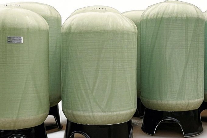
A water test is the most misleading word in tank commissioning. On a steel tank, "hydrotest" means pressurising to 1.5 times design pressure and watching the gauge. On an atmospheric FRP tank there is no 1.5×: the test is a structural event — you are deliberately filling the vessel with tens of tonnes of water to prove the laminate, every joint, every secondary bond and, just as importantly, the foundation underneath it. Done casually, a first fill can be the most aggressive load cycle the tank ever sees. Done properly, it is the single most informative day of the tank's life: it validates the shell, the nozzle penetrations, the base-to-shell joint and the earthworks in one controlled exercise.
This guide covers the sequence we hand to site teams for filament-wound GRP tanks built to ASTM D3299 or ASME RTP-1, and for contact-moulded tanks to ASTM D4097: what each standard actually requires from the water test, how fast to fill and why, what to watch for in the foundation, and how to hand the tank over to product without undoing everything the test proved. Throughout, the worked example is a vertical tank with a 3.0 m inside diameter, 4.0 m shell height and a 10 mm structural wall — the arithmetic scales, the logic does not.
1. What the Water Actually Does to the Shell
Before any procedure, it is worth being clear about the load. At the design liquid level, the gauge pressure at the bottom of our example tank is:
p = ρ·g·H = 1,000 kg/m³ × 9.81 m/s² × 4.0 m = 39.2 kPa
That pressure produces a hoop stress in the wall of σ = p·D/(2t) = 39.24 × 3,000/(2 × 10) ≈ 5.9 MPa, or a hoop strain of roughly 0.024 % against a 25 GPa laminate modulus — an order of magnitude below the 0.2–0.3 % strain design limits used in EN 13121-3 or BS 4994 calculations. That is the point: the water test is not a proof-pressure exercise in the way it is for a pressure vessel. It loads the shell to a small fraction of its design capability, which is exactly why leakage, not deformation, is what the test is looking for. Weeps, damp patches and wicking at secondary bonds show up at 39 kPa long before the strain gauges would care.
Two consequences follow. First, exceeding the design liquid level "to be safe" buys you nothing structurally and distorts the test: the shell above HWL is often not reinforced for liquid head, and the roof-to-shell joint is not designed to retain liquid at all. Second, because the loads are low, a passed test tells you the workmanship is sound — it does not by itself tell you the foundation is adequate. That is what the settlement survey in Section 6 is for.
2. Shop Test, Field Test and What Each Standard Requires
FRP tank standards draw a clean line between the manufacturer's shop test and the site acceptance test, and they do not demand the same thing from both.
| Standard | Test required | Key parameters | What it proves |
|---|---|---|---|
| API 12P (shop or field) | Hydrostatic test | Clean fresh water with surfactant added; fill through a temporary standpipe to 12 in. (0.30 m) above the top crown; hold ≥ 4 hours; all nozzles blinded with the fittings intended for service; any repair → retest ≥ 2 hours | Laminate and all joints sealed under a small positive head above the highest stored level |
| ASTM D3299 / D4097 (manufacturing specs) | Hydrostatic test per the purchase data sheet, shop or field | Test conducted on the completed tank; thickness, Barcol cure and acetone surface-cure checks alongside | The delivered tank matches its design basis |
| ASME RTP-1 (vessels) | Fill test / proof pressure per RTP-1 rules | Atmospheric tanks are tested filled; pressurised proof only within the MAWP the certification actually covers | Design and fabrication per the RTP-1 quality system, with the Certified Design Report and MDR |
| EN 13121-3 (GRP tanks/vessels) | Inspection and testing before handover; Annex C covers the pressure and leak testing | Applies above-ground, non-pressurised to 10 bar, −40 °C to +120 °C | European design/workmanship conformity for the delivered tank |
The standpipe detail in API 12P deserves emphasis. Filling 12 inches above the top crown puts a small positive head on the roof-to-shell junction — the one joint that never sees liquid in service. It is a cheap, deliberate overshoot, not an accident, and it is why the procedure specifies a temporary standpipe rather than "fill it up". If your tank has an open vent, the standpipe head is limited by the vent lip elevation; blind the vent only if the test plan says so and the shell has been checked for the pressure it can take.
API 12P also insists that all connections be plugged or blinded during the test with the type and size of fittings intended for use after installation — because a joint sealed with a shop blank proves nothing about the flanged joint that will actually carry product.
3. Preparing the Tank and the Water
Preparation is where most failed tests are actually created. Work the list before the first litre goes in:
- Water quality: clean fresh water, per API 12P with a surfactant added so that fine weeps wick visibly instead of being masked by surface tension. Do not test with seawater or brackish water; chlorides and the tank's gelcoat barrier deserve the respect described in our article on hydrotest water quality, chloride limits and post-test drying.
- Temperature: fill water within a moderate range of the tank's own temperature. A cold water fill into a tank that has been sun-heated all morning puts the gelcoat into tension; stage the fill and let temperatures equalise.
- Blinding: every process, instrument and vent connection either blinded with its service fitting or open as the test plan allows. Count the blanks against the nozzle schedule before starting.
- Groundwork: the foundation must be complete, cured and surveyed (Section 6). Anchor bolt torque recorded. Access for inspection around the full circumference — you will be walking it.
- Supports and attachments: ladders, platforms and pipework either installed with their final loads present, or deliberately deferred and noted. A hydrotest with none of the service piping attached quietly skips the settlement the real loads will cause.
- Standpipe: sized to reach 0.30 m above the top crown, with a controlled fill connection and a level you can actually read.
On multi-section tanks assembled on site, the secondary-bond joints are the items under the microscope. If the erection crew worked in less-than-ideal conditions, say so in the test plan and extend the observation window — a 4-hour hold catches a bad joint; a marginal one often announces itself overnight.
4. Fill Rate: Why You Fill Slowly and in Stages
The obvious question is "how fast can we fill?" — and the honest answer is that the shell does not care much (0.024 % strain is nothing), but the foundation does. Water loading is applied far faster than any soil consolidation, so the rate of fill is really a rate of load application to the ground. Filling in stages with holds gives the foundation time to reveal what it intends to do, and gives the survey crew clean reading points.
Our worked example at 30 m³/h:
| Stage | Liquid level | Cumulative volume | Time at 30 m³/h | Record before continuing |
|---|---|---|---|---|
| 25 % | 1.00 m | 7.1 m³ | 14 min | Perimeter survey pass 1; check base-to-shell joint, all blinding flanges |
| 50 % | 2.00 m | 14.1 m³ | 28 min | Survey pass 2; visual of lower shell from outside; manway gaskets |
| 75 % | 3.00 m | 21.2 m³ | 42 min | Survey pass 3; check any bonded attachments under increasing load |
| 100 % | 4.00 m | 28.3 m³ | 57 min | Survey pass 4, then the formal hold (≥ 4 h, API 12P) |
| Hold | 4.30 m | 30.4 m³ | +4 min | Standpipe head on the roof joint; hold and inspect inside and out |
Two habits make staged filling worth the bother. First, take the survey passes at constant, recorded times after each stage, so that settlement readings are comparable. Second, hold each stage long enough for a person to walk the outside of the tank — damp patches on the foundation or the lower shell are 90 % of early findings.
5. Venting During Filling: The Check Everyone Forgets
Every litre of water entering the tank displaces a litre of air — the vent has to pass it in reverse, or you pressurise an atmospheric tank. The displacement demand equals the fill rate, roughly 1:1 by volume, and API 2000's thermal inbreathing rules add a smaller second term for vapour contraction on cold nights (its normal-entry figures work out near 1:1 with pumping volume too).
Check the vent the way you would check a pump: area and velocity.
| Vent | Free area | Air velocity | Passes | Verdict for a 30 m³/h fill |
|---|---|---|---|---|
| DN100 | 0.0079 m² | 1.06 m/s | 30 m³/h | Adequate, but little margin for thermal terms and fouling |
| DN150 | 0.0177 m² | 0.47 m/s | 30 m³/h | Comfortable; typical choice for this tank size |
| DN150 fouled 50 % | 0.0088 m² | 0.94 m/s | 30 m³/h | Still passes — but this is why vents get inspected, not assumed |
The classic failure is not an undersized vent on paper; it is a vent plugged by a wasp nest, blanked off for painting and never re-opened, or a flame arrester that has never been cleaned. During the test, someone should physically verify air movement at the vent as the level rises — a hand at the vent mouth or a light tissue will do. For the design side of vacuum and external pressure on FRP shells, see our tank vacuum and external pressure design guide; the shell that survives a blocked vent during filling is rarely the shell that survives it during pumping-out.
6. Watching the Foundation: Settlement Surveys and What to Record
The settlement survey is the part of a hydrotest that outlives the test. API 653's Annex B — written for steel tanks but widely used as the screening framework for any large flat-bottomed vessel — shows what a defensible survey looks like:
- Points: evenly spaced around the shell, an even number, at least eight (API 653's N = D/10 rule with D in feet), never farther apart than about 9.58 m. On our 3 m tank, eight points give a 1.18 m spacing — generous by steel-tank standards, and FRP benefits from more points, not fewer.
- Baseline: record elevations before the fill starts, and again after each stage and after the hold.
- Tilt: rigid-body tilt across the diameter is screened against 1:120 in the steel framework — 25 mm across our 3 m diameter. FRP shells and their bonded attachments are less forgiving of twist than a welded steel shell, so treat 1:120 as a reference figure to confirm with the tank designer, not a licence.
- Out-of-plane distortion: API 653 fits a cosine curve to the readings (valid at R² ≥ 0.90) and compares residual deviations against allowable values that scale with arc length; edge settlement and local bottom depressions have their own curves and a 0.37·R (in/ft) reference for local bulges. If the survey needs that machinery, the FRP tank's designer should be in the room — laminate creep makes the steel criteria optimistic, not conservative.
For FRP specifically, add two items the steel framework does not know about. Creep: GRP continues to strain under sustained load for weeks, so re-survey at 24 h and again at one month after first fill; a tank that is still moving may be settling — or creeping — and only the trend tells you which. And attachments: settlement that a steel shell shrugs off can overload a rigid bonded or bolted pipe connection, which is why service pipework should have its flexibility checked after the survey, not before the fill.
7. Acceptance Criteria and the Punch List
Acceptance is a set of observable, binary criteria — write them into the test plan before filling, not after:
| Observation | Method | Accept | Reject / action |
|---|---|---|---|
| Leakage at base-to-shell joint | Visual, inside and out, during hold | Dry joint, no damp ring on foundation | Damp ring or weep: mark, drain to below joint, repair per manufacturer, retest ≥ 2 h (API 12P) |
| Weeping on shell or secondary bonds | Visual with surfactant in the water; torch at night | No wicking, no damp patches | Any wicking = find and repair; retest |
| Gelcoat condition | Visual | No cracking, crazing or whitening | Crazing signals over-load or thermal shock — stop, review, do not proceed |
| Nozzle and flange joints | Visual at each blinded connection | Dry gasket faces | Weep at flange: re-torque per our flange bolting practice; if the laminate weeps, it is a repair |
| Vent | Physical check during fill | Air movement confirmed | No movement: stop filling immediately and clear |
| Foundation | Survey passes | Within screening limits; no new cracking in ring beam or plinths | Excess or accelerating movement: hold, investigate before continuing |
| Anchor bolts | Visual + torque check after hold | No movement, torque retained | Any loosening: re-torque and log; repeated loosening needs the designer |
Note what is not on the list: "no visible change" of the shell. Some bulging at the lower courses during a first fill is normal elastic response; it should disappear when the tank drains. What matters is that it does disappear — which is another reason to look at the tank both full and empty.
8. Draining and Drying Without Creating a Vacuum
The tank that passed the test can still be damaged on the way out. Draining faster than air can enter through the vent collapses atmospheric tanks — every year, reliably. Size the drain against the vent: our DN150 vent passes about 64 m³/h at 1 m/s, so the drain valve on this tank should be throttled well below that until you have watched the vent working at full drain flow. If the tank has a vacuum relief valve, confirm its setting against the pump-out scenario described in our vacuum design guide before trusting it.
After draining:
- Dry the interior — standing water in the knuckle and under manways leaves tide marks and, in chlorinated service, chloride residues. Ventilate; do not heat-blast a closed tank.
- Inspect what the test uncovered: tide marks mark exactly where weeps were; photograph them.
- Re-survey the empty tank; compare against the full-tank readings to separate elastic recovery from real settlement.
- Plan the product fill: the first product fill repeats the staged sequence, usually at a slower rate than water (product is often denser, and the operator is watching instruments rather than a test crew). If the medium is temperature-sensitive, remember the tank's insulation and heat-tracing design was validated for water, not for your product.
9. Handing Over: From Water to Product
First product fill is where test thinking meets operating discipline. Before the valve opens, the operating limits from our next article — level alarms, overfill setpoints and the vent envelope — should already be configured, because a fill with no working level indication is a test of the vent, not of the crew. Confirm:
- Level instrumentation powered and cross-checked against a manual dip or the standpipe reading.
- High-level alarm demonstrated (not just displaying — demonstrated).
- Vent and emergency venting clear; flame arresters cleaned if fitted.
- Bund or containment dewatered (test water must not sit in the bund when product arrives).
- Foundation survey trend reviewed: if the tank was still settling at handover, the product fill plan should say so and prescribe hold points.
Where the product differs meaningfully from water — density, temperature, vapour pressure — the designer should confirm the shell for the real liquid, not for water. Water at SG 1.0 is a conservative test medium for most chemicals, but hot service, dense brines and phase-separating products each remove a little of that margin.
10. The Records That Make the Test Worth Doing
A hydrotest nobody can document is a hydrotest that never happened, as far as any future inspection is concerned. The handover pack should contain: the test plan with acceptance criteria; water source and quality note; blind list matched to the nozzle schedule; fill and hold times with standpipe head; the survey baseline and every stage reading; photographs of joints, gaskets and the vent; punch list with repairs and retest durations; anchor bolt torques before and after; and the signed acceptance. Twenty years from now, the question will not be "did it leak?" but "what did the foundation do between the baseline and stage three?" — and only the records answer that.
A hydrotest proves the tank. The settlement survey proves the ground. The paperwork proves both — and on the day something changes years later, the paperwork is the only witness that was there.
Ready to put a tank on site? Our filament-wound GRP industrial storage tanks and vertical corrosion-resistant FRP tanks ship with a hydrotest and handover procedure matched to the standard you specify — tell us the medium, the standard and the foundation type, and we will return the fill schedule and survey plan with the offer. For the standards behind the test, see our guides to hydrotest water quality, tank transport and installation and vacuum and external pressure design; for the joints under test, see field erection and joint lamination and nozzle and manway design.
Need help selecting FRP products?
Our engineers answer technical questions free of charge.
Ask an Engineer on WhatsApp