
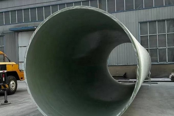
Hydrostatic testing is the last chance to find a defect before a line or a vessel goes into service, and the water used for it is usually chosen by whoever has a hose. For carbon steel that is often acceptable. For FRP and GRP it is not, because the test fluid spends hours in contact with a laminate that absorbs water, and with the stainless steel nozzles, instrument tappings and gaskets that are bolted into it. The damage that a poor water choice causes does not appear during the test; it appears two or three years later as blistering, weeping joints or a cracked nozzle weld.
This guide separates the two problems that get confused under the heading of water quality: what the water does to the metal components, and what it does to the laminate. It then works through the parameters that matter - chloride, temperature, pH, solids, free chlorine - with the limits from the governing standards, the arithmetic behind each limit, and the post-test drying step that most procedures omit. Pressure and hold-time acceptance is covered in FRP pipe installation and pressure testing; this article is about the fluid itself.
1. Two Failure Modes, One Water Sample
An FRP system is not a single material. It is a laminate, a liner, an adhesive or laminated joint, and a set of metallic and elastomeric components. The same test water can be harmless to one and damaging to another, and the governing limit is always the most sensitive item in the test boundary.
| Water parameter | Component at risk | Mechanism | When the damage shows |
|---|---|---|---|
| Chloride | Stainless nozzles, instrument taps, dissimilar metal joints | Pitting and chloride stress corrosion cracking under residual stress | Weeks to years; often as a leak at a weld or a thread |
| Dissolved salts | Laminate and liner | Osmotic absorption, blister formation under a semi-permeable skin | First hot excursion after commissioning |
| Temperature | Resin, joints, gaskets | Modulus and strength reduction, creep, accelerated hydrolysis | During the test, as unexplained pressure decay |
| pH outside neutral | Glass reinforcement if the barrier is breached | Hydrolysis of the sizing and the glass surface | Months, visible as fibre show-through or wicking |
| Free chlorine | Vinyl ester and polyester resin surfaces | Oxidative attack on the resin-rich layer | Surface chalking, then barrier loss |
| Solids and rust | Liner, instrument tappings, valves | Erosion, deposits that mask weeps, blocked gauges | Immediately, as false readings or trapped debris |
| Biological growth | All wetted surfaces | Microbially influenced corrosion and H2S generation in stagnant water | After two to six weeks of standing water |
The practical rule is that the water has to satisfy the strictest wetted component, not the pipe body. A GRP line with 316L instrument stubs has a chloride limit set by the stainless, not by the resin.
2. What the Standards Actually Require
No single standard covers test water for FRP end to end. The requirements come from the piping standard that governs the line, the product standard that governs the pipe, and industrial guidance on hydrotest practice. They are worth reading together because they answer different questions.
| Document | Scope | What it says about the test fluid |
|---|---|---|
| ISO 14692-4:2017 | GRP piping, fabrication and installation, oil and gas | Flush with seawater or fresh water, preferably above 5 C. Integrity test at 1.5 x design pressure, within the occasional-load envelope (f = 0.89), and not less than 1.25 x design pressure; raise over 30 min or longer; hold at least 2 h within plus or minus 2.5% with no fluid added or removed. Leak test at 1.1 x design pressure for at least 2 h. |
| ISO 14692-4:2002 (still cited in older contracts) | GRP piping, previous edition | Test at 1.5 x design pressure or 0.89 x qualified pressure, whichever is lower; pressure-decay test at least 1 h; leak test at 1.1 x design pressure for at least 24 h. |
| ANSI/AWWA C950-25 | Fiberglass pressure pipe for water | Factory hydrostatic proof test at 2 x pressure class for diameters up to 54 in., and 1.5 x for 54-96 in., held 30 s. Field test pressure is a project specification, commonly 1.5 x working pressure. |
| EIGA Doc 254 | Pressure testing of field-installed piping and equipment | Chloride 50 ppm maximum for stainless steel, below 200 ppm for other materials; water temperature not above 50 C for stainless; no testing at water temperature of 2 C or less, or ambient of 5 C or less. |
Two details in that table are routinely missed. The first is that ISO 14692-4 asks for flushing before testing, and flushing water is test water as far as the laminate is concerned. The second is that the 2.5% pressure band in the 2017 edition is a stability requirement, not a tolerance for instrument error; it presumes the test section has reached thermal equilibrium, which is a separate step that has to be planned for.
3. Chloride: The Limit Is Set by the Metal, Not the Resin
Chloride does not attack an FRP laminate in the way it attacks stainless steel. The laminate limit is a permeation and blistering question, covered in the next section. The hard number - 50 ppm - comes from the stainless steel that is usually present: instrument nozzles, dip tubes, grounding lugs, bolting, and the temporary test manifolds themselves.
Chloride stress corrosion cracking needs three things at once: a susceptible alloy, tensile stress and chloride concentration. Hydrotest supplies all three, because the components are under bolt preload and the water sits in crevices where it can concentrate by evaporation. Keeping chloride at or below 50 ppm and the water below 50 C removes most of the risk; many project specifications tighten the limit to 25 ppm for duplex and for sensitised 300-series parts.
The absolute quantities are small, which is why the limit is easy to meet and easy to break:
| Chloride in test water | Total chloride in a DN600 x 100 m section (28.3 m3) | Residue if a 1 mm film dries in place (198 L) |
|---|---|---|
| 25 ppm | 0.71 kg | 4.9 g |
| 50 ppm | 1.41 kg | 9.9 g, or 0.05 g/m2 of wetted surface |
| 200 ppm | 5.65 kg | 39.6 g, or 0.20 g/m2 of wetted surface |
Those residues look negligible, and on an open surface they are. The problem is that drying does not happen uniformly: water collects in gasket crevices, thread roots and the gap under a flange, and evaporates there last, leaving a concentrated salt pocket exactly where the stress is highest. That is why the specification usually asks for a potable or low-chloride water source with a certificate, rather than a hose from the nearest fire main.
Seawater is the obvious trap. GRP handles seawater in service perfectly well; a GRP line tested with seawater and then left wet for a month before commissioning is a different proposition, particularly if stainless instruments are installed.
4. What Water Does Inside the Laminate
Cured FRP absorbs water. ASTM D570 measurements on commercial laminates typically land between 0.09% and 0.71% by mass after immersion, depending on resin, cure and test condition; datasheet maximum values of 0.45-0.6% are common for pultruded and moulded products. That is a small number by mass and a significant number by volume, because it is the resin-rich barrier layer - the 0.5-1 mm that is supposed to keep the aggressive fluid away from the glass - that absorbs it first.
Absorption alone is reversible. The irreversible damage comes from osmosis. A laminate contains water-soluble species: residual glycol and catalyst fragments, unreacted initiator, salts from fillers, and contamination from handling. Once water enters, those species dissolve behind the resin skin, and the skin behaves as a semi-permeable membrane. Water keeps diffusing in to dilute the internal solution, and the pressure that develops is the osmotic pressure of that solution:
| Salt concentration inside the void | 0.1% NaCl | 0.5% | 1.0% | 3.5% (seawater) | 5.0% | 10% |
|---|---|---|---|---|---|---|
| Osmotic pressure at 25 C | 0.08 MPa | 0.42 MPa | 0.85 MPa | 2.97 MPa | 4.24 MPa | 8.48 MPa |
A blister is what happens when that pressure exceeds the interlaminar or barrier strength locally: the skin lifts, fills with liquid, and grows. The test water sets the starting point. Clean, low-TDS water leaves little to dissolve and a small osmotic driving force; brackish or seawater leaves salt in the barrier and a driving force measured in megapascals. The second half of the story is thermal: a laminate saturated at 20 C and then put into 60-80 C service desorbs unevenly, and the vapour pressure inside a blister adds to the osmotic pressure.
Diffusion is slow enough that the test itself does not visibly damage anything. For a 6 mm wall, the time to reach half of saturation is roughly 5 days at a diffusion coefficient of 1 x 10⁻⁸ cm2/s, about 51 days at 1 x 10⁻⁹, and over a year at 1 x 10⁻¹⁰. Thick walls and high-performance barrier resins sit at the slow end. The point is not that a two-hour hydrotest saturates a pipe; it is that the water left in the line afterwards keeps diffusing for weeks, and that a wet line stored for a month is already part-way through the process.
5. Temperature: The Window, and the 4.5 bar per Kelvin Problem
Temperature affects the test in two ways, and the second one catches more people than the first.
The material effect is straightforward. Resin modulus and strength fall as temperature rises, so a test at 45 C is not the same test as one at 15 C, even at identical pressure. The practical upper limit for test water is usually set by the coldest constraint in the system: 50 C where stainless steel is wetted, lower where the resin's heat deflection temperature or the gasket rating governs. At the bottom end, ISO 14692-4 asks for flushing above 5 C, and EIGA Doc 254 advises against testing at a water temperature of 2 C or below, or an ambient of 5 C or below, because of freezing risk and because GRP is more brittle when cold.
The measurement effect is less obvious and much larger. Water is nearly incompressible and expands significantly with temperature, so in a closed, full test section the pressure rises steeply for a small temperature change:
| Water temperature change | 1 K | 2 K | 5 K | 10 K |
|---|---|---|---|---|
| Pressure change in a closed section | 0.45 MPa | 0.90 MPa | 2.26 MPa | 4.51 MPa |
Now compare that with the acceptance band. ISO 14692-4 requires the integrity test pressure to be held within plus or minus 2.5% for two hours:
| Nominal pressure class | Test pressure (1.5 x) | Plus or minus 2.5% | Equivalent water temperature drift |
|---|---|---|---|
| PN 6 | 9.0 bar | 0.23 bar | 0.05 K |
| PN 10 | 15.0 bar | 0.38 bar | 0.08 K |
| PN 16 | 24.0 bar | 0.60 bar | 0.13 K |
| PN 25 | 37.5 bar | 0.94 bar | 0.21 K |
A tenth of a kelvin. That is the honest conclusion: a pressure-decay reading taken without a simultaneous water temperature measurement is not evidence of anything.
If the test pack holds a pressure chart and no temperature chart, it does not show that the line is tight. It shows that nobody knows why the pressure moved.
A line filled in the morning and tested in the afternoon, with the sun on part of it, will drift by far more than the acceptance band in either direction. The procedure has to include shading or burying the test section, filling when the water and ambient temperatures are close, a stabilisation period of two to four hours before the hold begins, and a temperature-compensated record. Where a small decay is observed, the correct response is to compute what the temperature change predicts before concluding that there is a leak.
Elevation matters on the same scale. Hydrostatic head is about 0.0098 MPa per metre, so a 30 m difference between the low point and the high point is 0.29 MPa - comparable to the whole acceptance band on a PN 6 line. Test pressure is specified at a named location, usually the low point, and the high point must still meet its own minimum.
6. pH, Hardness and Solids
Neutral water is the target. A pH range of roughly 6.5 to 8.5 is the usual specification for hydrotest water, and it is a reasonable proxy for two separate concerns. On the metal side, acidic water accelerates pitting and increases the risk of hydrogen damage; alkaline water with high hardness scales heat-transfer surfaces and can mask a weep behind a deposit. On the laminate side, the glass fibre itself is only exposed if the resin barrier is defective, but where it is exposed, E-glass is attacked by strong acid and by alkali, and the resulting fibre show-through is permanent.
Solids are the most avoidable problem and the most common. Sand, rust and mill scale abrade the liner, settle in low points, block instrument tappings and hold water against the surface after draining. A 50-micron filter on the fill line, and a flush at 1.0-1.5 m/s before the test, removes most of it. For a DN600 line that flush velocity is 1,018 to 1,527 m3/h, which is a useful number to have before someone promises to "flush it with the site hose".
7. Free Chlorine and the Stagnation Problem
Municipal water usually arrives with residual free chlorine, and sites sometimes add hypochlorite to control bacteria during a long test. Both are reasonable instincts and both have a limit, because free chlorine is an oxidiser and the resin-rich layer is an organic surface. Industry guidance for cooling-water FRP puts isophthalic polyester in service where free chlorine stays below about 3 ppm with pH between 6.5 and 8.5, and specifies vinyl ester once the chlorine level or the pH moves outside that window. Test water should not be more aggressive than the service fluid the resin was selected for.
The dose is easy to calculate and easy to overdo. For the same 28.3 m3 section:
| Target free chlorine | Chlorine required | 12% sodium hypochlorite (120 g/L available chlorine) |
|---|---|---|
| 1 ppm | 28 g | 0.24 L |
| 2 ppm | 57 g | 0.47 L |
| 3 ppm | 85 g | 0.71 L |
The larger risk is time, not concentration. Water left standing in a GRP line for weeks loses its chlorine residual within days, then develops biofilm; sulphate-reducing bacteria generate hydrogen sulphide, the pH falls, and the surface that was supposed to be protected is now sitting in dilute acid under a deposit. A practical limit is to complete the test, drain and dry within about two weeks of filling. If the line cannot be commissioned inside that window, drain it rather than leave it wet.
8. Filling, Venting and Getting to a Stable Reading
Water quality is only half of a valid test; the other half is how the water is put in.
- Fill from the lowest point, with every high-point vent open. Air trapped in a GRP line gives a false pressure decay and stores energy that makes a failure violent.
- Vent until water runs clear and free of sputtering at each high point, then close the vents in sequence from the low end.
- Allow two to four hours before the hold starts, for wall absorption and temperature equalisation. ISO 14692-4 permits fluid to be added or removed until conditions stabilise, and starts the hold only after that.
- Measure pressure at the low point and water temperature at the same location, in the same shaded environment as the line.
- Check the weakest item in the boundary: temporary blinds, test flanges, gaskets and instrument isolations are usually rated below the pipe.
- Pressure up in stages, gradually, over at least 30 minutes. Sudden pressure rise is specifically called out as something to avoid in GRP.
One more boundary condition is worth stating because it is frequently breached: if the line is to be tested at a pressure above the rating of any flange or fitting in the section, the test is not a test of the line, it is a test of the weakest component. Split the section instead.
9. After the Test: Drain, Flush and Dry
The water that stays behind is the water that causes the problems described in sections 3 and 4. A DN600 line, 100 m long, with a 6 mm wall has about 198 m2 of wetted surface and holds roughly 12.8 kg of water inside the laminate at 0.6% absorption - about 65 g per square metre. That is not a lot of water, but it is distributed exactly where it does the most harm, in the barrier layer.
Draining removes the free volume, not the absorbed water. Removing the absorbed water requires dry air and time:
| Air moisture pickup | Air volume required | Time at 100 m3/h | Time at 300 m3/h |
|---|---|---|---|
| 3 g/m3 | 4,275 m3 | 42.8 h | 14.3 h |
| 5 g/m3 | 2,565 m3 | 25.7 h | 8.6 h |
| 8 g/m3 | 1,603 m3 | 16.0 h | 5.3 h |
Those figures assume the drying air actually reaches the surface and leaves with the stated pickup; dead legs, blanked branches and the underside of a horizontal run do not, which is why purge points and a dew-point check at the outlet matter more than the total volume. A reasonable acceptance is a stable outlet dew point, for example -20 C for lines going into hydrocarbon or low-temperature service, and ambient dew point for water service.
Three closing rules cover most of the cases:
- Drain at the lowest point with all vents open, then blow through with oil-free air or nitrogen until the outlet dew point stabilises.
- Do not put a wet FRP line into hot service. Residual water in a barrier layer plus a hot wall is the classic blister scenario, and it happens in the first week of operation, not in the first year.
- Where the line is potable water, disinfection and flushing take precedence over drying; the two procedures have different objectives and should not be merged.
10. The Water-Quality Record
The cheapest insurance is a one-page record that travels with the test pack. It also settles arguments later, when a nozzle leak is being attributed to the installer rather than to the water.
| Parameter | Typical limit | Method | When |
|---|---|---|---|
| Chloride | 50 ppm maximum with stainless present; 25 ppm for duplex and sensitised alloys | Titration or ion chromatography, on a sample from the fill point | Before filling, and on the source certificate |
| pH | 6.5-8.5 | Calibrated meter, on site | Before filling |
| Temperature | Above 5 C, below 50 C where stainless is wetted | Immersion probe at the gauge location | At fill, at start of hold, every 30 min during the hold |
| Suspended solids | No visible solids; 50 micron filtration on the fill line | Visual, filter inspection | During filling |
| Free chlorine | Below the resin's service limit; typically 3 ppm or less | DPD colorimetric | At fill, and if biocide is dosed |
| Standing time | Two weeks maximum between filling and draining | Log entry | From fill to drain |
| Drying | Stable outlet dew point | Portable dew-point meter | End of dry-out |
Attach the water source certificate, the instrument calibration dates and the temperature log to the pressure chart. A test with a perfect pressure trace and no water record is only half documented, and the half that is missing is the one that predicts what happens in year three.
Plan the Test Fluid Before You Plan the Test
Henan HuanGang supplies GRP and FRP piping, fittings and tanks for water, chemical and industrial service, and we are routinely asked to review test procedures before a line is filled. Send the line list, the wetted metallurgy, the resin system and the source water analysis, and we will confirm the test pressure basis, the chloride and temperature limits that apply to the components, and the drying requirement for the service that follows. Product references: FRP pressure pipe, filament-wound GRP process pipe, FRP water pipe, FRP flange and pipe fittings and antistatic FRP pipe.
Related reading: FRP pipe installation and pressure testing for jointing, supports and field acceptance, long-term hydrostatic strength to ASTM D2992 for where the pressure rating comes from, thrust and anchor block design for what the test load does to a buried line, tank field erection and post-cure for vessel testing after lamination, factory acceptance testing for the workshop side of the same subject, and bedding, backfill and ring deflection for what happens after the water goes in.
Need help selecting FRP products?
Our engineers answer technical questions free of charge.
Ask an Engineer on WhatsApp