
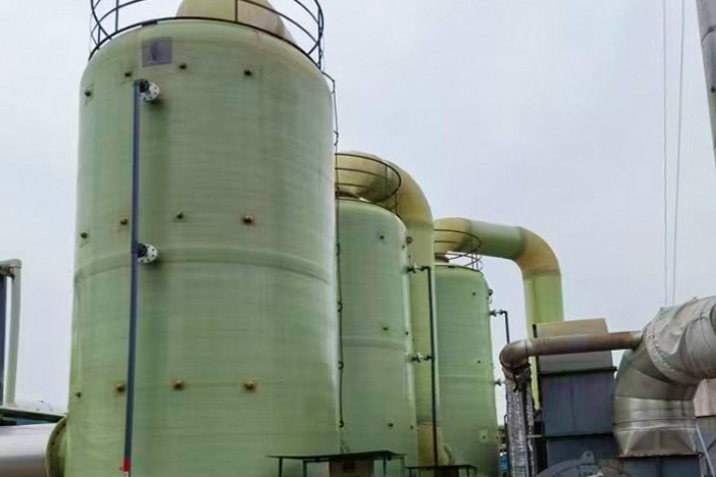
A 3 m diameter FRP tank is emptied by a vacuum truck at the end of a maintenance shutdown. The vent nozzle still carries the plastic cap that was fitted to keep rain out. The pump runs for perhaps forty seconds before the shell flattens along one side with a noise that everybody on site remembers. Nothing leaked, no chemical was released, and the tank is a total loss. The post-mortem usually blames the operator. The real cause is that the tank was bought as a pressure vessel and never designed for external pressure at all.
This is not an unusual story in FRP. Atmospheric tanks are quoted by volume, diameter, resin and wall thickness, and the vacuum case is left as an assumption. For steel the assumption is often harmless because the modulus is high. For FRP it is not: the elastic modulus of a wound or contact-moulded laminate is roughly one twentieth to one tenth that of steel, so the shell buckles at a small fraction of the pressure that would merely stress a steel shell. This guide works through the mechanics that decide whether a tank survives vacuum, the code positions that apply, the arithmetic for a typical vessel, the detailing rules that make a stiffener ring actually work, and the acceptance test that proves it. The companion subjects are covered separately: ASME Section X and RTP-1 certification for the qualification system, seismic restraint and anchorage for lateral loads, and tank covers and odour hoods for the top-side details that a vacuum case loads in reverse.
1. Vacuum Loads a Shell in Compression, Not Tension
Internal pressure puts the shell in hoop tension and the failure mode is a fibre or laminate strength limit, which is why pressure design is about stress, strain and design factors. External pressure puts the same shell in hoop compression, and the failure mode is instability. A cylinder under uniform external pressure does not fail when the stress reaches a strength value. It fails when the geometry can no longer stay round, at a pressure that depends on the wall thickness cubed, the diameter cubed and the unsupported length.
The difference in scale is easy to demonstrate. For a 3000 mm diameter shell with a 12 mm wall under 5 kPa of vacuum, the hoop compression is pD/2t = 0.625 MPa. A vinyl ester laminate in compression can carry 80 to 120 MPa, so the stress utilisation is well under one percent. The same shell, with 6000 mm between lines of support, has an elastic buckling pressure of about 13.3 kPa, which after a design factor of 2.7 is an allowable vacuum of about 4.9 kPa. The strength calculation says the tank is barely working. The stability calculation says it is at its limit.
There is a second consequence that matters on site. At the calculated buckling pressure the shell strain is only about 0.017 percent. There is no cracking, no weeping joint and no visible warning before the lobe forms. The shell goes from round to oval in milliseconds. That is why vacuum protection has to be designed in rather than inspected for.
A tank that is strong enough is not the same as a tank that is stable enough. For FRP under vacuum, the second question is the only one that decides the wall thickness.
2. The Five Vacuum Cases That Actually Occur
Design reviews often record a single line, "full vacuum", or nothing at all. In practice five different events produce five different magnitudes, and the largest is rarely the one that people plan for.
| Event | Typical magnitude | How it develops | What it loads |
|---|---|---|---|
| Pump-out with a blocked or undersized vent | Equals the liquid withdrawal rate, converted to air (API 2000 gives 8.02 SCFH per gpm, effectively 1:1 by volume) | The pump removes liquid faster than air can enter; the headspace pressure falls until the shell buckles or the pump cavitates | Whole shell, top head and the vent nozzle |
| Steam-out, then closed and cooled | 19.0 kPa for 100 C vapour cooled to 30 C in a sealed shell | Steam condenses, the vapour space collapses, and no air can enter because the manway was closed after steaming | Shell, top head, gaskets, manway cover |
| Hot process duty followed by a cold wash or CIP | Proportional to the temperature drop, roughly 0.27 kPa per kelvin for a vapour space at 100 C | Cold liquid or cold rinse water condenses the vapour; the tank is closed for cleaning | Shell and any internal dip pipe |
| Rain or a cold night on a hot shell | 2.87 m3/h for a 30 m3 headspace at a 30 K drop over one hour | Slow contraction, handled easily by a correctly sized vent, but not by a blocked flame arrester | Vent device, not the shell |
| Siphon or gravity drain with the vent closed | Approaches the full static head of the liquid, up to about 100 kPa for a tall tank | A drain line left open below the tank acts as a siphon; the shell sees the equivalent of the liquid column as vacuum | Shell, bottom knuckle, drain nozzle |
The steam-out case deserves emphasis because it produces a vacuum that no atmospheric FRP tank is designed for, and it happens after the process has already stopped. The calculation is simply the ideal gas relation applied to a sealed volume: 101.3 kPa multiplied by (1 - 303/373) gives 19.0 kPa, or about 1.9 m of water column. A tank rated for 5 kPa will buckle long before the shell cools to ambient. The fix is procedural as much as mechanical: open the manway before cooling, or fit a vacuum breaker that cannot be isolated.
The pump-out case is governed by the pump curve, not by the tank volume. A 20 m3/h pump on a 50 m3 tank will pull 20 m3/h of air through the vent, and if the vent is capped the shell sees the pump's suction. The vacuum truck case is worse because the truck's pump is designed to move liquid and air at high volume and will keep pulling until the hose or the shell gives way.
3. What the Codes Give You, and What They Leave to You
There is no single clause that says "an FRP tank shall withstand X kPa of vacuum". Each standard handles external pressure in its own way and at its own level of detail.
| Document | What it says about external pressure | Practical reading |
|---|---|---|
| ASME RTP-1 | Scope covers vessels at pressures not exceeding 15 psig external and/or 15 psig internal above any hydrostatic head (about 103 kPa). Subpart 3A is rule-based design and includes external pressure; Subpart 3B allows stress analysis. Pressure design factors are 10 for sustained loads and 5 for intermittent loads; corrosion barrier strain limits are 0.13 percent (or 0.10 percent for lower-elongation resins) sustained and 0.20 percent intermittent. | The standard does define the load case, and the external pressure rules exist. It does not replace a stability check on a geometry outside the rule envelope, such as a shell with large openings or an unusual ring layout. |
| ASME Section X | Class I and Class II vessels with their own design-by-rules approach, including external pressure. A 1996 ASME Journal of Pressure Vessel Technology test programme on filament-wound cylinders reported that RTP-1 was conservative against the measured buckling pressures, while Section X did not deliver the design factor of 5 that its rules imply. | Do not assume that a nominal factor in a code equals the factor achieved by a particular geometry. Ask for the calculation, not the class label. |
| EN 13121-3 | Above-ground GRP tanks and vessels up to 10 bar and -40 C to +120 C. Clause 9 applies the partial factor method to external actions including inadequate venting; clause 10 gives shell, dished end, flat bottom, skirt, opening and stiffening ring checks, including buckling. Published design examples applying the standard use a minimum overall design factor K of 4 and a minimum buckling factor F of 2.7. | The most explicit European route for a vacuum case. The buckling factor is lower than the pressure factor, which reflects how sensitive buckling is to imperfections rather than an invitation to economise. |
| ADR / UNECE portable tanks, 6.9.4.6 | For the external design pressure, the minimum safety factor against buckling of the shell shall not be less than 5. | A useful benchmark when a client asks for a "transport-grade" margin, even for a static tank. |
| ASME BPVC VIII-1 UG-28 and UG-29 | UG-28 is the external pressure procedure for cylindrical shells (factor A, factor B, allowable pressure); UG-29 sizes the stiffening rings that create the lines of support, including the effective shell band of width 1.1 times the square root of D0 times t. | Not written for FRP, but the mechanics are the same and most FRP designers use this route with a laminate modulus and an FRP-appropriate design factor. |
Two things are left to the designer in every one of these documents. The first is the modulus. FRP is orthotropic: the circumferential modulus of a hoop-dominant wound laminate can be 25 to 35 GPa, while a contact-moulded chopped-strand laminate is nearer 7 to 10 GPa, and the axial modulus is different again. Using the wrong number changes the answer by a factor of three or more. The second is imperfection sensitivity. A shell that is out of round by one percent of its diameter, or that has a flat spot where a nozzle pad was laminated, buckles well below the theoretical value. Codes handle this with the design factor and with tolerances, not with a formula.
4. Screening the Shell: One Formula Before Any FEA
Before a finite element model is justified, a closed-form estimate tells you whether the geometry is in the right range. The Windenburg-Trilling expression, which is the basis of the envelope curves in ASME Section II Part D, gives the elastic buckling pressure of a finite-length cylinder under uniform external pressure:
p_cr = 2.42 E (t/D)^2.5 / [ (1 - nu^2)^0.75 (L/D - 0.45 (t/D)^0.5) ]
where E is the circumferential modulus, t the structural wall thickness (corrosion barrier included only if it is bonded and continuous), D the mean diameter and L the unsupported length between lines of support. The same expression is used in composite pressure vessel work with the laminate modulus substituted for the isotropic value. For very long shells the result must be compared with the long-cylinder limit, 2E(t/D)^3/(1-nu^2), and the higher of the two governs.
| D (mm) | t (mm) | D/t | Elastic p_cr (kPa) | Allowable at F = 2.7 (kPa) | Allowable head of water (mm) | Allowable at F = 5 (kPa) |
|---|---|---|---|---|---|---|
| 2000 | 8 | 250 | 8.8 | 3.3 | 334 | 1.8 |
| 2000 | 12 | 167 | 24.4 | 9.0 | 923 | 4.9 |
| 2000 | 16 | 125 | 50.2 | 18.6 | 1897 | 10.0 |
| 2000 | 20 | 100 | 87.9 | 32.6 | 3320 | 17.6 |
| 3000 | 8 | 375 | 4.8 | 1.8 | 182 | 1.0 |
| 3000 | 12 | 250 | 13.3 | 4.9 | 503 | 2.7 |
| 3000 | 16 | 188 | 27.4 | 10.2 | 1036 | 5.5 |
| 3000 | 20 | 150 | 48.0 | 17.8 | 1813 | 9.6 |
| 4000 | 8 | 500 | 3.1 | 1.2 | 119 | 0.6 |
| 4000 | 12 | 333 | 8.7 | 3.2 | 328 | 1.7 |
| 4000 | 16 | 250 | 17.9 | 6.6 | 675 | 3.6 |
| 4000 | 20 | 200 | 31.3 | 11.6 | 1181 | 6.3 |
All values in the table are for L = 6000 mm, E = 10 GPa and nu = 0.3. The pattern is the useful part. Doubling the diameter from 2000 to 4000 mm at a fixed wall thickness of 12 mm drops the allowable vacuum by a factor of 2.8, because the D/t ratio doubles. Going from 8 mm to 16 mm at 3000 mm diameter raises it by a factor of 5.7, because p_cr scales with t to the power 2.5. Nothing about this is intuitive on a quotation sheet, which is why the calculation belongs in the enquiry and not in the shop drawing.
Two warnings about using the formula honestly. It assumes a perfect cylinder, so a real tank will buckle below the printed value; the design factor is what buys back the difference, which is why a factor of 2.7 is not generous and 5 is the number to use when the consequence of failure is severe. And it assumes an isotropic modulus, so an orthotropic laminate needs either the hoop modulus with an increased factor or a shell-of-revolution buckling analysis. Treat the closed-form result as a screening number: it is accurate enough to decide whether to add a ring, and not accurate enough to release a drawing for a laminate whose hoop and axial moduli differ by more than about 30 percent.
5. Thickness or Rings: The Cost Argument
The first instinct when a tank fails the vacuum check is to thicken the shell. The arithmetic explains why that instinct is expensive. To reach a 5 kPa allowable at 3000 mm diameter with a 6000 mm unsupported length, the calculation needs a structural wall of 12.1 mm, which is a laminate mass of about 23 kg per square metre at a density of 1.9 g/cm3. Adding thickness also adds laminate time, cure time and weight on the foundation, and it does nothing for the head, the nozzles or the manway.
Shortening the unsupported length is far more efficient, because the buckling pressure is inversely proportional to the length term. The same 12 mm shell behaves as follows.
| Unsupported length L (mm) | L/D | Elastic p_cr (kPa) | Allowable at F = 2.7 (kPa) | Allowable head of water (mm) | Critical hoop strain (%) |
|---|---|---|---|---|---|
| 6000 | 2.00 | 13.3 | 4.9 | 503 | 0.017 |
| 3000 | 1.00 | 27.1 | 10.0 | 1022 | 0.034 |
| 2000 | 0.67 | 41.2 | 15.3 | 1555 | 0.051 |
| 1500 | 0.50 | 55.7 | 20.6 | 2105 | 0.070 |
| 1000 | 0.33 | 86.2 | 31.9 | 3256 | 0.108 |
One ring at mid-height, giving a 3000 mm bay, more than doubles the allowable vacuum. Two rings, giving 1500 mm bays, quadruple it. The critical strain column is worth reading twice: even at 20 kPa the shell strain at buckling is 0.07 percent, so the laminate is nowhere near any strength limit and the ring is doing all of the work.
6. Sizing the Ring: Inertia, Not Area
A ring is a line of support only if it is stiff enough to hold the shell round. That is why the sizing quantity is a moment of inertia, not a cross-sectional area. UG-29 uses a factor B and a chart read, but the same requirement can be expressed directly as a ring-buckling check: the ring carries the pressure acting on the shell strip of length Ls, so the required inertia about its own axis is
I_req = F p R^3 Ls / (3 E)
with R the shell radius, p the allowable vacuum, Ls the tributary length of shell and F the design factor. For a 3000 mm tank at 5 kPa allowable, Ls = 1500 mm and E = 10 GPa, this gives 2.28 x 10^6 mm4. A laminated ring alone is nowhere near that, and that is the point most drawings miss.
| Ring section (radial x width) | Area (mm2) | I of ring alone (mm4) | Ratio to I_req | I of ring + 209 mm shell band (mm4) | Ratio to I_req |
|---|---|---|---|---|---|
| 15 x 80 | 1200 | 2.25 x 10^4 | 0.01 | 2.39 x 10^6 | 1.05 |
| 20 x 100 | 2000 | 6.67 x 10^4 | 0.03 | 5.19 x 10^6 | 2.28 |
| 25 x 120 | 3000 | 1.56 x 10^5 | 0.07 | 9.58 x 10^6 | 4.21 |
| 40 x 150 | 6000 | 8.00 x 10^5 | 0.35 | 2.29 x 10^7 | 10.05 |
| 50 x 200 | 10000 | 2.08 x 10^6 | 0.91 | 5.59 x 10^7 | 24.53 |
The composite column is the real structure. UG-29 credits a band of shell of width 1.1 times the square root of D0 times t, which for a 3000 mm shell with a 12 mm wall is 209 mm, and that band sits far from the neutral axis once the ring is laminated onto the outside. A 120 mm wide, 25 mm thick ring provides 4.2 times the required inertia as a composite, but only 7 percent of it as a bare ring. The ring is not a stiffener in its own right; it is a device for mobilising a band of shell. That has a direct consequence for fabrication: a ring that is spot-bonded, bonded over a dirty surface or interrupted at a nozzle does not mobilise the band, and the calculation that justified it is void.
7. Detailing Rules for FRP Rings
The geometry is settled by the calculation; the details decide whether the calculation applies. The following rules are the ones that come back in failure investigations.
- Continuous around the full circumference. No butt joints, no overlaps stopped short at a nozzle. Where a nozzle or manway interrupts the ring, replace the interruption with a collar of at least the same section, laminated to both sides of the opening.
- Bond width and taper. A minimum of 50 mm of bonded width on each side of the ring foot, with the overlay tapered at 1:6. A square edge at the ring toe is a stress raiser and a place for the overlay to peel under repeated vacuum cycles.
- Surface preparation before bonding. Grind to fresh laminate with 36 grit, remove dust, wipe with a solvent that the resin system accepts, and laminate within the resin's open time. A ring bonded onto a release-agent-contaminated or wet surface will pass a tap test when new and fail two years later.
- Ring on the outside or the inside. An external ring is easier to inspect and does not trap product, but it creates a water trap at its lower edge on an outdoor tank and interrupts insulation. An internal ring is protected from weather but traps solids in slurry service and is harder to inspect. Neither choice changes the inertia requirement.
- Do not laminate a ring across a shell joint. Stagger the ring at least 100 mm from any circumferential seam, or laminate the seam first, post-cure, and then apply the ring.
- Watch the material of the ring. A pultruded profile bonded to a wound shell has a different fibre architecture and a different coefficient of thermal expansion in the through-thickness direction. Use a laminated ring of the same resin system where the tank cycles in temperature, or design the bond for the differential movement.
- Weep holes and drainage. An external ring on an outdoor tank needs a small weep hole at its lowest point, or the trapped water will find the bond line. An internal ring needs a gap or a scallop at the bottom so that the tank drains completely.
A ring that is not continuously bonded is not a line of support, whatever the drawing says. The calculation assumes composite action; the laminate schedule has to deliver it.
8. Heads, Flat Tops, Nozzles and Manways
The shell is usually the first thing checked and the last thing that fails. In practice the top of the tank is more vulnerable, because a flat or slightly conical top is a plate in bending under the same vacuum, and its span is the full diameter.
A dished head carries external pressure in membrane compression and is normally satisfactory if the knuckle is thick enough and the head is not too flat. A flat top designed for walkway loads and snow is a different structure: a 6 mm flat cover over a 3 m span has a bending stiffness that is negligible compared with the shell, and it will deflect visibly at a few kPa. Flat tops need beams, a self-supporting conical section with a steep angle, or a dedicated ring at the top. If the top is removable, the gasket and the fixings become part of the vacuum boundary, and vacuum pulls the cover into the tank rather than off it, which is the opposite of the load case the fixings were designed for.
Nozzles fail in a way that is easy to overlook. A thin-wall nozzle under external pressure is a short tube in compression, and it can ovalise at a lower pressure than the shell because its diameter-to-thickness ratio is higher and its length between the shell and the flange is short enough to buckle in an oval mode. Two rules follow. First, the nozzle neck should be at least as thick as the shell it penetrates, and thicker for sizes above DN200. Second, the reinforcement pad or the overlay around the nozzle must be designed for the vacuum case as well as the pressure case, because the pad is also a local stiffener that interrupts the shell's curvature.
Manways are the largest opening and the easiest path for a vacuum failure to start. A 600 mm manway in a 12 mm shell removes a significant arc of the compression ring, and the cover is a flat plate on a gasket. Use a confined gasket or an O-ring in a groove so that the seal is not dependent on bolt preload alone, and check the cover plate for the vacuum case rather than only for pressure. In a tank that is routinely steamed, the manway is also the vent that saves the shell, so the operating procedure should require it to be open during cooling.
9. Venting: Sizing the Device That Prevents All of This
Vacuum protection is cheaper than vacuum resistance, and it is the first thing to specify. API 2000 treats the inbreathing requirement from liquid withdrawal as 8.02 standard cubic feet per hour per gallon per minute, which works out to almost exactly one cubic metre of air per cubic metre of liquid. In other words, the vent has to pass the pump rate, and the pump rate is the number that should appear on the datasheet.
| Pump-out rate (m3/h) | Equivalent (gpm) | API 2000 inbreathing (SCFH) | Air volume (m3/h) | Bore at 20 m/s (mm) |
|---|---|---|---|---|
| 5 | 22 | 177 | 5.0 | 9.4 |
| 10 | 44 | 353 | 10.0 | 13.3 |
| 20 | 88 | 706 | 20.0 | 18.8 |
| 40 | 176 | 1412 | 40.0 | 26.6 |
The bore column is a screening value at an air velocity of 20 m/s, where the dynamic head is only about 240 Pa, so the pressure drop across a clean vent is negligible compared with a 5 kPa vacuum allowance. That margin disappears as soon as the vent is fitted with a flame arrester, a bird screen, a filter or a long horizontal run. A blocked flame arrester is the single most common cause of tank collapse in chemical plants, because it is designed to be restrictive and it fouls silently. Size the device for at least twice the calculated inbreathing when any of those elements are present, and put the arrester on a cleaning schedule with a recorded pressure drop.
The device itself should be a weight-loaded or spring-loaded pressure/vacuum relief valve sized for the inbreathing rate, set to open above the tank's rated vacuum and below the pressure at which the shell buckles with the design factor applied. A tank rated for 4 kPa should not carry a valve set at 8 kPa. For tanks that are steamed, a second, independent vacuum breaker on the vapour line is worth the cost, because the relief valve may be isolated with the line it protects. Never rely on the manway, the dip pipe or a loose cover as the vacuum path.
10. Acceptance: The Vacuum Test and Its Record
The design is only proven by a test that reproduces the load. A hydrostatic test proves the shell in tension and says nothing about stability. The vacuum test is a separate acceptance step, and it should be written into the purchase order with the same detail as the hydrotest.
| Item | Recommended requirement | Why |
|---|---|---|
| Test pressure | Design vacuum, applied at not more than 1 kPa per minute | Rate control avoids a dynamic overshoot and lets the shell settle between increments |
| Hold time | 60 minutes at design vacuum after stabilisation | Creep and joint bedding show up as drift in the first minutes, not as an instant failure |
| Instrumentation | Vacuum gauge with 0.1 kPa resolution, calibrated; dial gauges or a total station at mid-bay, at each ring and on the head | A compound gauge at a quarter of its scale cannot resolve 0.2 kPa, and deflection is the early indicator |
| Acceptance | No audible or visible lobe formation; no whitening or crazing at ring toes or nozzle pads; permanent radial deflection after release not more than 0.2 percent of diameter | Whitening at a ring toe is the first sign that the bond is not carrying the shell band |
| Leak check | Pressure decay not more than the allowance for the test volume and temperature drift, with the temperature recorded at the start and end | A sealed tank changes pressure with ambient temperature; without the temperature the decay number is meaningless |
| Record | Gauge identification, start and end temperature, vacuum trace, deflection readings by location, photographs of every ring toe and nozzle pad | The record is what an insurer and a future inspector will ask for, and it is cheap to produce at the time |
The test sequence should be: complete all lamination and post-cure, spark-test any thermoplastic lining, fit the permanent rings and nozzle pads, then apply vacuum in steps of about 1 kPa with a deflection reading at each step. If a lobe appears, stop, release the vacuum and inspect. Do not laminate over a buckled lobe and call it repaired; the fibres in the lobe are already separated from the shell and the geometric imperfection remains. Cut out the affected band, re-laminate it with a proper overlay and add a permanent ring at the location, then repeat the test.
For critical service, acoustic emission monitoring during the hold adds a second channel of evidence. The technique detects fibre breakage and delamination as they happen, which is exactly the failure mode that a vacuum test provokes, and it is already used for FRP vessels under ASTM E1067. It does not replace the deflection readings; it tells you whether the shell was complaining while the dial gauges were steady.
Write the Vacuum Case Before the Drawing
The cheapest vacuum protection is a line in the enquiry: maximum vacuum, source of vacuum, pump-out rate, steam-out temperature, and whether the tank will ever be closed while hot. With those four numbers a fabricator can run the screening calculation, decide between thickness and rings, size the vent and write a test that proves the result. Without them, the tank is designed for the only load case that was written down, and the site finds the other one.
For the hardware side, the vertical chemical service tank range is here: FRP vertical storage tank for chemical service, with the wound horizontal range at filament-wound horizontal storage tank and the agitated and mixing duty version at FRP chemical mixing tank.
Related reading: ASME Section X and RTP-1 certification for the qualification route behind the design factors, seismic restraint of FRP tanks for the other load case that sizes the base ring, tank field erection and post-cure for the joints that the ring must not cross, tank covers and odour hoods for the top-side structure under reverse pressure, the vertical tank guide for foundations and wind, and chemical tank safety for venting and bunding in the wider sense.
Need help selecting FRP products?
Our engineers answer technical questions free of charge.
Ask an Engineer on WhatsApp