
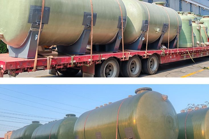
Insulation on a steel tank is a heat-loss problem. Insulation on an FRP tank is a heat-loss problem plus a material-limits problem, and the second one is where projects go wrong. A vinyl ester tank that has given fifteen years of service storing hydrochloric acid at ambient temperature can be destroyed in a single winter by a heat-tracing cable sized the way it would have been sized for a steel vessel: the same watts, spread over a wall that conducts heat 170 times more slowly, produce a local wall temperature far above anything the resin was ever cured to survive.
This guide covers the four things an FRP tank insulation and tracing specification has to fix together: the resin temperature ceiling, the insulation material, the thickness that satisfies the governing criterion, and the power density that keeps the shell below its limit. All four are interdependent, and the numbers below are the ones procurement arguments usually hinge on.
1. Four Different Jobs, Four Different Governing Criteria
Insulation is sold by thickness, but thickness is not the specification — the governing criterion is. An FRP tank wrapped to 25 mm for personnel protection will freeze solid in a northern winter; a tank wrapped to 100 mm for freeze protection will fail a corrosion-under-insulation inspection on a coastal site because nobody specified the cladding. Decide which of these you are actually buying:
- Freeze protection. The criterion is hold time: how long the contents can sit stagnant at the design minimum ambient before reaching the critical temperature. Driven by insulation, thermal mass and tracing power together.
- Process temperature maintenance. A setpoint, usually 10–40 °C, must be held. The criterion is the balance between heat loss and traced heat input at the coldest ambient.
- Condensation control (cold service). The criterion is that the outer surface stays above the ambient dew point with a margin, which means a continuous vapour barrier — not extra thickness.
- Personnel protection and energy. The criterion is a maximum touchable surface temperature, typically 45–60 °C depending on contact duration, and/or an economic thickness.
The mistake is specifying one criterion and assuming the others come free. They do not, and on FRP the freeze-protection case is usually the one that also decides the heater power density — which is the number that can kill the tank.
Rule of thumb for FRP vessels: insulation thickness is driven by the thermal duty, but the heat-tracing power density is driven by the resin limit. Size the tracer to the wall, not to the heat loss, and then verify the heat loss can still be met.
2. Start With the Shell: What Temperature the Resin Can Actually Take
The resin system, not the glass, sets the temperature ceiling. Published heat distortion temperatures (HDT) and the practical continuous service temperatures used in chemical service diverge significantly, because chemical attack, hydrolytic degradation and creep all accelerate as the laminate approaches its glass transition.
| Resin system | Typical HDT | Practical continuous service in chemical duty | Notes for traced or insulated service |
|---|---|---|---|
| Orthophthalic polyester | 65–85 °C | 45–55 °C | Water, cooling towers, neutral salt solutions. Not for traced hot chemical service. |
| Isophthalic polyester | 90–110 °C | 65–80 °C | Acceptable ceiling with elevated post-cure; good cost/performance for warm water and dilute acids. |
| Bisphenol-A vinyl ester | 100–120 °C | 80–95 °C | The workhorse for traced chemical tanks; ceiling rises with a proper post-cure. |
| Novolac / high-performance vinyl ester | 130–140 °C | 110–120 °C (media dependent) | Where hot oxidising acids or solvents force a high ceiling — verify against the resin supplier's chemical resistance table at the actual temperature. |
Two consequences follow immediately. First, a resin selected for the chemistry at 60 °C is not automatically suitable for the same chemistry at 85 °C — corrosion resistance is a temperature-dependent property, and most chemical resistance charts are published at discrete temperatures (20/40/60/80 °C) precisely because of this. Second, the wall temperature during tracing is what matters, not the fluid setpoint. A tank holding 40 °C liquid with a mis-applied tracer can easily have a local wall temperature above 100 °C.
Thermal conductivity: the number that makes FRP different
E-glass/polyester and E-glass/vinyl ester laminates have a thermal conductivity of roughly 0.3–0.7 W/m·K (about 2.1 Btu·in/hr·ft²·°F for a typical chopped-strand laminate). Carbon steel is about 50 W/m·K and aluminium about 205 W/m·K. An FRP wall therefore conducts heat roughly 150–200 times more slowly than steel.
That sounds like an advantage — and it partly is, since the shell itself is a modest insulator. But it also means external heat does not spread. Heat applied to a 12 mm FRP wall in a 100 mm spot stays in a 100 mm spot, because there is no lateral conduction path to carry it away. On a steel vessel the same defect is invisible; the steel simply redistributes the heat. On FRP it becomes a local hot spot, with the resin on one side of the wall and the liquid on the other acting as an inefficient heat sink.
The expansion coefficient has the same practical consequence: FRP moves 1.0–2.5 × 10⁻⁵ per °C depending on laminate build-up, roughly two to four times the movement of steel. Insulation cladding and support details must therefore be free to move with the shell and must never be used to brace it.
3. Choosing the Insulation Material for an FRP Substrate
Because an FRP shell rarely sees hot-face temperatures above 120 °C, almost every industrial insulation material is thermally acceptable. The selection is therefore driven by water, fire performance, mechanical robustness and access — in that order.
| Material (ASTM spec) | k at ~25 °C | k at ~100 °C | Max service | Water behaviour | Where it wins on FRP tanks |
|---|---|---|---|---|---|
| Mineral / rock wool lamella (C547, C592) | 0.033–0.040 | 0.040 | 650 °C | Absorbs water; needs cladding and vapour control | Default for hot or traced service; non-combustible, cheap, tolerant of movement |
| Glass wool (C547 Type I) | 0.032–0.037 | 0.038 | 450 °C | Absorbs water | Light, low cost where the shell stays below 100 °C |
| Cellular glass (C552) | 0.040–0.047 | 0.051 | 430 °C | Zero absorption, closed cell | Cold service, washdown areas, buried sections, load-bearing saddle inserts |
| Polyisocyanurate / PUR (C591) | 0.023–0.028 | — | 110–150 °C | Closed cell; insulated faces needed | Thin build-ups on cold or chilled tanks; check the maximum service temperature against the shell temperature |
| Elastomeric foam (C534) | 0.033–0.040 | — | 105 °C | Closed cell, own vapour retarder | Small tanks, nozzles and irregular shapes where a flexible, self-sealing wrap is worth the price |
| Aerogel blanket (C1728) | 0.014–0.020 | 0.020 | 650 °C | Hydrophobic, breathable | Space-constrained retrofits where 15 mm must do the work of 40 mm |
Three FRP-specific cautions:
- Water is the real enemy, not heat. An absorbent insulation that gets wet does two things at once: its conductivity rises toward that of water (0.6 W/m·K), destroying the thermal performance, and it holds a wet layer against a warm laminate. On FRP the resulting attack is hydrolytic — resin breakdown, fibre exposure and blistering — rather than the steel-wall pitting we call CUI. The design response is the same though: keep water out with a continuous cladding and, on cold service, a continuous vapour barrier.
- Fire performance should not be downgraded by the insulation. An FRP tank carrying a Class 1 flame-spread laminate should not be wrapped in a combustible foam without checking how the assembly performs as a system.
- Design for removable access. Manways, level instruments, sample points and agitator flanges need insulation that comes off and goes back on: reusable blankets or lidded boxes at every penetration, rather than a cut-and-stuff detail that is never reinstated correctly.
4. Calculating the Thickness: One Criterion Governs
Thickness is resolved with a steady-state conduction model — the established practice is ASTM C680 for flat, cylindrical and spherical systems, or ISO 12241 for insulation systems generally. The reason those standards exist in software form is that the solution is iterative: the outer surface temperature determines the convection coefficient, and the convection coefficient determines the outer surface temperature.
A first-order estimate for surface-temperature control is the standard balance between conduction through the insulation and convection/radiation from the surface, which rearranges to:
X = (k / h) × (Thot − Tsurf) / (Tsurf − Tamb)
X = insulation thickness (m) · k = thermal conductivity at mean temperature (W/m·K) · h = combined surface coefficient (W/m²·K) · T = temperature (°C)
Apply it to a real case. A vertical FRP tank, 2.4 m diameter, 3 m shell height, holding 80 °C process water in a 20 °C plant, with a combined surface coefficient around 10 W/m²·K:
- Bare shell loss: roughly 1,000 W/m² at a 60 K temperature difference. On a shell plus bottom area of about 27 m² that is on the order of 27 kW of continuous heat loss — enough to matter financially, and enough to make the plant uncomfortable in summer.
- With 50 mm mineral wool (k = 0.040 at a mean of about 50 °C): the conduction resistance is 0.050/0.040 = 1.25 m²·K/W, the surface resistance is 0.1 m²·K/W, so the flux is 60/1.35 ≈ 44 W/m² and the outer surface settles near 24 °C. Total loss falls to about 1.2 kW.
- That is a reduction of over 95%, or roughly 200 MWh per year at 8,000 operating hours. Insulation of this class typically pays back in well under two years on energy alone.
Now check the personnel-protection criterion with the same numbers. To keep the surface at or below 45 °C by calculation alone, the required thickness would be only (0.040/10) × (80−45)/(45−20) ≈ 0.006 m. In other words, on this tank the touch-temperature criterion is almost irrelevant — the energy criterion governs, and 50 mm is chosen for economics and mechanical robustness, not for safety. This inversion is common on warm FRP tanks and it is worth stating explicitly in the specification, because it explains why "the surface is only 25 °C, so we could have used less" is the wrong conclusion.
The opposite happens in cold service. A chilled tank whose surface runs below the ambient dew point will condense water continuously regardless of how much energy it saves, so the criterion becomes surface temperature above dew point with a 1–2 K margin, plus a vapour barrier that is genuinely continuous. Closed-cell materials (cellular glass, PIR, elastomeric) are the right family there; an open-cell wool with a perfect aluminium jacket is still one unsealed lap away from a soaked, useless layer.
5. Heat Tracing Options and Their FRP Ceilings
There is a hard distinction between heating a tank and heating a tank wall. Raising the bulk temperature of 20 m³ of liquid through a wall that conducts 0.3 W/m·K is a losing proposition — you will either never get there or you will cook the laminate trying. Bulk temperature rise belongs to immersion heaters, external heat exchangers or coil circuits. External tracing is for maintaining a temperature or preventing freezing, and it should be designed as such.
| Method | Typical output | Practical maintain temperature | Control | Fit with an FRP shell |
|---|---|---|---|---|
| Self-regulating electric cable | 10–30 W/m at 10 °C | ~65 °C, with intermittent exposure limits around 85 °C | Inherently self-limiting by temperature; thermostat optional but recommended | Best general choice. Fluoropolymer-jacketed cable for corrosive plant. Must be separated from bare laminate by a heat-spreading layer. |
| Tank heater pads / panels | ~0.6 W/in² (≈ 930 W/m²) on low-power plastic-rated models | Depends on wall temperature rise — see §6 | Integrated over-temperature thermostat | Viable on FRP only at low power density and with the wall temperature verified. High-density metal-tank pads are not suitable. |
| Constant-wattage cable | Higher, cable-dependent | Set by thermostat | Line-sensing thermostat mandatory | Use with care: no self-limiting behaviour, so a single control failure can overheat a local area. |
| Steam or hot-oil tracing | Very high at the trace | Steam line temperature | Steam trap and control valve | Generally avoided. A 150 °C trace tube against a laminate whose ceiling is 90 °C is a defect waiting to happen unless there is a robust air gap and a monitored surface temperature. |
| Jacket with hot-water or hot-oil circulation | Low flux, large area | 60–95 °C | Supply temperature control | Gentle and uniform — the most forgiving electric-free option for large tanks, if the shell was designed for a jacket load. |
| Immersion heater / external heat exchanger | kW-class | Process driven | Process controller | The correct method for bulk heating. Keeps the heat source away from the laminate entirely. |
6. Power Density: The Calculation That Keeps the Shell Alive
The wall temperature rise produced by a heater applied to a plastic wall follows directly from conduction through the wall:
ΔTwall = Qa × t / k
Qa = heater power density · t = wall thickness · k = wall conductivity
Worked in the units these design guides are written in: a 0.6 W/in² heater pad on a ½ inch (12.7 mm) FRP wall. With Qa = 295 Btu/ft²·hr and k = 2.1 Btu·in/hr·ft²·°F for FRP, the wall gradient is (295 × 0.5) / 2.1 ≈ 94 °F (about 52 K) on top of the fluid temperature and the fluid-side film gradient.
So a tank of 50 °F water traces to an outer wall temperature around 154 °F (68 °C) — acceptable. The same pad on a tank holding 150 °F fluid would drive the wall to roughly 254 °F (123 °C), well past the ~220 °F (104 °C) limit commonly quoted for FRP tank walls and past the practical ceiling of most vinyl esters. Nothing about the heater changed; only the starting temperature did. This is why a heat-tracing design cannot be copied from one tank to another without re-running the arithmetic.
The trap is that self-regulating cables deliver their highest output when they are coldest, which is exactly the freeze-protection scenario they are bought for. The design must be checked at the coldest fluid condition, not the warmest.
Practical rules that follow from the calculation:
- Cap the power density at the value the tank supplier will accept for the specified wall thickness — typically the plastic-rated 0.6 W/in² class rather than a metal-tank heater.
- Spread the heat. Aluminium foil tape or a thin heat-distribution plate between the cable and the laminate increases the effective contact area and flattens the gradient. Never let a cable sit directly against bare FRP with no spreading layer.
- Use more cable at lower output rather than less cable at higher output. Longer runs at 10 W/m beat short runs at 30 W/m on every FRP tank.
- Sense the shell, not the air. The thermostat must read the laminate surface, with the setpoint at least 5–10 K below the resin ceiling, plus an independent high-temperature alarm.
- Verify, do not assume. After commissioning, measure the actual wall temperature with a contact probe or thermal camera with the tracer at full duty and the fluid at its coldest, and record it as the baseline.
7. Supports, Nozzles and Thermal Bridges
On a small tank the supports can dominate the loss. Steel saddles, ring supports and skirt connections are highly conductive paths straight through the insulation, and a tank whose insulation is perfect except at three saddles still loses a substantial share of its heat there.
- Support saddles. Insulate between the shell and the support wherever the design allows, using a load-bearing insulation with real compressive strength — cellular glass or a high-strength calcium silicate block — instead of letting steel touch the laminate. Confirm the insert's allowable bearing stress with the tank designer; this is a structural decision as well as a thermal one.
- Nozzles, manways and instrument connections. Insulate them, but never insulate over a flange face or a bolted cover. Use reusable blankets or purpose-made lidded boxes so the connection can be broken and remade without destroying the insulation. Every reinstated access detail should be treatable as a hot-work-free, hand-fitted item.
- Level gauges and sight glasses. These are usually the point where the vapour barrier is first breached. Detail them deliberately, with a sleeve or a jacket, and record the detail on the insulation drawing.
- Cladding. 0.5–0.6 mm aluminium is the default; in a chloride or acid plant use 0.5 mm 316 stainless, and inspect it for staining as a corrosion indicator. Laps must shed water: horizontal runs lap downwards, vertical runs lap away from the prevailing wind, and insulation expansion joints are needed on long runs and wherever the cladding would otherwise be restrained by the tank's own growth.
- Never brace the shell with the cladding. With FRP expanding 1.0–2.5 × 10⁻⁵ per °C, a cladding fixed rigidly to both the shell and a fixed structure will either tear itself or load the shell.
8. Installation and Quality Control
The thermal model assumes a system, and the system is only as good as the installation. The checks that matter on an FRP tank:
- Multi-layer insulation with staggered longitudinal and circumferential joints — never line up joints through the full build-up, because that creates a direct thermal path.
- Correct density and fit. Lamella or wired mat installed with a compressed, over-tight closing panel loses thickness and performance.
- Dry materials. No insulation is installed over a wet shell, wet insulation, or in rain without a temporary shelter detail.
- Continuous vapour barrier on cold service, verified at every penetration, with a repair procedure agreed before work starts.
- Cladding lap direction verified, and fasteners that do not penetrate the vapour barrier on cold service.
- Distance from any hot surface, and no insulation material installed outside its rated service temperature range.
- Thickness verification with a needle or thermal gauge at documented locations, recorded against the drawing.
- Thermal-imaging baseline after 48 hours of steady operation, kept as the reference for the next inspection.
The insulation system should also be documented as a system: material, thickness, density, cladding, tracing layout, thermostat setpoints and alarm values, plus the manufacturer's data sheets. When the tank is inspected in five years, that file is what makes the inspection meaningful.
9. Controls, Monitoring and Electrical Protection
Tracing is electrical work and belongs in an electrical enclosure with its own protection philosophy:
- Ground-fault protection on the tracing circuits, sized to the circuit type, plus the commissioning insulation-resistance test specified by the cable manufacturer.
- At least two shell-mounted temperature sensors on a large tank, so one sensor can fail without leaving the duty unmonitored.
- Independent over-temperature alarm, tested at commissioning and annually, set below the resin ceiling — not below the comfort setpoint.
- Separate minimum and maximum setpoints where the tank has both a freeze duty and a warm-weather standby, since the same cable will behave differently at both ends of the year.
- A hazardous-area classification review before specifying cable, junction boxes and thermostats. Flammable or solvent-bearing service drives ATEX/IECEx-rated components and affects enclosure placement.
Log surface temperatures, ambient temperature and tracing duty cycle. A rising duty cycle at constant ambient is the first symptom of wet insulation; a falling duty cycle on a self-regulating circuit often means the cable has delaminated from the shell, not that the tank has become thermally efficient.
10. Cold-Service Specifics: Condensation, Ice and Chilled Storage
Below-ambient service inverts the whole problem: the enemy is water arriving from outside, and success depends on vapour control rather than conductivity.
- Calculate the dew point for the actual design ambient — the worst combination of high humidity and high temperature, not the annual average.
- Design the surface temperature to sit above the dew point with margin, then size the vapour barrier to be continuous, not merely present.
- Use closed-cell insulation. On washed-down or intermittently wet decks, cellular glass with a stainless jacket is the material that tolerates a jacket breach without soaking up water.
- For freeze protection of an outdoor tank, calculate hold time from thermal mass: the volume of liquid, its specific heat, the insulation resistance and the coldest multi-day ambient, then decide whether tracing is required or whether draining and a small circulation loop is the cheaper answer. This is the same trade-off that governs tower basins and exposed water lines in cold climates.
11. Specification and RFQ Checklist
Give the supplier this information and the sizing can be verified rather than guessed:
| Category | Information to supply |
|---|---|
| Vessel | Diameter, shell height, orientation, wall thickness, laminate build-up, resin system and post-cure schedule |
| Service | Fluid, concentration, minimum and maximum temperature, specific gravity, ventilation, chemical resistance table temperature basis |
| Site | Minimum and maximum ambient, wind speed, indoor/outdoor, design humidity and dew point, washdown frequency, hazardous area classification |
| Insulation | Material and standard, thickness, density, cladding material and gauge, vapour barrier requirement, fire performance of the assembly |
| Tracing | Method, output per metre or per m², voltage, sheath material, maximum maintain temperature, control thermostat type, alarm setpoints |
| Access | List of every penetration requiring removable insulation, flange sizes, frequency of access |
| Acceptance | Target surface temperature, allowable heat loss, thickness verification, thermal imaging baseline, documentation package |
12. Common Mistakes
- Copying a steel-tank tracing layout onto an FRP vessel without recalculating wall temperature rise.
- Specifying insulation thickness for personnel protection on a warm tank where the energy criterion genuinely governs.
- Using open-cell insulation on cold or washdown service and relying on the jacket alone.
- Insulating the shell perfectly and leaving steel saddles as direct thermal bridges.
- Insulating over nozzle flanges and manway covers so that the fastest, cheapest inspection in the plant becomes a destructive one.
- Setting the high-temperature alarm at the process setpoint rather than below the resin ceiling — the alarm then never protects anything.
- Assuming an orthophthalic or isophthalic laminate that resists a chemical at 40 °C will resist it at 80 °C.
- Fastening cladding rigidly to both the shell and the structure, then wondering why the joints open in summer.
Get FRP Tanks Insulated and Traced Correctly
HuanGang supplies filament-wound and contact-moulded FRP storage tanks engineered for traced and insulated service, with the resin system, wall thickness and post-cure schedule documented so that the insulation and tracing design can be verified against the shell limits rather than assumed. Send us your fluid, temperature range, ambient conditions and site classification, and we will come back with the resin system, the laminate schedule and the temperature ceiling your insulation contractor has to design within. Tell us the service and we will tell you what the tank can take.
Related reading: horizontal FRP storage tanks, vertical FRP storage tanks for chemical service, filament-wound FRP chemical storage and mixing tanks, resin selection for chemical equipment, gel coat and corrosion barrier liner design, tank field erection and on-site post-cure, nozzle and manway design and winterisation and freeze protection.
Need help selecting FRP products?
Our engineers answer technical questions free of charge.
Ask an Engineer on WhatsApp