
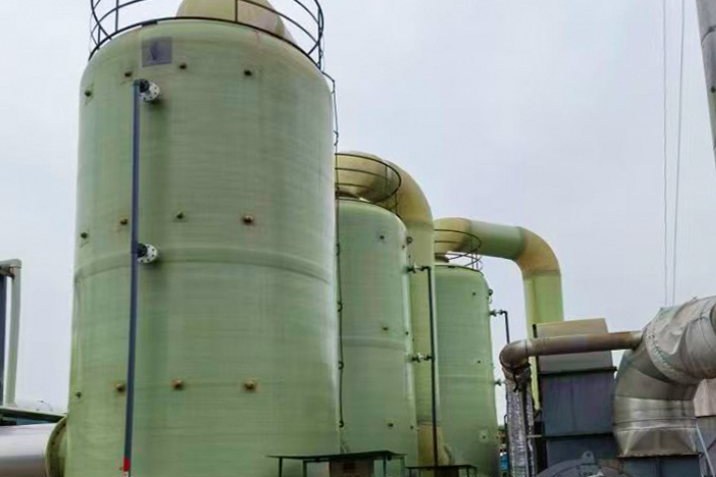
An overfilled tank does not fail politely. The liquid goes over the shell, into the bund or across the dike road, and everything that happens next — fire, pollution, lost product, lost licence — was decided months earlier, when someone chose the level instruments, drew the vent and wrote the alarm setpoints. That is the premise of API 2350, the overfill-prevention recommended practice written after the Buncefield disaster, where a UK terminal tank overfilled in 2005 behind a gauging system that had already failed repeatedly without anyone treating the failures as a pattern.
FRP and GRP tanks add their own twist: the vessels are corrosion-proof but the instruments usually are not, and a nozzle that would shrug off a steel instrument bracket may need reinforcement before it carries anything. This guide walks the whole chain — gauge selection for corrosive service, the independent high-high sensor, the setpoint stack with real numbers, and the FRP-specific installation rules — using the same 3.0 m diameter, 4.0 m liquid level tank as our hydrotest article so the two can be read together.
1. The Language of Levels: CH, HH, MW and Response Time
API 2350 defines three "levels of concern" (LOCs), and it is worth learning them precisely because every setpoint conversation on site drifts without them:
- CH — Critical High: the level at which overflow or damage occurs. Physically, this is set by the vent inlet, the roof low point or any nozzle penetrations above the operating range. No alarm is placed at CH — by the time it sounds, the event is underway.
- HH — High-High: the only alarm the standard actually requires. It is the last automatic chance: when it fires, the response time clock starts.
- MW — Maximum Working level: the highest level reached in normal operation. Everything between MW and HH is margin, and the size of that margin is not a guess — it is your response time multiplied by your fill rate.
The arithmetic is blunt. The vertical distance between HH and CH must be at least:
Margin = rise rate × response time + signal and valve-closure allowance
Rise rate is fill rate divided by tank free-surface area. Response time is the time the whole chain — sensor, alarm, human or interlock, valve — needs to actually stop the inflow. API 2350 lets each facility calculate its own response time, but publishes default minima by equipment category, and those defaults are the backbone of Section 3.
2. API 2350 Categories: What Your Hardware Says About Your Margin
API 2350 sorts tank installations into categories by how level is monitored and how an alarm reaches someone who can act. The categories trade hardware against time:
| Category | Gauging and alarms | Who stops the fill | Default response time (if not calculated) |
|---|---|---|---|
| 0 | Manual measurement, fully locally attended | Person at the tank | 60 min |
| 1 | Assisted operation, local reading | Person at the tank | 45 min |
| 2 | Level and alarm transmitted to a control centre (alarm depends on the automatic tank gauge) | Operator, remotely | 30 min |
| 3 | As Category 2, plus an independent high-high alarm | Operator, remotely — with a second sensor watching | 15 min |
The independent high-high is the whole point of Category 3: a second sensor, powered and wired separately from the primary gauge, so that the failure mode "gauge dies silently" no longer hides a rising level. Where an Automatic Overfill Prevention System (AOPS) is fitted, it must be independent of the basic process control system and act without a human in the loop — and for new installations, API 2350 points to IEC 61511 for that safety instrumented function: define it in a Safety Requirement Specification, assign a SIL target from consequence analysis, and proof-test it on a documented interval. The standard also caps the interval for LOC review at five years, and forces a review under management of change whenever the tank, the product, the flow rates, the gauging equipment or the staffing changes.
3. Choosing the Primary Gauge for Corrosive Service
On a steel tank you would pick an instrument by accuracy and custody-transfer needs. On an FRP tank in acid, brine or solvent service, the first filter is survival — of both the wetted parts and the transmitter electronics living in the vapour space. The usual families, in the order they get specified:
| Technology | Wetted parts | Corrosive-service behaviour | Typical role in the chain |
|---|---|---|---|
| Non-contact radar (through-air or lens antenna) | None | Immune to the medium; only the antenna face and flange gasket see the vapour — spec PTFE or PVDF there | Primary level transmitter; also a natural choice for the independent HH sensor |
| Magnetic level gauge (magnetic float in a chamber, follower outside) | Chamber + float; PTFE/PVDF-lined or exotic-alloy options | Excellent local indication with zero electronics at the tank; float is the lifetime-limiting part | Local display and a robust, independent alarm switch on the chamber |
| Hydrostatic / diaphragm seal transmitter | Seal diaphragm + capillary fill | Chemistry lives in the diaphragm choice; capillaries hate sunlight and snagging | Budget-friendly level signal; watch zero drift with temperature |
| Ultrasonic | None | Non-contact, but foam, vapour saturation and condensation scatter the echo — unreliable on many chemical duties | Non-critical duties only on FRP chemical tanks |
| Servo / ATG gauging | Displacer wire and drum | Highest measurement class; overkill unless inventory accuracy pays for it | Inventory / custody applications |
Two FRP realities steer the choice. First, vapour-space corrosion kills electronics: a transmitter clamped inside an HCl-laden headspace dies young, so non-contact radar or a magnetically coupled gauge wins by default. Second, anything that hangs off the tank is a nozzle load and a laminating decision — Section 7 covers what that means structurally.
4. The Independent High-High: Sensor Choice and Separation
The independent HH sensor must not share a failure mode with the primary gauge. Practical rules that hold up in audits:
- Different principle where feasible: radar primary + magnetic-gauge switch, or radar primary + hydrostatic HH. Two identical radars are better than one, but they share antenna-fouling and condensation failure modes.
- Different nozzle, different penetration — and physically separated so that one splash, one fire or one dropped scaffold pole does not reach both.
- Independent power and routing: the HH loop stays alive when the DCS cabinet is off, and its cable tray does not share a raceway with the primary signal.
- Alarm logic that does not depend on the BPCS: the HH trip belongs in a hard-wired or SIS-grade path. If it merely re-announces in the same screen as the primary, you own a Category 2 installation that looks like Category 3.
- Proof-test it: water-side simulate the trip at commissioning and on a documented interval thereafter. An untested HH switch is a decoration with a terminal block.
For the small tanks common in chemical distribution, a magnetic level gauge with a reed-switch or magnetostrictive HH switch is often the cleanest independent sensor: no electronics in the vapour, a display the operator can trust at the fence line, and a switch that trips on physics rather than firmware.
5. Setting the Numbers: A Worked Setpoint Stack
Take the example tank: 3.0 m diameter, free-surface area 7.07 m², vent inlet at 4.50 m (so CH = 4.50 m), Category 3 installation, maximum fill 8 m³/h. Rise rate = 8/7.07 = 1.13 m/h.
| Setpoint | Level | Margin below the next level above | Basis |
|---|---|---|---|
| CH (Critical High) | 4.50 m | — | Set by vent inlet; overflow is imminent here |
| HH (independent alarm) | 4.21 m | 0.29 m | 15 min (Cat 3 default RT) × 1.13 m/h = 0.283 m, plus 0.009 m signal + valve closure allowance (30 s) |
| LAH (operator alarm) | 3.64 m | 0.57 m | About 30 min of operator response before HH at maximum fill |
| MW (max working) | 3.54 m | 0.10 m | Normal fill cut-off, 100 mm below LAH |
Cross-check: from MW to HH there are 4.71 m³ of ullage — 35 minutes at the maximum fill rate, comfortably above the 15-minute Category 3 response floor. Now the same tank filled at 30 m³/h (as in the hydrotest example): rise 4.24 m/h, and the 15-minute margin alone eats 1.06 m — a quarter of the shell height. That is the lesson small-tank operators learn the hard way: at high fill rates the response-time margin, not the tank, decides how you fill. Either throttle the fill, or buy the AOPS that stops needing a human.
6. Vents and Overfill: Why the Vent Inlet Defines CH
CH is not where the tank overflows at the shell — it is wherever liquid can first escape or damage something, and almost always that is the vent inlet. Liquid reaching the vent mouth seals the tank, and from that moment filling builds pressure the shell was never asked to take. This couples the overfill philosophy directly to the venting design covered in our tank venting and safety articles: displacement inbreathing and outbreathing track the liquid movement at roughly 1:1 by volume (API 2000's thermal terms add the smaller, weather-driven part), so the same vent that protects against vacuum on pump-out defines the ceiling on fill.
Three practical couplings between vents and level setpoints:
- Keep HH below the vent lip by the response-time margin, always. If geometry leaves too little room, the vent elevation moves up (a taller gooseneck) — not the setpoints down.
- Never let a "conservative" HH sit near the vent: nuisance trips get muted or bypassed within weeks, and a muted HH is worse than a low one.
- Vent capacity and fouling checks belong in the same inspection as the HH proof test. The two systems protect the same tank from the same event from opposite ends.
7. Installing Instruments on FRP Without Damaging the Tank
Every instrument is a nozzle, and every nozzle on an FRP tank is a lamination. The rules that keep both alive:
- Reinforce instrument nozzles like any other penetration: bulkhead-style reinforcement for anything carrying a side load, per the design basis in our nozzle and manway guide. A DN80 nozzle holding a 3 kg radar transmitter is a static load of about 30 N — trivial — but a rigid stilling well or a magnetic-gauge bridle is a different story in wind and operator traffic.
- Independent supports for chambered gauges: magnetic level gauge chambers and stilling wells are supported from the structure, not cantilevered off the shell. The nozzle takes the weight of its own instrument; it does not carry a 2 m bridle full of liquid.
- Do not drill the tank twice: get nozzle positions right at fabrication against the instrument schedule — antenna beam margins, HH nozzle separation and the maintenance space for each device.
- Antenna and vapour space: specify the antenna seal material for the vapour, and remember the transmitter in the headspace needs its temperature to stay within rating — sun on a fibreglass dome plus a warm product is a hot little greenhouse.
- Cable penetrations are tank penetrations: route instrument cabling through proper glanded nozzles with the same sealing discipline as process connections; a weeping cable gland in a vapour space corrodes everything above it.
8. Commissioning: Proving the Chain Before the First Product
Commissioning turns hardware into a protection system. The sequence that survives an audit:
- Calibrate against the tank, not the datasheet: the level transmitter's 4–20 mA span must match the tank's actual calibration table, and the displayed level should agree with a manual dip within the accuracy the table was built to.
- Water-simulate the HH trip: raise the level (or simulate at the sensor) and confirm the alarm reaches the console, the horn sounds, and any interlock or AOPS actually closes the fill valve. Record the response time you measure — it either supports or replaces the assumed value in your setpoint math.
- Time the whole chain: sensor to valve shut, including the valve's own travel. If measured closure is slower than the 30 s allowance, the HH setpoint moves up — arithmetic again, not opinion.
- Test the failure modes: pull the primary gauge signal and confirm the HH still stands alone; open the vent; kill power to the BPCS and check the independent path.
- Document the LOC stack: CH/HH/MW values, category, response time, and the SIL assignment if the HH is an SIF — signed, dated and filed where the next five-year review will find it.
9. Keeping It Valid: Proof Tests, Reviews and Change
An overfill protection system decays quietly: sensor drift, muted alarms, bypassed interlocks, gasket creep on nozzles. API 2350's answer is administrative rather than exotic — proof tests on a fixed interval, a LOC review at least every five years, and a hard rule that changes trigger review. The change list worth pinning above the desk: new tank or new bottom, roof or dome work, gauge recalibration or replacement, product change, flow-rate change, and any change in staffing or response arrangements. Each one can move MW, HH or CH — and a setpoint stack that was valid for water at 8 m³/h is not automatically valid for brine at 20 m³/h.
For FRP tanks specifically, add the laminate items: inspect the HH nozzle and its reinforcement at the same interval as the vent, check that bonded instrument supports have not crept, and re-verify antenna gaskets during every confined-space entry. A level system is only as independent as its last proof test, and only as corrosion-proof as its last gasket.
10. A Closing Checklist Before Your Next Receipt
Before the tanker arrives or the transfer pump starts: LOC stack documented and unchanged since the last review; HH trip proof-tested on schedule and independent in power, sensor and route; vent inspected, clear and higher than HH by the full response margin; fill rate consistent with the margin math; level indication agreeing with a manual measurement; bund ready; and the operator able to state, without looking it up, what happens when the HH alarm sounds. That last item is not a formality — at Buncefield it was the missing piece.
Overfill protection is a chain: sensor, logic, alarm, human or interlock, valve. API 2350's categories exist to make you count the links — and the independent high-high exists because a chain that only has one sensor was never a chain.
Specifying a new tank or retrofitting instruments? Our vertical corrosion-resistant FRP storage tanks and filament-wound HCL and chemical mixing tanks can be fabricated with the instrument nozzle schedule, reinforcement and vent geometry already matched to your LOC stack — send us the tank data sheet and instrument list and we will check the nozzles before the mould opens. For the neighbouring topics: tank venting and resin selection for sodium hypochlorite, chemical tank containment, venting and bunding, tank covers and odour-control hoods, and the hydrotest and first-fill procedure these instruments get commissioned into.
Need help selecting FRP products?
Our engineers answer technical questions free of charge.
Ask an Engineer on WhatsApp