
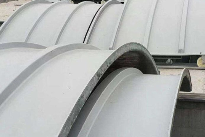
A tank cover looks like the least engineered part of a wastewater or chemical installation. It is a lid. It keeps rain out, keeps smell in, and occasionally carries a person. In practice it is the component that fails first, because it is the one surface where three different duties meet: it is the condensing surface for the acid that forms in the headspace, the structural element that has to carry a maintenance load over a span, and the sealing element that decides whether the odour-control system can hold negative pressure.
This guide works through those three duties in order - chemistry, loads and sealing - and then adds the two that are usually left out of the specification: gas collection and access. The numbers come from a calculation script so they can be checked. Product references point to the covers we build, such as the arched FRP cover hood for environmental protection equipment and the curved FRP cover plate for industrial sewage tanks.
1. What a Cover Does That a Tank Shell Does Not
A tank shell is designed around one dominant load case - internal hydrostatic pressure - and the design is dominated by hoop stress. A cover is designed around five loads simultaneously, none of which is hydrostatic, and the one that governs is usually not the one the buyer had in mind.
- Live load from access. A person walking on the cover, or a maintenance load placed on it. This is a concentrated load on a plate, not a pressure, and it produces local bending.
- Snow and wind. Snow is a uniform downward load; wind on an arch or a dome is an uplift load, and uplift acts in the direction that unseats the cover rather than pressing it down.
- Gas pressure and vacuum. A cover connected to an extract system runs at negative pressure; a blocked vent or a rapid fill can put it under positive pressure. Neither is a design pressure in the sense of a pressure vessel, but both are real.
- Thermal movement. A 6 m cover run moves 6 mm over a 40 K swing, and it moves differentially against the concrete or steel it is bolted to.
- Chemical attack from the inside. This is the load that never appears on a structural drawing and causes most of the premature failures.
There is no product standard that sets a live load for an FRP tank cover. That is not an oversight to be worked around; it is a fact that should be stated in the specification, because it means the load has to come from the project - from the owner's access policy and the local snow map - rather than from a supplier's catalogue. A cover sold as "walkable" without a stated load and a stated span is not a specification.
2. The Chemistry Under the Cover
The headspace above sewage or an organic effluent is a small chemical reactor. Sulfate-reducing bacteria in the submerged biofilm reduce sulfate to hydrogen sulfide, which escapes into the gas space. On the moist underside of the cover it is oxidised - biologically where biofilms establish, and chemically at high concentrations - to sulfuric acid. The concrete crown of a sewer and the underside of a tank cover fail by the same mechanism.
The numbers are well documented and they are not small. Hydrogen sulfide in sewer headspace typically runs from a few ppm to several hundred ppm, with measurements up to 550 ppm in extreme locations, and corrosion is considered to begin at concentrations as low as 2 ppm. At 25 to 50 ppm, cement paste loss in concrete headspaces has been reported at 1/16 to 1/8 inch per year - 1.6 to 3.2 mm per year. In a controlled test at 1,100 ppm, the surface pH of fresh concrete fell from 10.5 to 3.1 within 20 days, with a corrosion rate of 3.5 mm per year.
| Condition in the headspace | Measured or reported effect | Implication for the cover |
|---|---|---|
| Below about 2 ppm H2S | Odour threshold around 0.1 ppm; corrosion considered negligible | Standard isophthalic laminate with a surface veil is usually adequate |
| 25–50 ppm H2S | Cement paste loss of 1.6–3.2 mm per year in concrete | Vinyl ester corrosion barrier; no exposed fibre; sealed edges |
| Several hundred ppm H2S | Rapid acidification; pH at the surface falls into the 1–3 range | Full vinyl ester or dual-laminate construction; thicker barrier |
| 1,100 ppm H2S (test) | pH 10.5 to 3.1 in 20 days; 3.5 mm per year loss | Conventional corrosion barriers are consumed; design for replacement |
| Relative humidity 60–100 % | Condensation on the underside is continuous | The cover is always wet on the attack side; dry-side assumptions do not apply |
| Headspace CO2 around 1 % | Carbonation adds a second acid load | Do not rely on alkalinity for protection; it is not concrete |
It is worth converting the concentration into a mass flow, because that is what a maintenance engineer can picture. On a 12 m × 8 m covered tank with 1.5 m of freeboard, the headspace is 144 m³. At four air changes per hour the extract moves 576 m³/h. If that gas carries 50 ppm of hydrogen sulfide - 69.7 mg/m³ - the sulfide flow is 40.1 g/h, which on complete oxidation becomes 115.5 g/h of sulfuric acid. Over a year, if all of it condensed inside the cover, that is about one tonne of acid on a surface of roughly 96 m². The calculation is an upper bound, not a prediction, but it explains why a cover that "looks fine" at year one has a chalky, fibre-exposed underside at year five.
The cover is the coldest surface in the headspace and therefore the condensing surface. Every kilogram of sulfide that enters the gas space leaves as acid somewhere, and the somewhere is usually the underside of the lid.
3. Resin and Corrosion Barrier for Cover Laminates
Cover laminates are usually hand lay-up or vacuum-bag moulded, which means the corrosion barrier is applied by hand and its quality depends on the laminator rather than on a machine. That makes the specification of the barrier more important, not less.
The barrier has three jobs: keep the acid away from the load-bearing laminate, keep the laminate's fibre covered, and survive the condensation cycle without osmotic blistering. A practical build for sewage and municipal sludge service is a 0.4 to 0.5 mm surface veil layer - a C-glass or synthetic veil, never a chopped-strand mat exposed to the gas - followed by two layers of chopped-strand mat at roughly 0.6 mm each in a bisphenol-A epoxy vinyl ester, giving a barrier of about 1.5 to 2.5 mm before the structural laminate begins.
| Service | Resin | Barrier build | Notes |
|---|---|---|---|
| Municipal sewage, municipal sludge, grit channels | Bisphenol-A epoxy vinyl ester | Surface veil + 2 × 450 g/m² CSM, 1.5–2.5 mm | The default; tolerant of pH swings and of chloride |
| Industrial effluent with solvents or oxidisers | Vinyl ester, or dual-laminate with PP/PVDF | Veil + CSM, or thermoplastic liner | Check the solvent against the resin, not against "FRP" in general |
| Potable water, cooling water, clean stormwater | Isophthalic polyester | Veil + CSM, 1.5 mm | Cheaper; adequate where sulfide is absent |
| High-temperature gas, dry flue or hot process vapour | Vinyl ester with a high-heat distortion grade | Veil + CSM, plus a thermal barrier if required | Keep the surface below the resin's heat distortion temperature minus a margin |
| Food, pharmaceutical or potable-adjacent | Isophthalic or vinyl ester with an approved liner | Veil + CSM; no exposed fibre; sealed edges | Certification is project-specific; ask for the approval, not the claim |
Two details matter as much as the resin. The first is edge sealing: every cut edge of a cover panel is exposed fibre, and a cut edge in a sulfide environment wicks moisture along the fibres. Seal every edge with resin, and seal it again after any field cut. The second is the external face. A cover is exposed to UV and rain on top and to acid underneath, so the external surface needs a gelcoat or a UV-stabilised topcoat, and the underside needs the barrier - they are not interchangeable.
4. Loads and Load Combinations
Because no product standard sets the loads, the specification has to. The table below is the combination set we recommend discussing with the structural engineer; the values are typical project values rather than code-mandated figures.
| Load case | Typical value to specify | How it is applied | What it governs |
|---|---|---|---|
| Uniform live load, walk-on cover | 2.0 kN/m² | Over the whole panel | Panel thickness or rib depth |
| Concentrated live load | 1.0–1.5 kN on a 100 mm × 100 mm patch | At mid-span, worst position | Local bending and core crushing |
| Snow | From the local snow map, undrifted and drifted | Uniform, plus drift at parapets and adjacent structures | Long-span panels and arches |
| Wind uplift | From the local wind map, with the cover treated as a roof | Upward on the external face | Hold-down fixings rather than the panel |
| Extract vacuum | −50 to −250 Pa, stated by the odour system designer | Uniform upward on the underside | Fixings and gasket compression |
| Positive pressure | Relief device setting, or 1.5 × the maximum fill rate case | Uniform downward | Panel and seal, if the cover closes a tank |
| Thermal | Design temperature swing, typically 40–60 K | Restrained or free, as detailed | Fixings, joints and edge beams |
The vacuum case is the one most often omitted, and it is easy to demonstrate why it matters. A 2.0 m × 1.5 m panel has an area of 3.0 m². At 22 kg/m² it weighs 647 N. A vacuum of 50 Pa produces 150 N of uplift, which the self-weight comfortably resists; at 150 Pa the uplift is 450 N and the net is still downward at 197 N; at 250 Pa the uplift reaches 750 N and the panel is 103 N short - it lifts. The failure is not dramatic, it is a lid that breathes, leaks odour and frets its gasket. Specify the design vacuum, and specify hold-down clips for the design vacuum rather than for the self-weight.
5. When the Cover Is Also a Traffic Cover
Access covers set into a paved area are a different product from a tank cover, and they are covered by a different standard. EN 124-1 defines six load classes for gully tops and manhole covers, and EN 124-5 applies the same classification to composite covers. The proof loads are 15, 125, 250, 400, 600 and 900 kN for classes A15 to F900.
| Class | Proof load | Typical location | Comment for FRP covers |
|---|---|---|---|
| A15 | 15 kN | Pedestrian areas, footways, gardens | Within the capability of a moulded SMC cover |
| B125 | 125 kN | Car parks, sidewalks, residential driveways | Common composite class |
| C250 | 250 kN | Kerb channels and slow-traffic areas | Common composite class; check the frame as well as the cover |
| D400 | 400 kN | Carriageways, hard shoulders | Available in SMC; verify by test report, not by datasheet claim |
| E600 | 600 kN | Docks, loading areas, heavy vehicles | Limited availability in composite |
| F900 | 900 kN | Aircraft pavements | Normally cast iron or ductile iron |
Three requirements in EN 124 catch out suppliers who quote only the load class. The proof load has to be held for 30 seconds with no visible fracture. The permanent set after the load is removed must stay within the limit set by the standard for that class and size - the commonly quoted ratios are 1/100 of the clear opening for A15 and B125 and 1/300 for C250 to F900, with absolute caps for small openings, and some test houses quote 1/200 for openings up to 500 mm. The only safe course is to read the class-and-size table in EN 124-1 for the cover being bought, and to ask for the test report that shows the actual measured set. Composite covers are also tested for water absorption and fuel absorption, with limits of 0.3 % after 24 hours in water at 23 °C and 0.3 % after 168 hours in diesel, and for creep under two-thirds of the proof load held for 60 minutes.
For a tank cover that is not trafficked, EN 124 does not apply and should not be quoted. A Class B125 claim on a 3 m arched hood is a category error, and it is a useful way to check whether a supplier understands the product.
6. Geometry: Flat, Ribbed or Arched
The shape of the cover is a structural decision, and the arithmetic is unforgiving. A flat FRP plate in bending carries load through its thickness cubed, so deflection falls away very slowly as thickness is added, while an arch converts the same load into membrane compression and carries it through geometry instead.
For a 2.0 kN/m² live load, a flat panel spanning 2.4 m at 20 mm thickness deflects about 130 mm, which is L/19 - not a floor, and not even a lid. At 30 mm it is still 38 mm, or L/62. The linear plate formula becomes optimistic at those deflections, so treat the numbers as order-of-magnitude rather than design values; the conclusion does not change.
| Form | Span | Thickness / rise | Result at 2.0 kN/m² |
|---|---|---|---|
| Flat plate | 2.4 m | 20 mm | 130 mm deflection, L/19 |
| Flat plate | 2.4 m | 30 mm | 38 mm deflection, L/62 |
| Flat plate | 3.0 m | 30 mm | 94 mm deflection, L/32 |
| Arch, rise 0.15 L | 2.4 m | 12 mm, rise 360 mm | Thrust 4.0 kN/m, stress 0.33 MPa |
| Arch, rise 0.15 L | 3.0 m | 12 mm, rise 450 mm | Thrust 5.0 kN/m, stress 0.42 MPa |
| Arch, rise 0.15 L | 3.0 m | 16 mm, rise 450 mm | Thrust 5.0 kN/m, stress 0.31 MPa |
The arch numbers explain why nearly every large FRP tank cover is arched or domed. A 12 mm laminate at a rise of 0.15 times the span carries a 2.0 kN/m² load at 0.33 to 0.42 MPa, which is a small fraction of the laminate's strength. The load path, however, moves to the supports: 4 to 5 kN/m of horizontal thrust has to be taken by the edge beam or by a tie, and a cover detailed without a thrust path will push its own kerb outward. That is a design responsibility, not a manufacturing one, and it belongs in the drawing.
For smaller openings and rectangular panels, ribs are the alternative: a 100 mm deep rib at 600 mm centres turns a 6 mm skin into a stiffened plate. Ribs must be closed at the ends, because an open rib end is an exposed edge and a moisture path.
7. Sealing: Gaskets, Bolting and Galvanic Isolation
An odour-control cover is a seal, and the seal is usually the first thing to be value-engineered out. The gasket has to resist hydrogen sulfide and dilute sulfuric acid, hold compression set at ambient temperature, and survive being compressed and released every time the cover is opened.
EPDM at 70 Shore A is the default for this duty. Published data for a 70 Shore A EPDM gasket gives a service range of about −30 to +120 °C, a compression set of 20 % or less after 24 hours at 70 °C at 25 % compression, and excellent resistance to hydrogen sulfide, dilute and concentrated acids, and ozone - with oils and solvents listed as not recommended. That set of properties matches a sewage headspace almost exactly, and it is the reason EPDM rather than nitrile is the right default: nitrile is the better oil gasket and the poorer acid one.
| Material | H2S / dilute acid | Temperature | Where it fits |
|---|---|---|---|
| EPDM, 70 Shore A | Excellent | −30 to +120 °C | Default for sewage and sludge covers |
| Nitrile (NBR) | Not recommended for strong acid / H2S | −40 to +120 °C | Oil service only; wrong choice here |
| Neoprene (CR) | Fair | −40 to +120 °C | General weather seal, not the acid side |
| PTFE envelope | Excellent | Wide | Chemical duty with a compressible core; higher cost |
The bolted joint needs arithmetic as well as material. Fourteen M10 8.8 bolts at 25 N·m, with a nut factor of 0.20, give about 12.5 kN per bolt and 175 kN in total. Spread over a 20 mm wide gasket on a 5.0 m perimeter - 1,000 cm² of contact - that is 1.75 MPa of seating stress. EPDM static seals generally want 2 to 5 MPa to seat reliably, so this joint is marginal: the fix is not a wider gasket, which lowers the stress further, but more bolts, a narrower gasket, or a moulded O-ring in a groove that concentrates the same bolt load on a smaller area.
Two details complete the joint. Use slots rather than round holes where the cover has to move thermally - a 6 m run moves 6 mm over 40 K, and a round hole in a rigid cover will either elongate itself or crack the laminate. And isolate stainless fasteners from the FRP with a compliant washer and a bushing, not because the FRP corrodes but because a stainless bolt in a wet chloride environment will crevice-corrode at the thread root, and a bolt that cannot be undone is a cover that cannot be opened.
8. Gas Collection: Extraction Rate, Duct Sizing and Negative Pressure
If the cover is connected to an odour-control system, the extraction rate sets both the duct size and the sealing requirement. Air changes per hour is the usual design language. On the same 144 m³ headspace:
| Air changes | Extract flow | Duct at 8 m/s | Typical intent |
|---|---|---|---|
| 2 ACH | 288 m³/h (80 L/s) | DN113 | Light odour containment, closed vessel |
| 4 ACH | 576 m³/h (160 L/s) | DN160 | General coverage of a covered tank |
| 6 ACH | 864 m³/h (240 L/s) | DN195 | Open hatches, frequent access, higher emission |
| 8 ACH | 1,152 m³/h (320 L/s) | DN226 | High-strength sulfide, or a requirement to keep the headspace below a set concentration |
Two engineering points follow. First, the extraction rate has to be matched to the opening regime, not just to the tank volume: a cover with four hatches opened daily leaks far more than a sealed cover, and the extract rate is what keeps the headspace negative while they are open. Second, negative pressure is only useful if the cover is sealed. A cover that leaks at the gasket and at every panel joint cannot be held at −150 Pa; the fan simply moves more air, and the odour leaves through the nearest unsealed joint rather than through the duct.
Odour measurement, where a consent limit applies, is normally by dynamic olfactometry to EN 13725, reported in European odour units per cubic metre. That number belongs in the odour system design, not in the cover specification - but the cover is what decides whether the system can achieve it.
9. Access, Lifting and Confined Space
A cover is opened by people, and the access design determines whether it is opened safely or not at all.
- Panel weight. At 22 kg/m², a 1.5 m² hatch cover weighs 33 kg and needs two people; a 3 m² panel weighs 66 kg and needs a hinge, a davit or a lifting frame. Design the lifting point into the panel, not into the site.
- Hinges. A hinge transfers the whole panel weight plus the wind load into the kerb. Hinge plates should be laminated into the cover, not bolted through a 6 mm skin.
- Fall protection. A walk-on cover over a deep tank is a walking surface and a fall hazard at the same time. Where the cover is routinely accessed, the guardrail or the anchor point is part of the system.
- Confined space. Any tank that a person can enter is a permit-required confined space under 29 CFR 1910.146 unless the employer can demonstrate that the hazards are eliminated. Hydrogen sulfide is the reason the rule exists: the OSHA ceiling is 20 ppm with a single 50 ppm peak of up to 10 minutes per shift, the NIOSH recommended exposure limit is a 10 ppm ceiling over 10 minutes, the concentration considered immediately dangerous to life and health is 100 ppm, and the ACGIH threshold limit value is 1 ppm as an 8-hour average with a 5 ppm short-term limit. Odour is not a guide - olfactory fatigue sets in well before the dangerous range.
- Ventilation before entry. The extract system is not an entry-ventilation system. Test the atmosphere, then ventilate, then test again.
10. Inspection and Maintenance
Covers fail from the inside out, so the inspection has to be done from the inside, which means it happens during a shutdown and competes with everything else. A short, specific schedule is more likely to be followed than a generic one.
| Interval | Check | Acceptance |
|---|---|---|
| Quarterly, from outside | Gasket compression, bolt tightness, gelcoat chalking, ponding on the cover | No visible gap; no loose bolt; no ponding |
| Annually, from outside | Hold-down clips and hinge plates; sealant at penetrations | No movement under hand load; sealant continuous |
| Each shutdown, from inside | Barrier condition: gloss loss, fibre print-through, blistering, chalky surface | Barrier intact; no exposed fibre |
| Each shutdown, from inside | Joint and edge sealing; cut edges | Every edge sealed; no wicking |
| Each shutdown | Deflection under a known load, compared with the commissioning record | No progressive increase |
| 5-yearly | Barrier thickness by ultrasonic gauge or by coupon; Barcol hardness | Within the design allowance |
Repair follows the same logic as the inspection. Barrier damage that has not reached the structural laminate is repairable: abrade, dry, re-veil and re-resin with the original resin system. Damage that has exposed structural fibre, delamination, or a crack through a panel is replacement - a patch on a delaminated cover is a patch on a cover that has already lost its load path. And a cover whose barrier has been consumed across a large area is not worth local repair, because the next season will consume the repair as well.
Related reading on this site: FRP chemical storage tank safety covers containment, venting and bunding around the tank rather than the lid; tank nozzle and manway design sets out the bolt torque and gasket practice that the cover joint shares; FRP tank repair gives the laminate repair sequence; above-ground versus buried tanks explains the installation context; resin selection for chemical equipment goes deeper on the resin families used in the barrier; wet chlorine and chlor-alkali service covers the adjacent case where the gas phase is the aggressive medium; UV weathering and gelcoat deals with the external face; and tanks for liquid fertiliser and UAN shows the same cover-and-vent logic in a different chemistry. For the hardware, see the arched FRP hood, the curved cover plate, the flat sewage cover plate and the SMC access cover for trafficked openings.
Need help selecting FRP products?
Our engineers answer technical questions free of charge.
Ask an Engineer on WhatsApp