
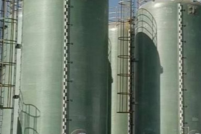
Sodium hypochlorite is not the most aggressive chemical an FRP tank will ever see. Twelve and a half per cent bleach is mild next to thirty-seven per cent hydrochloric acid or hot sodium hydroxide, and there are plenty of tanks in service that have held it for twenty years. What makes hypochlorite unforgiving is that it fails slowly and invisibly. The oxidiser attacks the resin matrix rather than the glass, the attack proceeds through a liner that can still look sound from the outside, and the first symptom is often a weep at a knuckle or a discoloured patch near the bottom, by which time the barrier has already lost a substantial part of its design life. This guide covers the resin decision that determines the outcome, why the corrosion barrier rather than the structural laminate is the real tank, a worked 30 cubic metre tank with its design pressure and layer thicknesses, and the venting calculation that shows how little of the vent duty is actually caused by off-gassing — and why the vent still cannot be blocked.
1. What Makes Hypochlorite Different
Three properties drive every storage decision.
- It is a strong oxidiser, and the attack is on the resin. Hypochlorite attacks the ester linkages in the polymer backbone. Orthophthalic and isophthalic polyester resins are broken down quickly; the resin does not soften, it degrades, and the degradation runs inward through the liner while the outside of the shell stays intact.
- It decomposes, and the decomposition products matter. The main path is 2 NaOCl to 2 NaCl plus O2. A second path produces chlorate. The reaction releases oxygen, which means the tank is never truly static, and it also means the product strength falls over time in storage whether or not anything is wrong with the tank.
- Trace metals accelerate the decomposition. Dissolved iron, copper, nickel or manganese ions catalyse the breakdown of hypochlorite. This is why metal fittings in the wetted area are a design error rather than a maintenance nuisance: they do not merely corrode, they spoil the contents.
Temperature and light both accelerate the same chemistry. The widely quoted storage guidance is to keep hypochlorite below about 27 degrees Celsius, out of direct sunlight, and to avoid an oversized tank that holds the product for longer than necessary — every extra month of residence time is extra decomposition, and an oversized tank is a slower and more expensive way to deliver weaker chemical.
2. The Resin Decision
Resin choice is the single decision that separates a tank that lasts twenty years from one that fails in three. Two resin families are viable and the rest are not.
| Resin | Suitability for hypochlorite | Notes |
|---|---|---|
| Bisphenol-A epoxy vinyl ester | Preferred | The standard workhorse for oxidiser service; the bisphenol-A backbone resists hydrolysis and the methacrylate end groups cure to a dense, low-permeability network |
| Novolac (epoxy novolac) vinyl ester | Preferred where hot or concentrated | Higher cross-link density and a higher Heat Distortion Temperature; the choice when the service runs warm |
| Isophthalic polyester | Not recommended | Degrades materially faster under sustained oxidiser exposure; acceptable only for very dilute, ambient, short-residence duty and never as the barrier in a bulk tank |
| Orthophthalic polyester | Excluded | Ester linkages are attacked directly; not a barrier material for bleach |
| Epoxy (amine or anhydride cured) | Not the first choice | Strong on caustics and solvents, but vinyl ester is the better oxidiser resin and cures faster at ambient, which suits large field lay-ups |
The catalyst system belongs in the same conversation. A cobalt-catalysed cure leaves cobalt in the laminate, and cobalt is one of the ions that catalyses hypochlorite decomposition at the wetted surface. A cobalt-free system is the standard requirement for hypochlorite tanks, and it is a factory decision: it is not something that can be corrected on site after the tank arrives. Ask for it in writing on the resin datasheet rather than assuming it.
Where a customer wants additional margin, for example where inspection access is difficult or the contents are high value, a thermoplastic liner bonded to the FRP structure is the next step up. Fluoropolymer and other dual-laminate constructions put a continuous non-permeable sheet between the chemical and the resin, at the cost of a more demanding fabrication process and a bond whose quality is critical at every nozzle and every cut edge.
3. The Corrosion Barrier Is the Tank
The structural laminate behind the liner has a chemical resistance of a different order. It is built for strength, with a relatively low resin content and a high glass fraction, and it is deliberately not optimised as a barrier. The corrosion barrier is the part that touches the chemical, and it is the only part that is designed for the service.
A conventional construction is a resin-rich barrier built up from two layers of chopped strand mat and two layers of synthetic veil, giving a nominal thickness of 100 mil, or 2.5 mm. A 200 mil barrier, built from four mat layers and two veils, roughly doubles the time before the chemical reaches the structural laminate. The veil layer carries no structural load at all; its job is to produce a resin-rich, fibre-lean surface that resists the initial attack and keeps the mat layers behind it from being exposed.
The chemical never sees the structural laminate. It sees the liner, and the liner is what you are buying. A quotation that names the resin but not the barrier construction has left the most important line off the page.
Three details decide whether that construction survives.
- Every cut edge is a potential breach. Nozzle cut-outs, manway openings, drain penetrations and secondary bonds all expose glass if they are not sealed. Each exposed edge has to be resealed with the same resin-rich, veil-reinforced build-up as the shell, and the sealing has to be inspected rather than assumed.
- The cure of the barrier is separate from the cure of the shell. A barrier that is under-cured stays permeable and loses the resistance you paid for. Barcol hardness readings taken on the barrier surface, not just the shell, are the evidence that the cure happened.
- Barrier thickness has to be measured, not counted. A specified number of mat and veil layers produces a nominal thickness, and the nominal numbers are what get quoted. Measuring the finished barrier at several points around the shell and at each nozzle is the only way to know what was built.
4. Worked Example: A 30 Cubic Metre Vertical Tank
Take a vertical cylindrical tank with a dished bottom, holding 30 cubic metres of 12.5 per cent sodium hypochlorite at a specific gravity of 1.20. The geometry and the design pressure come first, because everything else follows from the hydrostatic head.
| Quantity | Value |
|---|---|
| Diameter | 2.600 m |
| Straight shell height | 5.600 m |
| Dished bottom contribution to liquid depth | 0.650 m |
| Cylindrical volume | 29.73 m3 |
| Volume of the dished bottom | 2.30 m3 |
| Total geometric volume | 32.03 m3 |
| Freeboard over a 30 m3 working volume | 2.03 m3, or 6.3 per cent |
| Liquid depth at full working volume | 6.25 m |
With a density of 1200 kg per cubic metre, the hydrostatic pressure at the bottom is 1200 x 9.81 x 6.25, which is 73,575 Pa, or 0.736 bar. For an atmospheric tank a vent allowance is added — the conventional minimum is 0.25 psi, about 1,724 Pa — giving a design pressure of 75,299 Pa, or 0.753 bar. That is a small number in absolute terms and it is the reason a hypochlorite tank is a thin-wall structure governed by stiffness, wind, seismic and nozzle loads rather than by internal pressure alone.
Taking a design allowable of 10 MPa in tension for the structural laminate, the pressure requirement alone gives a wall of 9.79 mm. Adding a 4.0 mm barrier produces a nominal shell of about 13.8 mm.
| Shell course | Depth to the bottom | Pressure | Hoop stress at 13.8 mm | Wall needed |
|---|---|---|---|---|
| 1 (lowest) | 6.25 m | 75.3 kPa | 7.10 MPa | 9.79 mm |
| 2 | 5.00 m | 60.6 kPa | 5.71 MPa | 7.88 mm |
| 3 | 3.75 m | 45.9 kPa | 4.32 MPa | 5.96 mm |
| 4 | 2.50 m | 31.2 kPa | 2.94 MPa | 4.05 mm |
| 5 (top) | 1.25 m | 16.4 kPa | 1.55 MPa | 2.14 mm |
A single full-height shell of 13.8 mm is governed entirely by the bottom course, which means the upper courses carry about 78 per cent more laminate than they need. That is not necessarily wrong — a uniform wall simplifies fabrication and keeps the barrier construction identical everywhere — but it should be a decision rather than a default, because the alternative is a stepped or tapered shell that saves material at the top while keeping the barrier detail the same.
The barrier thickness itself is worth looking at as a fraction of the wall, because that fraction is what determines the service life and it moves with every change of specification.
| Barrier thickness | As a fraction of a 13.8 mm wall | Structural laminate behind it |
|---|---|---|
| 100 mil (2.5 mm) | 18.4 per cent | 11.2 mm |
| 160 mil (4.1 mm) | 29.5 per cent | 9.7 mm |
| 200 mil (5.1 mm) | 36.8 per cent | 8.7 mm |
5. Venting: What Off-Gassing Actually Demands
Hypochlorite decomposes, decomposition releases oxygen, and the instinct is that the vent must therefore be sized for the gas. The calculation says otherwise, and it is worth doing because it changes where the vent protection effort belongs.
The tank holds 30 cubic metres at a density of 1200 kg per cubic metre, which is 36,000 kg of solution. At 12.5 per cent available chlorine that is 4,500 kg of available chlorine. Treating the decomposition as 2 NaOCl to 2 NaCl plus O2, one mole of oxygen is released per mole of chlorine equivalent lost.
| Loss rate, per cent of available chlorine per month | Chlorine equivalent lost | Oxygen released | Oxygen volume per month | Continuous rate |
|---|---|---|---|---|
| 0.25 per cent | 11.2 kg | 159 mol | 3.56 m3 | 0.00137 L/s |
| 0.50 per cent | 22.5 kg | 317 mol | 7.11 m3 | 0.00274 L/s |
| 1.00 per cent | 45.0 kg | 635 mol | 14.23 m3 | 0.00549 L/s |
| 2.00 per cent | 90.0 kg | 1,269 mol | 28.45 m3 | 0.01098 L/s |
| 5.00 per cent | 225.0 kg | 3,173 mol | 71.13 m3 | 0.02744 L/s |
Even at an aggressive five per cent per month, which no well-managed tank approaches, the off-gas rate is 0.027 litres per second. Compare that with the air the vent has to pass when the tank is filled or drawn down. At a 20 cubic metre per hour delivery rate, the displaced air flow is 5.556 litres per second. Off-gas is 0.099 per cent of that at the one per cent per month case. Thermal breathing is smaller again: a 2.03 cubic metre headspace expanding through a 15 kelvin daily swing displaces about 0.10 cubic metres per day, which is 0.00118 litres per second.
Fill displacement governs by a factor of about two hundred over off-gassing, and by a factor of about five thousand over breathing. The vent sizing therefore follows the fill rate, not the chemistry.
| Sizing basis | Result |
|---|---|
| Free-vent velocity 3 m/s at 5.556 L/s | 1,852 mm2, bore 48.6 mm |
| Free-vent velocity 5 m/s at 5.556 L/s | 1,111 mm2, bore 37.6 mm |
| Free-vent velocity 8 m/s at 5.556 L/s | 694 mm2, bore 29.7 mm |
| Piping rule: at least 1.5 to 2 times the largest fill or discharge connection | A DN80 delivery line therefore requires a DN150 vent |
| Velocity through a DN150 vent at 5.556 L/s | 0.31 m/s |
The calculation says DN50 would be adequate on velocity grounds. The piping rule says DN150, and the piping rule governs by a large margin, for a good reason: the vent has to pass the worst transient, not the average one, and a vent that is marginal in normal service will be blocked by a deposit or a bird's nest long before it is undersized on paper. The correct conclusion from the off-gassing number is not that the vent can be small. It is that the vent cannot be blocked, because an atmospheric tank with a blocked vent becomes a pressure vessel, and a hypochlorite tank is not built as one.
Three vent requirements follow:
- The vent must be permanently open and sized for the maximum fill and withdrawal rate, with a secondary relief path in case the primary blocks.
- The vent line, overflow and drain must be in a material compatible with hypochlorite — FRP or a suitable thermoplastic — not carbon steel or standard stainless steel.
- Indoor installations should pipe the vent outdoors. The oxygen is not toxic, but the headspace atmosphere carries trace chlorine and the tank is not a sealed system.
6. Temperature, Light and the Ageing of the Product
The resin is only half the story. Hypochlorite loses strength in storage, and the tank design influences how fast. Two factors dominate: temperature and residence time.
| Months stored | Available chlorine at 25 C, 1.0 per cent per month | Available chlorine at 35 C, 2.1 per cent per month |
|---|---|---|
| 1 | 12.38 per cent | 12.24 per cent |
| 3 | 12.13 per cent | 11.73 per cent |
| 6 | 11.77 per cent | 11.01 per cent |
| 12 | 11.08 per cent | 9.69 per cent |
At 25 degrees a tank still meets a nominal 12.5 per cent specification after a year. At 35 degrees it does not reach twelve months, and a specification written around the label strength will be missed by a wide margin in the second half of the year. The practical measures are the ones already in the storage guidance: shade the tank or insulate it, keep it out of the afternoon sun, and keep the tank small enough that the product turns over.
Ultraviolet light attacks hypochlorite directly and also degrades the resin. The tank exterior therefore needs an opaque, pigmented, UV-inhibited finish, not a translucent or natural gel coat. This is a specification item, not a preference: an outdoor tank without an opaque exterior is being degraded from both sides at once.
7. Metals, Nozzles and Wetted Parts
The rule is simple and it is routinely broken. No metal that touches the stored hypochlorite, and no metal that can drip into it.
- Nozzles: FRP nozzles built with the full corrosion barrier, or a compatible thermoplastic. Titanium is the one metal generally acceptable in hypochlorite service and is sometimes used for sidewall connections, but FRP is the simpler answer.
- Gaskets: confirmed compatible with hypochlorite by the gasket supplier, not by assumption.
- Bolting and supports: external to the wetted area, and protected from drips and spillage. Keep the support structure clear of any path that could carry a leak back onto the shell.
- Instrumentation: level transmitters, gauges and sample valves on non-metallic wetted parts.
- Pipework: supported independently of the tank, so that pipe loads and differential movement do not put a bending moment into the shell or a nozzle.
8. Secondary Containment and Layout
Containment capacity is usually specified as at least 110 per cent of the volume of the largest tank in the bund. For the example tank the geometric volume is 32.03 cubic metres, so the containment must hold at least 35.24 cubic metres, or about 35,200 litres. Two details are commonly missed: the containment material must itself be resistant to hypochlorite, which rules out an untreated concrete sump, and the bund must be large enough to hold the tank volume plus whatever rainwater or firewater it collects.
9. What to Put in the Enquiry
A complete enquiry for a hypochlorite tank is short, and the four items in it are the ones that determine the tank:
- Chemistry: hypochlorite concentration as available chlorine, pH, and any other components. If the conditions are acidic enough to favour hypochlorous acid over the hypochlorite ion, say so — the equilibrium and hence the aggressiveness change with pH, and storage at a stabilised alkaline pH is a different duty from an acidic splash.
- Conditions: minimum and maximum liquid temperature, indoor or outdoor, expected sun exposure, and expected residence time.
- Geometry and flow: working volume, diameter and height constraints, and the maximum fill and withdrawal rate, from which the vent sizing follows.
- Documentation: the fabrication standard, the resin and cure system, the barrier construction and measured thickness, Barcol hardness records, and a water fill test.
Inspection access belongs on that list too. Because the failure mode is a slow loss of the barrier, the ability to get inside the tank and inspect the liner, particularly the knuckle where the shell meets the bottom and the areas around each nozzle, is what decides whether a developing problem is caught while it is still a relining job. A tank with no manway is a tank with no maintenance history.
10. FAQ
Can a tank that held water be used for hypochlorite? Only if it was built with a vinyl ester barrier and a cobalt-free cure. A general purpose polyester tank that has held water is not suitable, and the fact that it has no history of attack does not mean it is compatible.
Is a thicker barrier always better? It buys time before the chemical reaches the structural laminate, which is what the barrier is for, so within reason yes. The cost is fabrication quality: a thicker hand-laid barrier is harder to cure and harder to keep free of voids, and a 5 mm barrier with voids in it is worse than a 2.5 mm barrier without any.
Why does the resin supplier's hypochlorite temperature limit sit below its general service limit? Because the oxidiser is a specific case. A resin rated to 100 degrees for general chemical service is often rated much lower for hypochlorite, and the hypochlorite-specific figure is the one that applies. Ask for it explicitly.
How often should the liner be inspected? The interval should be set by the severity of the duty and the consequence of failure, and then shortened whenever an excursion in temperature or pH has occurred. Contamination of a hypochlorite tank by a metal ion or an acid excursion can do several years' worth of damage in one event.
What is the realistic service life? A premium vinyl ester barrier is commonly quoted at fifteen to twenty years before relining, and relining replaces the barrier and leaves the shell to run a further twenty years or more. The tanks that reach those numbers are the ones where the barrier construction and the cure were specified and verified, not the ones where a generic datasheet was accepted.
11. Specifying a Hypochlorite Tank
At Henan HuanGang we build filament-wound FRP and GRP storage tanks for acid, alkali and oxidiser service with bisphenol-A and novolac vinyl ester systems, and the first thing we ask about a bleach enquiry is the cure system rather than the volume. Send us the concentration as available chlorine, the temperature range, the residence time and the fill rate, and we will come back with the resin, the barrier construction, the shell thickness by course and the vent size, with the reason for each one. If the tank is replacing a unit that failed early, tell us how it failed — the failure mode usually identifies which of the decisions above was made wrongly.
Related reading: resin selection: vinyl ester versus isophthalic and orthophthalic, gel coat and corrosion barrier liner design for FRP tanks, dual laminate FRP with thermoplastic liners, FRP chemical tank safety, vertical FRP storage tanks, tank nozzle and manway design, field erection, joint lamination and post-cure, FRP tank repair, FRP vessels to ASME Section X and RTP-1, acoustic emission testing of FRP tanks and FRP versus stainless steel.
Need help selecting FRP products?
Our engineers answer technical questions free of charge.
Ask an Engineer on WhatsApp