
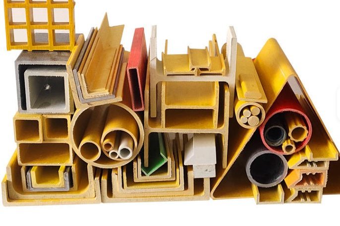
Bolting is how most pultruded FRP frames get assembled, but bonding is the connection that actually suits the material. An adhesive spreads load across the entire overlap; a bolt concentrates it into a few crushed hole walls. Bonded joints are also stiffer, fatigue better, and leave no drilled hole for moisture to enter. The catch is that the two variables that decide whether a bond holds — surface energy and joint geometry — are both invisible once the assembly is closed. This guide covers what to specify, what to measure, and what to test, with the numbers that procurement arguments usually turn on.
One structural point needs stating up front, because it changes how a bonded design is documented. ASCE/SEI 74-23, the LRFD standard for pultruded FRP structures, addresses members and bolted connections (Chapter 8). It does not provide bonded-joint provisions. Europe's CEN/TS 19101:2022 does cover bolted, bonded and hybrid joints and is the more complete reference for adhesively bonded design. A bonded connection therefore has to be justified either against a code that covers bonding or against project-specific test data — and that decision belongs in the specification, not in the fabrication shop.
1. What Bonding Buys, and What It Costs
The case for bonding is mechanical rather than cosmetic. In a bolted FRP joint the load path passes through holes whose fibers have been cut, and the allowable bearing stress is a fraction of the laminate's tensile strength. Bonding keeps the fibers continuous and transfers load in shear over a large area, which is why joint efficiency is higher and the joint is far stiffer. The 2024 CEN review of CEN/TS 19101 makes the same point from the design side: adhesive connections and joints required dedicated provisions precisely because their behaviour is not captured by rules written for bolted connections.
The costs are real and should be quoted alongside the benefits:
- Not demountable. A bonded frame cannot be taken apart for transport or later modification. Bolted-then-bonded or bolted-only details exist for exactly this reason.
- Inspection is indirect. There is no equivalent of looking at a bolt. Quality has to be built in through preparation records and witnessed by coupon tests.
- Shop conditions matter. Temperature, humidity and dew point govern the result, and a site-bonded joint is worse than a shop-bonded one for that reason alone.
- Temperature ceiling. Every adhesive loses stiffness as it approaches its glass transition temperature. A bonded joint has a service-temperature limit that a bolted joint does not.
If the joint cannot be prepared, clamped and cured under control, do not bond it. A poorly bonded joint fails without warning; a bolted joint gives you a loosened bolt first.
2. Where Bonded FRP Joints Actually Break
Designing a bonded joint starts by knowing which failure mode will govern. In the laboratory testing of epoxy-bonded single-lap and double-lap joints made from pultruded GFRP flat sections (Keller and Vallée, Composites Part B 36, joints with overlaps from 50 to 200 mm, adhesive layers from 1 to 3 mm and adherends from 3 to 12 mm thick), failure was initiated by a combination of through-thickness tension (peeling) and shear at the two overlap ends — in the adhesive fillet and in the outer fiber-mat layers of the adherends. Propagation then always occurred in the outer fiber-mat layers. No cohesive or interface failure of the adhesive itself was observed. In other words, the adhesive out-performed the composite, and the composite lost.
| Failure mode | Where it starts | Driving stress | Practical control |
|---|---|---|---|
| Fiber tear / delamination in the adherend | Outer fiber-mat layers, ~0.5 mm below the bonded surface | Combined through-thickness tension and shear at overlap ends | Longer overlap, double lap, taper, spew fillet; do not rely on peel strength |
| Interface (adhesive) failure | At the bond line itself | Shear, but triggered by weak adhesion | Surface preparation discipline; water break test on every prepared area |
| Cohesive failure in the adhesive | Mid-bondline | Shear exceeding adhesive strength | Adhesive selection, adequate overlap, correct bondline thickness |
| Peel / cleavage at the joint edge | First 5–10 mm of the overlap | Eccentricity-induced bending | Symmetric double lap, adherend tapering, continuous fillet |
| Creep rupture under sustained load | Whole bondline | Long-duration shear at temperature | Cap sustained stress well below short-term strength; time-effect factor on design |
Two conclusions follow. First, a stronger adhesive does not produce a stronger joint if the failure path runs through the composite. Second, because the critical material is the surface veil and the mat layers of the pultruded profile, the profile's own surface quality — the part most suppliers never discuss — is a design variable.
3. Surface Preparation: The Part That Decides the Result
A bond is only as good as the chemistry at the interface, and the interface is the one thing you cannot inspect afterwards. The sequence below is not a suggestion; changing the order changes the outcome.
- Degrease first, with clean solvent and clean wipes. Acetone, methyl ethyl ketone (MEK), isopropyl alcohol or methyl alcohol are suitable. Do not soak pultruded profiles in solvent — wipe and allow to evaporate. This step removes mold release, handling oils and the film that forms in storage.
- Abrade to remove the surfacing veil. Roughly 80–120 grit is enough to cut through the veil without gouging fibers. The guide given in pultruder fabrication literature is that sanding is sufficient once the surfacing veil has been removed; power sanding is normal on large areas.
- Remove dust with a dry, clean brush or cloth. Do not wipe the freshly abraded surface with a solvent-dampened rag — that re-deposits dissolved contamination into the open surface. If the surface is touched or becomes contaminated, repeat the sequence including a light re-sanding.
- Bond within the working window. Freshly prepared surfaces are reactive; assemble as soon as the adhesive is mixed, ideally within 20–30 minutes. Keep prepared parts covered if there is any delay.
- Check it, do not assume it. A water break test — a film of clean water applied to the prepared area — should spread and hold as a continuous sheet rather than pulling back into beads. Beading is direct evidence of low surface energy and residual contamination. If the adhesive beads up during application, the same thing is happening, and the joint is already scrap.
Peel-ply surfaces are an alternative to abrasion where profiles are supplied with a peel ply: the ply is removed immediately before bonding, which presents a fresh, uncontaminated surface with no sanding. Where peel ply is used, still confirm the finish with a water break test — peel plies vary, and some leave residues.
| Surface condition | Correct preparation | Water break result | If it is skipped |
|---|---|---|---|
| As-delivered pultrusion | Solvent wipe → abrade to bare veil-free laminate → dry dust removal | Continuous film, no beading | Interface failure at very low load |
| Previously bonded, old adhesive | Grind back to laminate; never bond onto cured adhesive | Continuous film | Disbond along the old glue line |
| Machined or drilled edge | Remove loose fiber dust, seal with resin, then prepare | Continuous film | Resin-starved, dusty interface |
| Wet or damp surface | Dry thoroughly; measure dew point before bonding | Film does not form on damp laminate | Voids and long-term interfacial failure |
4. Choosing the Adhesive Chemistry
Three chemistries dominate structural bonding of FRP: two-part epoxy, methyl methacrylate (MMA, also called structural acrylic), and two-part polyurethane. Datasheet-level bulk properties differ substantially, and so does the discipline each one demands.
| Property | Two-part epoxy | MMA / structural acrylic | Two-part polyurethane |
|---|---|---|---|
| Typical bulk lap shear strength | Highest, roughly 25–40 MPa | High, roughly 20–30 MPa | Lower, roughly 15–25 MPa |
| Elongation / stiffness | Low, typically 2–10%; rigid | Medium to high depending on grade | High, often 100%+ |
| Peel and impact resistance | Moderate; can be brittle | Excellent; rubber-toughened grades | Excellent |
| Surface preparation demand | High — abrasion plus degreasing is essential | Lower; more tolerant of imperfect surfaces | Moderate |
| Fixture speed | Handling after roughly 8 hours; full cure 24–48 hours | Handling in minutes; most strength within hours | Hours |
| Gap filling | Moderate | Excellent; some grades fill very large gaps | Good |
| Service temperature | Highest of the three | Broad but lower than epoxy at the top end | Lowest |
| Best fit | High-temperature and chemical service; shop assembly | Fast shop assembly, mixed-material joints, impact loads | Flexible joints, moisture-tolerant service |
Two cautions. First, those shear figures are bulk adhesive properties measured on a rigid substrate; they are not the strength of your joint, because your joint will probably fail in the laminate at a lower stress. Second, "MMA needs less preparation" is not a licence to skip preparation. It is a tolerance for imperfect preparation, and the difference between excellent and marginal preparation is the difference between a joint that lasts the design life and one that disbonds at the edge in year three.
5. Bondline Thickness, Fillets and Clamping Pressure
The standard test method for FRP lap shear (ASTM D5868) fixes the bondline at 0.76 mm using glass beads in the adhesive, with a 25.4 × 25.4 mm overlap and a 13 mm/min loading rate, and requires at least five specimens. That 0.76 mm is a test-control dimension, not a design requirement, but it is a good working target. In practice, bondlines between roughly 0.5 and 1.0 mm behave predictably; below 0.2 mm the adhesive starves and voids form, above about 2 mm the glue line becomes a compliant layer that sheds stiffness.
The interesting experimental finding is what doesn't matter much. In the Keller and Vallée double-lap programme, adhesive layer thickness in the range 1–3 mm had insignificant influence on ultimate failure load and on the stress distribution along the overlap. What mattered far more was the fillet radius. The practical translation: spend your effort on the squeeze-out detail, not on chasing a tenth of a millimetre of glue line.
| Detailing item | Target | What goes wrong if it is missed |
|---|---|---|
| Bondline thickness | 0.5–1.0 mm (test reference 0.76 mm) | Too thin: voids and starvation. Too thick: compliant joint, low stiffness |
| Spew fillet | Continuous bead at both overlap edges, radius roughly 3–6 mm, left in place | Sharp edge becomes the peel crack initiator; filleting is the single most effective geometric fix |
| Clamping | Even pressure, held for the full cure; 20–24 hours where ambient cure is used | Parts drift, bondline thickness varies, joint creeps open before cure |
| Assembly environment | Substrate temperature at least 3 °C above dew point | Condensation on the prepared surface; adhesion failure with no visible cause |
| Full load application | Not before full cure (typ. 48 hours at 21 °C for ambient-cure epoxy) | Early loading on a green bondline; permanent creep deformation |
Where adhesive cannot be applied cleanly — overhead positions, vertical faces, wide and irregular gaps — choose a non-sag grade rather than thickening a sagging one with filler. Filler changes the modulus, the shrinkage and the creep behaviour, and none of that will match the datasheet you designed to.
6. Overlap Length: Why More Stops Helping
The load in a lap joint is not uniform. Shear stress peaks at the two ends of the overlap and falls away in the middle, because the adherends stretch and shed load as the adhesive strains. Shorten the overlap and the peaks climb; lengthen it and the peaks flatten until the middle of the joint is doing very little work. This is why the measured ultimate failure load in the pultruded GFRP lap joint programme converged to a constant value as overlap length increased. Past that point, extra length adds material, adhesive and cost without adding capacity.
A simple sizing check gets you into the right range before you run any analysis. Take the design load, divide by the bond width to get a force per unit length, and divide by a conservative interface shear capacity to get the required overlap:
Required overlap = design load ÷ (bond width × allowable shear stress)
Worked example: a 100 mm wide leg of pultruded angle carries a sustained 20 kN. At an allowable interface shear stress of 4 MPa (a conservative value that keeps the failure path out of the laminate): 20,000 N ÷ (100 mm × 4 N/mm²) = 50 mm. Specify 75–100 mm to absorb eccentricity, site tolerances and any local loss of bond at the edges.
Two adjustments sit on top of that number. Under sustained load, cap the sustained shear stress well below the short-term value — creep rupture, not static strength, governs a permanent joint. And where the joint is loaded in tension rather than shear, stop and redesign the geometry: a lap pulled apart in peel is a different and much weaker animal.
7. Joint Geometry That Kills Peel
Peel is the enemy and it is a geometry problem, not a material problem. The single-lap joint is the simplest and the weakest, because the load paths are offset and the resulting bending moment drives a peel stress peak at one end. Everything below is an attempt to remove that eccentricity or to blunt its effect.
| Geometry | Peel demand | Relative efficiency | Where it fits |
|---|---|---|---|
| Single lap | High | Lowest of the family | Light frames, secondary members, low load |
| Double lap / double strap | Moderate — eccentricity is reduced but not removed | Good | Structural splices; two bonded faces, symmetric |
| Tapered adherend end | Reduced | Good | Moment connections, member ends |
| Reverse taper with fillet | Lowest in the taper family | Best of the tapered options | Where the joint must be flush on the outer face |
| Scarf | Effectively eliminated in a well-made joint | Highest | Thick sections; bonded repairs where thickness must be preserved |
| Stepped lap | Moderate, controlled by step geometry | Good | Built-up laminates |
Two warnings that feel counter-intuitive. First, tapering is not automatically beneficial: finite element studies of tapered laminate ends without an adhesive fillet found peaking of the peel stress component, and the direction of the effect depended on the relative stiffness of laminate and adhesive. The reliable combination is tapering plus a fillet. Second, in stepped laminates the step length has to be long enough to redistribute load — for a stiff adhesive, at least ten times the added thickness at each step. Short steps create a new stress concentration at every step boundary.
8. Design Values, Partial Factors, and What the Codes Actually Cover
Bonded joints sit in an awkward gap in the standards landscape. The table below summarises what can be cited and for what.
| Reference | Scope | Bonded joints | Temperature limit | Design basis |
|---|---|---|---|---|
| ASCE/SEI 74-23 | Pultruded FRP structural shapes and prefabricated products | Not covered — Chapter 8 is bolted connections | Service temperature limited to Tg − 22 °C | LRFD: Ru ≤ λφRn, with time-effect factor λ |
| CEN/TS 19101:2022 | Fibre-polymer composite structures, buildings and civil works | Covered, together with hybrid bolted-bonded joints | Between −40 °C and Tg − 20 °C | Eurocode partial factor format per EN 1990, with durability provisions for joints |
| ASTM D5868 | Test method: lap shear adhesion for FRP bonding | Defines the test, not the design | Test at specified temperature | Comparative apparent shear strength; failure mode per ASTM D5573 |
| ASTM D2093 | Practice for preparing plastic surfaces before bonding | Preparation guidance | — | Process control |
| Project test programme | Your materials, your surface preparation, your cure | The evidence for your numbers | Worst-case service temperature | Statistically based design value from a qualification batch |
For the partial factor on a bonded joint, published research on pultruded GFRP lap joints derived a partial material safety factor for joint strength of 1.34 from measured and predicted strengths. Treat that as a reference point for what a defensible factor looks like, not as a number to copy: the factor has to reflect the scatter of your own production preparation and cure.
The practical outcome is a two-line specification: state the code or test basis for the design value, and state the acceptance test that will be run on production material using production preparation. Without the second line, no one can tell whether the joint in the field is the joint that was designed.
9. Durability: Temperature, Moisture, Creep and Movement
Bonded joints in industrial plants are asked to hold load for twenty years while the weather and the process do their worst. Four mechanisms decide whether they do.
- Temperature. Both codes above express the ceiling relative to the glass transition temperature of the material — Tg − 22 °C for pultruded profiles under ASCE/SEI 74-23, and Tg − 20 °C for composites under CEN/TS 19101. Adhesives have their own Tg, usually lower than the profile's. The correct limit is the lower of the two, taking the moisture-conditioned value rather than the dry value.
- Moisture. Water reaches the bondline through the exposed edges and through the adherend. ASCE/SEI 74-23 requires material that retains at least 75% of its strength after damp-heat, UV and freeze-thaw exposure; a bonded joint specification should demand the equivalent evidence for the adhesive system, tested wet rather than dry.
- Creep. Adhesives creep under sustained shear, and the rate rises steeply with temperature. This is why the time-effect factor exists and why a permanent bonded joint should never be sized off short-term lap shear data.
- Differential movement. Pultruded GFRP has an axial coefficient of thermal expansion of roughly 6–12 × 10−6/°C and a transverse value of roughly 20–30 × 10−6/°C, while epoxy adhesives sit at roughly 50–100 × 10−6/°C. Across a 1 mm bondline the mismatch is trivial; over the length of a member it is not. A 6 m FRP member bonded to a concrete or steel substrate through a 40 °C swing moves about 6,000 mm × 8 × 10−6 × 40 °C ≈ 1.9 mm, and that movement has to be taken up in shear by the adhesive or released by a slip detail.
10. Redundant Load Paths: Designing the Joint You Cannot Inspect
Because a bonded joint gives no external warning before it fails, good practice is that the bond should never be the only thing holding the structure up. The requirement appears in pultruder design guidance in exactly those words: all bonded connections must be designed with a redundant load path, because adhesives can fail suddenly at their glass transition temperature.
Practical ways to build that redundancy into a pultruded frame:
- Hybrid joints. Bond the faces and bolt through the same overlap. Detail the bolts in slotted or oversized holes so they do not carry load until the adhesive has slipped, then design the bolts to hold a defined fraction of the working load. CEN/TS 19101 treats hybrid joints as a category in their own right for this reason.
- Mechanical interlock. A lip, cleat, shoulder or bracket that takes the load in bearing if the bond fails converts a single-path connection into a two-path one at negligible cost.
- Secondary bonding over the joint. Where aesthetics allow, laminate a layer of mat and resin over a bonded joint. This is standard practice in boatbuilding and it converts a peel-sensitive bondline into a laminated lap. Do not confuse it with structural adhesive bonding — different chemistry, different rules.
- Declared failure mode. State in the specification which mode is acceptable and what the post-bond reserve capacity must be. "Bonded with redundant bolts sized for 50% of the design load" is a specification; "bonded and bolted" is not.
11. Shop and Site QA: Tests That Cost Little
There is no non-destructive test that proves a bond. What you can do is control the process and verify it against coupons made with the same materials, preparation and cure.
| Check | Method | Frequency | Acceptance |
|---|---|---|---|
| Surface energy | Water break test on the prepared area | Every prepared surface, before adhesive is applied | Continuous film, no beading |
| Preparation record | Logged grit, solvent, wipe type, ambient temperature and dew point | Continuous | Complete and signed for every joint |
| Lap shear coupons | ASTM D5868: 25.4 × 25.4 mm overlap, 0.76 mm bondline, 13 mm/min, minimum five specimens | Each adhesive batch, each new preparation procedure, each production shift | At or above the specified shear strength; failure mode predominantly fiber tear |
| Failure mode classification | ASTM D5573 | On every failed coupon | Predominantly fiber tear; interface failure triggers a procedure review |
| Bondline thickness | Feeler gauge at the joint edge, or glass-bead control | Start and end of each bonded member | 0.5–1.0 mm, continuous fillet |
| Tap test | Light tapping along the joint | 100% of accessible joints | No hollow or dull response |
| Pull-off | ASTM D4541 on a witness patch bonded at the same time | Per structure or as specified | At or above the specified value |
12. Troubleshooting: Symptom, Cause, Fix
| Symptom | Usual root cause | Correct action |
|---|---|---|
| Joint fails at a fraction of predicted load; adhesive surface is smooth and glossy | Contamination or incomplete removal of the surfacing veil | Re-prepare the full area; verify with a water break test before re-bonding |
| Adhesive beads up rather than wetting out | Low surface energy from mold release | Stop; re-abrade, re-clean, re-test. Do not proceed hoping the bond will develop |
| Crack initiates at one end of the overlap | Peel from eccentricity, or a sharp unfilleted edge | Change to double lap or taper the end; form and keep a spew fillet |
| Hollow sound when tapped | Voids from a starved or unevenly clamped bondline | Rebond that area; add thickness control (beads or machined spacers) and even clamping |
| Joint opens slowly over months in service | Creep under sustained shear at temperature | Reduce sustained stress, increase overlap, or move to a higher-Tg adhesive |
| Bond performs in the shop and fails on site | Humidity and dew point at the time of bonding | Bond in a controlled shelter; measure and record dew point; never bond on a condensing surface |
| Exposed fillet yellows and crazes in sunlight | UV degradation of the exposed adhesive | Coat the fillet, or specify a UV-stable grade where the joint stays visible |
Get Pultruded Profiles and Bonded Details Specified Together
HuanGang supplies pultruded FRP angle, square and rectangular tube, I-beam and custom structural profiles with documented laminate build-up, so that the surface you bond to and the material properties you design with are both known quantities rather than assumptions. Send us the joint detail, the service temperature, the chemical exposure and the sustained load, and we will come back with the profile section, the surface finish option and the joint geometry that keeps the failure path in a place you can predict. Tell us how the frame is loaded and we will tell you how to connect it.
Related reading: pultruded FRP angle profiles, pultruded FRP square and rectangular tube, pultruded fiberglass structural profiles, high-strength FRP I-beams, bolted connection design for FRP, pultruded profile design notes, custom pultruded profiles: tooling and tolerances, FRP machining and cut-edge sealing, joint lamination and on-site post-cure and pultruded FRP structures in wind and coastal service.
Need help selecting FRP products?
Our engineers answer technical questions free of charge.
Ask an Engineer on WhatsApp