
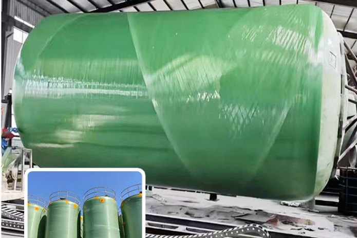
Most FRP equipment disputes are not fought over whether the tank holds liquid. They are fought over what the buyer was allowed to watch, what the fabricator was obliged to record, and which test data actually exists on paper when a nozzle starts weeping in year three. A factory acceptance test (FAT) is the mechanism that answers those questions before the equipment leaves the shop — but only if it is defined in the purchase order as a set of named inspection points, agreed acceptance criteria and a documentation package, rather than as the vague sentence "the buyer may attend final testing".
This guide is written for the buyer, the third-party inspector and the fabricator who has to satisfy both. It covers the document set that governs a shop test, the difference between a witness point and a hold point, what actually gets measured on a laminate in the shop, the arithmetic behind a hydrostatic test (and why an aggressive test multiplier can strain a corrosion barrier past its design limit), punch-list grading, and the release dossier. Where a figure comes from a code clause it is named; where it comes from a worked calculation it is shown.
1. What a FAT Decides — and What It Does Not
A shop FAT answers four questions and only four: is the geometry what was ordered, is the laminate what was designed, does the finished item hold pressure without leaking, and is the evidence complete enough that a third party can audit the answer later. It does not prove that the design is correct — that is the design report's job — and it does not substitute for installation checks such as foundation levelness, nozzle alignment to field piping or hydrotesting after site jointing.
The reason the distinction matters commercially is that a shop test is the last moment when the fabricator still has full control of access, water supply, lifting and repair facilities. Once a tank or vessel is on a truck, every subsequent correction is charged at field rates and is usually accompanied by a schedule argument. This is precisely why code frameworks push work into the shop: ASME RTP-1, for example, allows a maximum allowable working pressure of only 2 psig unless the as-constructed laminate receives a proof test, rising to 15 psig once that proof test has been performed. The test is not an administrative formality in that framework; it is what unlocks the pressure rating.
2. The Document Set That Governs the Test
An inspection and test plan (ITP) is a table, one line per inspection or test, that names the item or activity, the inspection method, the acceptance criterion, the record produced and the point type. Every clause in it must trace back to a purchase specification. Four documents form the chain:
| Document | Prepared by | What it fixes for the FAT |
|---|---|---|
| User's Basic Requirements Specification (UBRS) | Buyer | Design pressure and temperature, fluid and concentration, specific gravity, external loads, applicable code, service criticality. In ASME RTP-1 this is a mandatory input from the user before design starts. |
| Design report | Fabricator, certified by a qualified designer | Laminate schedule, thicknesses, design strain basis, nozzle reinforcement, support and anchor loads — the numbers the shop test verifies against. |
| Inspection and Test Plan (ITP) | Agreed between buyer and fabricator | Which checks are witnessed, which are hold points, which produce certificates and which are review-only. |
| Manufacturer's Data Report / conformity dossier | Fabricator | The signed record that the item was built to the approved design; in RTP-1 the report is signed by the fabricator's certifying individual and by the inspector. |
Two things go wrong here more often than anywhere else in the process. The first is an ITP that lists tests without acceptance criteria — "hydrostatic test to be carried out" is not an inspection line, because a pass/fail judgement is impossible. The second is a specification that quotes a national standard without naming an edition. Standards move: ASTM D2563, the long-standing practice for classifying visual defects in glass-reinforced plastic laminates, was withdrawn in 2024 with no direct replacement, and a reinstatement work item is pending. A purchase order that says "visual inspection per D2563" now points at nothing. Either attach the defect criteria as an appendix to the ITP or cite a controlled in-house standard. This is one of the few places in an FRP contract where the buyer's commercial protection genuinely depends on paperwork, not on engineering.
3. Witness, Hold and Review Points
The three point types are not interchangeable, and confusing them either wastes the buyer's money or hands the fabricator a schedule risk it did not agree to:
- Hold point (H) — work stops until the nominated party has inspected and signed. No notification, no progress. This is the strongest instrument and should be reserved for steps that can only be verified before they are covered up.
- Witness point (W) — the fabricator notifies the buyer, who may attend. If the buyer does not appear within the agreed notice period, the fabricator proceeds. Cost risk sits with the buyer.
- Review point (R) — a record is submitted for information or approval without any attendance. Used for mill certificates, laminate coupon test reports and calibration certificates.
An ITP that assigns H to everything is a document nobody can execute. Practical placement for FRP equipment is: corrosion barrier lay-up completion as a hold point (the barrier can never be inspected again from the inside), each structural layer count as a review point, Barcol and thickness mapping as witness points, hydrostatic test as a hold point for the pressure-hold data, and final visual and documentation as the release gate. For pipe spools and ducting, the equivalent is joint lamination inspection before the second application, plus a dimensional check on flange faces.
4. Laminate and Cure Verification in the Shop
Thickness and hardness readings are proxy measurements: they confirm that the lay-up sequence in the design report was actually executed and that the resin has reached a serviceable cure state. The three numbers that matter commercially are Barcol hardness, glass content and cure (Tg or residual cure).
| Check | Method | Typical shop criterion | Why it is in the FAT |
|---|---|---|---|
| Barcol hardness | ASTM D2583 (Europe: EN 59) | ≥ 90% of the resin manufacturer's specified minimum, measured on a clean, flat, prepared area | Detects under-cured laminate; a soft surface layer is the first sign of a wrong catalyst ratio, wrong shop temperature or a resin past its shelf life. |
| Glass content (burn-off) | ASTM D2584 (Europe: EN ISO 1172 calcination) | Corrosion barrier of a filament-wound tank: typically 27 ± 5% by weight; structural continuous roving 50–80% by weight | Low glass in the barrier means a resin-rich, chemically protective but mechanically weak layer; low glass in the structural layer means the thickness in the design report buys less strength than assumed. |
| Thickness | Calibrated contact gauge or ultrasonic, on a mapped grid | Not less than design thickness at any mapped point; recorded as a map, not as a single number | Local thin areas at knuckles, nozzles and support rings are where pressure equipment actually fails. |
| Laminate mechanical coupons | ASTM D638 tensile, ASTM D790 flexural, on a process-control or design-basis laminate | Values used in the design report, with the same resin and glass system as production | Ties the production laminate to the design allowables. Coupons taken from scrap of the same resin batch are the minimum acceptable evidence. |
| Glass transition / residual cure | DSC (ISO 11357-2) or the fabricator's documented cure schedule with temperature records | Tg at or above the design value; design temperature not above 180 °F (82 °C) in RTP-1 practice without special consideration | Cure determines chemical resistance and creep. Two laminates can pass a Barcol test and still differ in Tg by 20 K. |
| Chemical resistance coupon | ASTM C581 immersion, where the service fluid is aggressive | No unacceptable change in mass, dimension, appearance or hardness over the specified exposure | It is the only test that speaks to the actual chemical environment rather than to mechanical quality. |
A Barcol reading that passes on the outside of a laminate says nothing about the corrosion barrier on the inside, and vice versa. Map both faces, and record the date, ambient temperature and instrument state with every reading — a Barcol number without a temperature is not auditable evidence.
5. Hydrostatic Testing: Pressure, Strain and the Numbers Behind It
Water is the correct medium. Compressed air stores far more energy at the same pressure, and a laminate that fails under air can produce a genuine fragmentation hazard; compressed-air leak testing of FRP equipment belongs only at very low pressure, with strict exclusion zones, after the water test has been accepted.
The pressure to hold is where buyers most often over-specify. Multiplying the design pressure by 1.3 or 1.5 is a sound instinct borrowed from steel practice, but for FRP it must be checked against the strain the laminate will actually see, because the corrosion barrier has its own strain limit — in RTP-1 terms 0.13% where the resin elongation is at least 4%, otherwise 0.10% for sustained duty, with 0.20% allowed for intermittent duty, and the structural design factors set at 10 for sustained and 5 for intermittent load. Membrane hoop stress in a thin cylindrical shell is σ = p·D/(2t), and strain is that stress divided by the laminate modulus. Run the numbers on three realistic tanks:
| Vertical tank (full liquid head as design pressure) | Design pressure | Membrane strain at 1.00× | Membrane strain at 1.30× | Membrane strain at 1.50× | 1.50× as a share of a 0.10% barrier limit |
|---|---|---|---|---|---|
| DN3000 × 4500 mm, SG 1.2, t = 12 mm, E = 12 GPa | 53.0 kPa (7.7 psi) | 0.055% | 0.072% | 0.083% | 83% |
| DN2400 × 6000 mm, SG 1.8, t = 14 mm, E = 12 GPa | 105.9 kPa (15.4 psi) | 0.076% | 0.098% | 0.114% | 113% — over the limit |
| DN4000 × 4000 mm, SG 1.0, t = 16 mm, E = 14 GPa | 39.2 kPa (5.7 psi) | 0.035% | 0.046% | 0.053% | 53% |
The middle row is the instructive one. A dense, tall chemical tank designed with modest margin reaches the barrier's design strain during a 1.5× shop test, and exceeds the 0.10% barrier limit before the structural laminate is anywhere near distress. The equipment may well survive the test; the point is that the test itself consumes service life in the barrier, and a buyer who writes "1.5× design pressure" into an ITP without checking the strain basis is buying an unquantified debit against the corrosion protection. Agreement on the test multiplier should therefore be a documented conversation between design strain and test pressure, not a default number.
6. Where the Strain Actually Concentrates
Membrane strain is the easy half. The shell is a continuous cylinder, but real equipment has a shell-to-bottom knuckle, a skirt or support ring, a manway, a nozzle or two, and bolted cage ladders. Local bending and discontinuity stresses at those details routinely run two to three times the membrane value. Applied to the DN3000 tank above, a 1.5× test pressure produces 0.166% strain at a 2.0 discontinuity factor and 0.248% at 3.0 — well beyond any barrier design limit if the gauges happen to sit in the affected zone.
Two practical consequences follow:
- If strain gauges are used, their locations must be agreed in the ITP and must include at least one nozzle-to-shell junction and the bottom knuckle. Gauges only on the mid-shell barrel produce a reassuring number that does not describe the equipment.
- Where a nozzle or support detail cannot be strain-gauged, the mitigation is visual and dimensional: verify the reinforcement pad size against the design report, verify the fillet size at the joint, and record both. Reinforcement is checked by measurement, not by feel.
Two further shop-test variables are worth controlling explicitly. Freshly mixed tap water is normally acceptable, but the water temperature should be recorded: with the same DN3000 tank, laminate modulus retention falling from 100% at 20 °C to 85% at 60 °C moves the 1.5× test strain from 0.083% to 0.097%, which is 75% of the 0.13% limit rather than 64%. Hot fill water is not a neutral choice. Second, the fill and pressurisation rate should be specified: a 31.8 m ³ tank fills in about 3.2 hours at 10 m ³/h, so the slow final pressurisation phase is a small fraction of the total time and there is no schedule justification for rushing it.
7. Dimensional, Nozzle and Flange Checks
These are the cheapest checks on the ITP and the most expensive to fix in the field, because they are what the site piping and steelwork were designed around:
| Check | Method | Typical acceptance |
|---|---|---|
| Overall dimensions, straightness, roundness | Tape, laser or plumb line at agreed heights | Within the tolerance stated in the order or the referenced product standard; out-of-round measured at the same height at four quadrants |
| Nozzle location and orientation | Marked datums, angle measurements to a common reference | Position and angular deviation inside the piping flexibility allowance; the design report states the allowance |
| Nozzle projection and squareness | Square and straightedge on the flange face | Flange face square within the bolting clearance budget; enough projection for the gasket and bolt engagement |
| Bolt-hole straddle and alignment | Straightedge across both flanges | Holes straddle the vertical or horizontal centreline as drawn; mating holes align without forcing |
| Manway and cover fit | Trial assembly with the specified gasket | Cover seats without packing, bolt holes align, full gasket contact band |
| Support, lug and anchor locations | Measured against the foundation drawing | Bolt groups match the anchor plan; hold-down lugs present where buoyancy or wind uplift governs |
| Internal cleanliness | Visual, before the cover goes on | No loose cuttings, no sanding dust, no stray laminate scrap left in the shell |
Flange work deserves its own line in the ITP because it is where fabrication tolerance and site tolerance meet. A tank can be perfectly cylindrical and still unusable if a nozzle flange ends up 15 mm out of line with a fixed pipe run.
8. Acoustic Emission and Other Advanced Shop Checks
Acoustic emission (AE) examination monitors the laminate while it is being pressurised and listens for the release of energy from fibre breakage, matrix cracking and delamination. In the United States it is standardised as ASTM E1067 (E1067/E1067M), and it is an accepted supplementary examination for FRP tanks and vessels. Several codes treat it as an option for critical service rather than a default — RTP-1 lists acoustic emission among the additional measures for higher-consequence service, alongside verification testing and higher design factors.
AE is most useful when it is specified together with the pressure cycle that will produce meaningful emission: a fill-and-hold test of an unstressed vessel generates little data. Where AE is on the ITP, require the loading schedule, the sensor array drawing, the calibration source and the classification criteria to be submitted with the report, because an AE result without those four items cannot be independently reviewed. A related cost-effective alternative for large or field-built equipment is to perform the shop test on the sectional shell and then repeat the examination after site joint lamination — an approach covered in more detail in our guide to FRP tank field erection and joint lamination.
9. The Documentation Dossier for Release
Documentation is the part of a FAT that keeps working after everyone has gone home. A complete release dossier for FRP equipment normally contains:
| Item | Content | Typical timing |
|---|---|---|
| Approved design report and drawings | Laminate schedule, thickness, strain basis, nozzle details, support loads | Before fabrication starts |
| Material certificates | Resin type and batch, gelcoat/liner resin, glass products and lot numbers, catalyst, filler; traceability back to the store issue record | With the release dossier |
| Laminate test reports | Barcol map, thickness map, burn-off glass content, tensile/flexural coupons, Tg or cure records | With the release dossier |
| Pressure test record | Medium and temperature, pressure versus time chart, hold duration, gauge and calibration identifiers, strain data if used | Immediately after the test |
| Dimensional record | As-built dimensions, nozzle orientation table, flange squareness | With the release dossier |
| Non-conformance and repair records | Each deviation, its disposition, the repair procedure used and the re-inspection result | With the release dossier |
| Cleaning, preservation and packing record | Internal cleanliness, closure of all openings, transport brace or saddle arrangement | Before despatch |
Packing evidence deserves to be in the same dossier rather than a separate conversation, because transport damage is one of the most common causes of a "failed" arrival. The bracing, saddle layout and lifting arrangement that protect the laminate are described in our note on FRP equipment export packing and container loading, and the release record should show the arrangement actually used.
10. Punch Lists: Grading, Clearance and the Release Gate
A punch list is not a list of complaints; it is a graded action list with an owner and a clearance deadline. The version that works in practice uses three grades:
- Category A — items that affect pressure integrity, structural adequacy, chemical protection or safety. They must be cleared and re-inspected before the item is packed, and they must not be cleared by discussion.
- Category B — items that affect fit-up, function or durability at site, but not integrity: a missing nameplate, a cosmetic laminate defect, an incomplete support detail, an outstanding certificate. Clear before despatch where possible; otherwise clear before commissioning.
- Category C — documentary or cosmetic observations that can be closed during the warranty period, provided the date and the responsible party are named.
The release gate is then a simple rule: no Category A open, no Category B that affects lifting or transport, all required certificates present, and the manufacturer's data report signed. Writing the rule into the purchase order is what converts a punch list from a negotiation into a procedure.
11. Non-Conformances, Concessions and Repair Evidence
Every shop produces deviations, and a fabricator that reports none on a large order is either very good or not looking. What matters for the buyer is the disposition route and the evidence trail:
- A deviation is raised as a non-conformance with a written disposition: use as is, repair, or reject. "Use as is" requires a technical justification, not a schedule justification.
- Laminating repairs on a pressure-retaining or chemically exposed surface are re-work, not patching, and must repeat the original procedure: surface preparation by grinding to a defined profile, the same resin system, the same layer sequence, and re-testing by Barcol and, where relevant, re-hydrotesting.
- Any repair inside the corrosion barrier resets the expectations for that area. Ask for the repair extent to be mapped onto the same thickness grid used for the original survey, so that the next inspection has a baseline.
- A concession that reduces pressure rating, temperature rating or chemical service must be reflected in the nameplate and the data report. A concession that is not on the nameplate is a liability transfer with no consideration.
12. FAT Checklist Before You Sign the Release
- ITP revision matches the purchase order revision, and every line carries an acceptance criterion and a point type.
- Design report, drawings and laminate coupons reflect the same resin and glass system as production.
- Barcol and thickness maps exist for both faces of the laminate, with instrument and temperature recorded.
- Glass content results are reported separately for the corrosion barrier and the structural laminate.
- Pressure test record shows medium, temperature, pressure-time trace, hold duration and gauge calibration.
- Test multiplier was agreed against the laminate strain basis, not copied from a steel specification.
- Nozzle position, orientation, projection and flange squareness are recorded against tolerance.
- Acoustic emission, if specified, includes loading schedule, sensor layout, calibration and classification criteria.
- Repairs are documented with method, extent and re-inspection result, and are reflected on the nameplate where they change the rating.
- All Category A punch items are closed, and the manufacturer's data report is signed by both certifying and inspecting parties.
Two supporting documents are worth reading alongside this one. If the equipment is being built to a recognised vessel code, the certification routes and their class distinctions are set out in FRP vessels to ASME Section X and RTP-1. If acoustic emission is being considered as a shop or in-service examination, the testing sequence and acceptance logic are described in FRP tank acoustic emission testing to ASTM E1067. And for the stage that follows the FAT — receiving, positioning and site hydrotesting — see FRP storage tank transport and installation.
How Huangang Supports a Documented FAT
We build filament-wound tanks, process vessels and the production equipment that makes them, and we are set up to run a shop test against a buyer's ITP rather than against a verbal agreement. On equipment orders that means documented commissioning of the line itself — mandrel preparation, resin bath and tension settings — which is described in FRP filament winding machine commissioning and applies the same witness-point logic to machinery that this article applies to vessels.
For tanks and vessels we can supply the design report, the laminate test reports, the mapped thickness and Barcol records, the pressure test chart and a signed data report, and we will accept buyer-nominated witness or hold points at corrosion barrier completion, laminate completion, hydrostatic testing and pre-despatch packing. Send us the service conditions and the applicable code, and we will return a proposed ITP with the acceptance criteria filled in so that both sides are testing against the same numbers. Start from our filament-wound FRP storage tanks, our complete FRP production lines, or the specific CNC filament winding production line for tanks and pipes if the requirement is a factory rather than a single vessel.
Related reading: FRP tank nozzle and manway design for the reinforcement rules behind the dimensional checks, gel coat and corrosion barrier liner design for why barrier strain limits are set where they are, and FRP pipe installation and pressure testing for the field-side equivalent of the shop test.
Need help selecting FRP products?
Our engineers answer technical questions free of charge.
Ask an Engineer on WhatsApp