
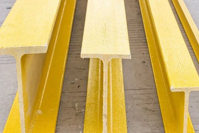
A pultruded FRP beam that passes every bending and deflection check can still fail at the point where the load gets in. Concentrated reactions, pipe shoes, cross-beam connections and column base plates all push load into the section through a small patch of flange, and in a pultruded shape that patch is bounded by a web-flange junction that is weaker than any of the laminates it connects. Two decades of laboratory testing have now produced workable hand-calculation models for web crushing, web buckling and junction failure, together with hard numbers on how much bearing plates and stiffeners actually buy you. This article walks through the three failure modes, the calculation models with worked numbers, and the detailing options that fix the problem — ending with a worked end-reaction check on a 250 mm I-beam.
1. Why Concentrated Loads Deserve Their Own Check in FRP
Structural steel has a yield plateau, so a heavily loaded web simply dents and redistributes. Pultruded glass-fibre-reinforced polymer does not. The material is linear-elastic to failure, which means there is no plastic reserve to smooth out stress concentrations at a load introduction point. Two further characteristics make the problem specific to pultrusion rather than composites in general:
- The web is a thin orthotropic plate loaded through its thickness. Its transverse (crosswise) modulus is typically one third of its longitudinal modulus — for a common web laminate, 9.7 GPa crosswise against 21.4 GPa lengthwise — so local bending and shear in the web plane mobilise the weak direction of the material.
- The web-flange junction is a manufacturing artifact, not a designed laminate. The junction region carries a roving-rich core and a resin-rich outside, and test coupons cut through a junction consistently measure lower strength than flat coupons cut from the same panel. The junction is where the load path must turn 90 degrees, and it is the weakest link on that turn.
The practical consequence: a designer who checks global bending, deflection and even panel-zone shear can still deliver a beam that fails at the first serious point load. Local checks at every load introduction are not optional in pultruded FRP; they are the design.
2. Three Failure Modes at a Load Introduction Point
Experimental work on pultruded I and wide-flange shapes loaded in the plane of the web has consistently identified three distinct mechanisms, and which one you get depends mainly on web slenderness and where the load sits:
| Failure mode | Where it initiates | Typical trigger | First-line remedy |
|---|---|---|---|
| Web crushing | Web laminate directly under (or beside) the bearing | Stocky webs, short bearing length, high contact stress | Wider or thicker bearing plate |
| Web buckling | Web plate buckles out of plane between flanges | Deep, thin webs; end reactions (ETF) worse than interior loads (ITF) | Vertical stiffeners to reduce the buckling panel width |
| Junction shear separation | Wedge-shaped shear crack at the web-flange junction | Almost every concentrated-load test on I-shapes to date | Bonded/bolted angles at the junction |
A 2021 direct-strength-method study of pultruded GFRP I-beams confirmed the pattern: as web slenderness increases, the governing mechanism shifts from web crushing through combined crushing-and-buckling to pure buckling. The three modes are not competing theories — they are a sequence, and each needs its own check.
3. What Twenty Tested Beams Actually Showed
The most cited data set is Borowicz and Bank's 2011 study in the Journal of Composites for Construction: twenty pultruded FRP I-shaped beams, nominal depths from 152 to 305 mm, tested in three-point bending at a span-to-depth ratio of four, with the load applied to the top flange directly above the web. Twelve beams had no bearing plate; eight had plates of varying width and thickness. The findings set the baseline for everything that follows:
- Every single specimen failed the same way — a wedge-like shear failure at the upper web-flange junction, not a crushing failure of the flat web.
- Bearing plates increased capacity by 35% or more, growing with plate width and thickness, and raised the average web shear stress at failure from 17.4 MPa to 27.2 MPa — still far below the 69 MPa in-plane shear strength of the material. The junction fails at roughly a quarter to two fifths of what the coupon data would suggest.
- A proposed design equation predicted capacity well: the average ratio of experimental to predicted capacity was 1.12 with a coefficient of variation of 0.10 across depths up to 305 mm.
The junction, not the flat of the web, is where pultruded beams die under concentrated load. Any check that only looks at web crushing or web buckling is checking the wrong bottleneck for most standard sections.
A follow-up programme on five 610 mm deep beams (two vinyl ester, three polyester resin) added the deep-web case: all five specimens experienced local web buckling first — on average at 90% of the ultimate load — followed by material failure in the loaded web-flange junction. Deep webs buckle; standard-depth webs go straight to junction shear.
4. The Material Numbers Behind the Checks
European practice anchors local checks to EN 13706, which sets grade minimums for pultruded profiles. The E23 and E17 grades are defined by the values in Table 4.1, measured on the standard coupons of EN 13706-2:
| Property | Test method | E23 minimum | E17 minimum |
|---|---|---|---|
| Full-section flexural modulus (GPa) | EN 13706-2 Annex D | 23 | 17 |
| Tensile modulus — axial (GPa) | EN ISO 527-4 | 23 | 17 |
| Tensile modulus — transverse (GPa) | EN ISO 527-4 | 7 | 5 |
| Tensile strength — axial (MPa) | EN ISO 527-4 | 240 | 170 |
| Tensile strength — transverse (MPa) | EN ISO 527-4 | 50 | 30 |
| Pin-bearing strength — axial (MPa) | EN 13706-2 Annex E | 150 | 90 |
| Pin-bearing strength — transverse (MPa) | EN 13706-2 Annex E | 70 | 50 |
| Flexural strength — axial (MPa) | EN ISO 14125 | 240 | 170 |
| Flexural strength — transverse (MPa) | EN ISO 14125 | 100 | 70 |
| Interlaminar shear strength — axial (MPa) | EN ISO 14130 | 25 | 15 |
Two cautions apply. First, the pin-bearing values are for bolted holes — a pin pressed against the wall of a drilled hole. A seated plate bearing on the flange surface is through-thickness compression, a different (and generally milder) state; do not apply the 150/70 MPa numbers to it. Second, EN 13706 does not specify a transverse compressive strength for the web, which the web-crushing model needs. Manufacturer coupon data fills that gap — for example, the Pultex design manual lists a crosswise compressive strength of 14,200 psi (97.9 MPa) for the web coupon of its 1525-series laminates. That is the value used in the worked numbers below, and the right value for your project is the certified coupon value from your own pultruder.
5. Web Crushing: The Effective-Length Model You Can Calculate
The first-generation design models in Bank's Composites for Construction and in the Eurocomp handbook treat web crushing as a contact problem: the bearing spreads through the web at 45 degrees, so the effective resisting area is the web thickness times an effective length that grows with the bearing length. With the section symbols below, the model is compact enough for a spreadsheet:
- Clear web depth: hw = h − 2tf − 2R, where h is section depth, tf flange thickness and R the web-flange junction radius.
- Effective length: beff = ss + hw/2 for an end reaction (ETF — end two flange loading), and beff = ss + hw for an interior load with a matching reaction opposite (ITF — interior two flange). Eurocomp words the same rule as "bearing length plus a 45° dispersion through half the web height."
- Crushing capacity: Fcrush = σcrush · tw · beff, with σcrush the transverse compressive strength of the web laminate.
Table 5.1 applies the model to a 250 × 125 × 9.5 mm I-section (hw = 219 mm, tw = 9.5 mm, σcrush = 97.9 MPa). Capacities are characteristic values — apply your project's factor of safety or resistance factor on top.
| Bearing length ss (mm) | beff ETF (mm) | PETF (kN) | beff ITF (mm) | PITF (kN) |
|---|---|---|---|---|
| 0 (no plate) | 109.5 | 101.8 | 219.0 | 203.7 |
| 50 | 159.5 | 148.4 | 269.0 | 250.2 |
| 100 | 209.5 | 194.9 | 319.0 | 296.7 |
| 150 | 259.5 | 241.4 | 369.0 | 343.2 |
The table shows why bearing length matters so much: going from a knife-edge to a 100 mm plate multiplies the crushing capacity by roughly 1.9 at an end reaction. It also shows why end locations are always the critical ones — the ITF case has twice the dispersion length, so it is inherently stronger at equal bearing length.
6. Web Buckling: When Slenderness Takes Over
For deeper sections the web fails as a plate before it fails as a material. The expression that best matched the 610 mm beam tests — and which has been proposed for inclusion in the updated Italian guide CNR-DT 205 — treats the web as an orthotropic plate simply supported at its edges:
floc = [π²·√(EL·ET) / 12(1−νLTνTL)] · (tw/bw)² · (2 + 4bw²/a²)
Floc = floc · tw · a
where bw is the clear web depth, a is the lesser of the web depth and the spacing of vertical web stiffeners (a = bw when unstiffened), EL and ET are the web laminate moduli in the lengthwise and crosswise directions, and ν are the corresponding Poisson ratios. The measured-to-predicted ratio averaged 1.11 (1.24 for vinyl ester, 1.02 for polyester) with a coefficient of variation of 0.11 — respectable accuracy for a closed-form plate formula.
Table 6.1 evaluates the formula with the same web coupon properties as Section 5 (EL = 21,374 MPa, ET = 9,653 MPa, νLTνTL = 0.042), comparing a standard 250 mm section against a hypothetical 600 mm deep web of equal thickness:
| Case | bw (mm) | a (mm) | floc (MPa) | Floc (kN) |
|---|---|---|---|---|
| 250-deep, unstiffened (a = bw) | 219 | 219 | 139.2 | 289.7 |
| 600-deep, unstiffened (a = bw) | 554.6 | 554.6 | 21.7 | 114.4 |
| 600-deep, stiffeners at 300 mm | 554.6 | 300 | 56.7 | 161.6 |
| 600-deep, stiffeners at 150 mm | 554.6 | 150 | 205.1 | 292.3 |
Read the floc column against the 97.9 MPa crushing stress and the design logic falls out by itself. For the 250 mm web, the buckling stress (139 MPa) exceeds the crushing stress, so material failure governs and stiffeners buy little. For the 600 mm web, the buckling stress (21.7 MPa) is a quarter of the crushing stress, so stability governs — and vertical stiffeners that reduce a from 554 mm to 300 mm lift capacity by 41%, or to 150 mm by 2.6 times. Note the subtlety: stiffeners spaced wider than the web depth change nothing, because a is capped at bw.
7. Bearing Plates: The Cheapest Capacity You Can Buy
Across the 2011 test programme, adding a bearing plate under the concentrated load increased capacity by 35% or more, scaling with plate width and thickness. The mechanism is dispersion: a wider, stiffer plate pushes the 45-degree spread wider before the load reaches the junction, enlarging beff in exactly the way the crushing model predicts. It also raised the average web shear stress at failure from 17.4 to 27.2 MPa — a 56% increase in the stress the junction could mobilise before the wedge crack ran.
Practical detailing notes from the same body of work:
- The plate should be at least as wide as the flange and long enough to mobilise the dispersion — plates that are wider and thicker both helped in testing.
- A steel plate bonded or bolted to the flange also protects the pultruded surface from local abrasion under vibrating loads.
- Plate seating must remain flat: shimming a rocking plate creates exactly the line contact the plate was meant to remove.
For a seated plate on the flange surface, contact stress is through-thickness compression and rarely governs against material strength; the checks that matter remain web crushing, web buckling and junction shear.
8. Stiffeners: Angles at the Junction Beat Doublers
When a plate is not enough, the 2013 follow-up study compared three strengthening systems on pultruded I-beams under concentrated load, and the ranking was unambiguous:
| Strengthening option | Ultimate capacity increase | Prevents junction failure? |
|---|---|---|
| Full-depth web bearing stiffeners | > +50% | Partially |
| Stiffening angles at the loaded web-flange junction | > +50% | Yes — the only option that did |
| "Doubler" plates on the web | +31.7% | No |
Junction angles win because they attack the actual bottleneck: they add bonded material along the junction line, enlarging the shear area that the wedge crack must cross and carrying the load turn that the bare junction performs so poorly. Doublers thicken the web flat — which was not failing — and therefore deliver the least gain.
There is currently no standardised coupon test that gives you a design value for the web-flange junction. Junction specimens cut from real profiles measure roughly half the strength of flat coupons from the same region — the roving-rich core at the junction is the reason. Until that changes, junction capacity comes from test data and manufacturer guidance, not from a generic material table.
Two further options exist for extreme load introductions. Concrete infill of a pultruded section between the flanges prevents web buckling outright and raised ultimate bending capacity by 100–141% in hollow-section tests — a common solution for bridge decks. And for repeated heavy loads, spreading the reaction through a full-depth bearing stiffener pair (Section 6) keeps the junction out of the load path entirely.
9. A Worked End-Reaction Check
Put the tools together on the 250 × 125 × 9.5 mm I-section carrying a service end reaction of 45 kN (ULS 67.5 kN at 1.5). The bearing detail is a 100 mm seat plate; the web is unstiffened, so a = bw = 219 mm.
| Check | Capacity basis | Characteristic capacity | Demand (ULS) | Utilisation |
|---|---|---|---|---|
| Web crushing (ETF) | σcrush·tw·(ss+hw/2), σ = 97.9 MPa | 194.9 kN | 67.5 kN | 35% |
| Web buckling | floc·tw·a, floc = 139.2 MPa | 289.7 kN | 67.5 kN | 23% |
| Junction (avg web shear) | V/(tw·hw) vs 17.4 MPa observed failure stress, unstiffened | 17.4 MPa basis | 21.6 MPa | 124% — fails |
| Junction with bonded angles | 17.4 MPa × 1.5 (+50% per 2013 campaign) | 26.1 MPa basis | 21.6 MPa | 83% — OK |
The two textbook checks pass with wide margins, and the beam still fails — exactly as the twenty test beams did. The average web shear at the support is V/(tw·hw) = 45,000 N / (9.5 mm × 219 mm) = 21.6 MPa at service load, above the 17.4 MPa at which unstiffened specimens actually failed. The honest reading of the last two rows: junction capacity has no code-issued allowable, so the check is made against published test data, and the fix is bonded junction angles. Specify them at both loaded and support positions and the same reaction passes with margin. This comparison is indicative, not a substitute for a project-specific assessment against the pultruder's certified junction values.
10. Specification Checklist for Load Introduction Details
Most web-crippling problems are specified away for pennies at the drawing stage. A purchase specification that includes the following items will screen out the failures before they are fabricated:
- Mark every load introduction — reactions, point loads, jack points and pipe shoes — on the fabrication drawing, with service and ultimate values.
- Require the web coupon values (crosswise compressive strength, lengthwise/crosswise moduli, Poisson ratios) for the actual laminate, not catalogue generic properties.
- Ask for junction test data or a stated junction design value from the pultruder; if none exists, require a load test on a representative beam and bearing detail.
- Set minimum bearing plate dimensions (width, length, thickness) at each introduction, and require full flat seating — no shimming of line contact.
- Specify bonded/bolted junction angles at supports and concentrated loads where the junction check governs, with the adhesive system named.
- Add vertical stiffeners where a deep web buckles, and remember that spacing beyond the web depth gains nothing.
- State the acceptance basis: capacity predicted by the effective-length crushing model and the plate-buckling expression above, verified against measured coupon and junction data.
For the ASCE side of the Atlantic, the LRFD for Pultruded FRP Structures standard (developed from the ACMA pre-standard finalised in November 2010) now gives designers a consensus framework for member and connection design, and manufacturer design manuals fill the product-specific values. Whichever framework governs your project, the local checks in this article ride on top of it — they are the ones the global checks never see.
Talk to an Engineer About Your Load Path
If your structure has concentrated reactions on pultruded beams — pipe racks, equipment skids, bridge decks, mezzanine framing — send us the loads, section sizes and bearing details. We will run the crushing, buckling and junction checks with our certified laminate data and come back with a bearing and stiffening detail that passes, normally within one working day.
Related reading: FRP Structural Bolted Connections: Bolt Grades, Edge Distance and Bearing Design · Pultruded FRP Compression Members: Local Buckling and Effective Length · Pultruded FRP Trusses and Space Frames: Node Detailing · FRP Grating and Profile Machining: Drill Speeds and Edge Sealing · Product pages: Pultruded FRP I-beam / H-beam structural support · High-strength FRP I-beam · Pultruded fiberglass structural profiles
Need help selecting FRP products?
Our engineers answer technical questions free of charge.
Ask an Engineer on WhatsApp