
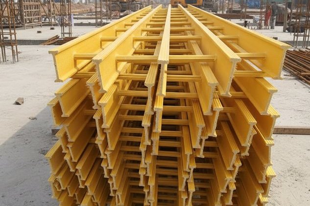
A pultruded FRP column fails in one of three ways, and which one it is depends almost entirely on its length rather than on its material. A short member crushes or buckles locally in a flange or a wall. A long member buckles as a whole, at a load that is well below what Euler predicts unless the shear flexibility of the material is accounted for. In between, the two modes interact, and the interaction is the part that designers most often ignore — usually by taking the lower of the two loads and calling it conservative, which it is not, because the real capacity in the transition range can fall below both. This guide sets out the material basis, the local and global buckling checks, the shear correction that costs a closed tube four per cent and an open section fifteen, the transition slenderness for two standard tube sizes, the interaction equation and its uncertainty band, and the load factors that reduce a sustained-load column to a fraction of its short-term capacity.
1. Why an FRP Column Is Not a Steel Column
The instinct when a column is specified is to reach for a steel code. Doing that with pultruded FRP produces answers that are wrong in both directions at once, and the reasons are structural rather than a matter of a different safety factor.
- The modulus is roughly a tenth of steel's. Euler buckling load scales directly with the modulus, so an FRP column of the same section buckles at about a tenth of the steel load. Section depth becomes worth far more than material strength.
- The material is strongly orthotropic. The transverse modulus is only about a quarter of the longitudinal value and the in-plane shear modulus about an eighth. Plate buckling and shear deformation both feel those directions, so an isotropic formula fitted to the longitudinal modulus alone over-predicts.
- Shear deformation is not negligible. Steel columns deflect by bending; FRP columns deflect by bending and by shear, and at the slendernesses used in practice the shear share is several per cent to more than twenty.
- Creep under sustained load is a design load case. A column carrying a permanent load does not have the strength it has in a short-term test, and the code expresses this through a separate factor rather than through the resistance factor.
- The section is thin-walled. Local plate buckling competes with global buckling across the whole practical range, not only at very short lengths.
2. Material Basis
The design values below are the minimum characteristic properties that the governing standard requires a pultruded shape to demonstrate before it can be designed to that standard. Using them makes the resulting numbers a floor rather than a prediction for any particular supplier's product.
| Property | Minimum required | SI equivalent |
|---|---|---|
| Longitudinal tensile strength | 30,000 psi | 207 MPa |
| Transverse tensile strength | 7,000 psi | 48 MPa |
| Longitudinal compressive strength | 30,000 psi | 207 MPa |
| Longitudinal tensile and compressive modulus | 3.0 x 10⁶ psi | 20.7 GPa |
| Transverse tensile and compressive modulus | 0.8 x 10⁶ to 1.0 x 10⁶ psi | 5.5 to 6.9 GPa |
| In-plane shear strength | 8,000 psi | 55 MPa |
| In-plane shear modulus | 0.4 x 10⁶ psi | 2.76 GPa |
| Interlaminar shear strength | 3,500 psi | 24 MPa |
| Longitudinal pin-bearing strength | 21,000 psi | 145 MPa |
Three further requirements matter to a compression member in ways that are easy to overlook. The glass transition temperature must be above 82 degrees Celsius, and the permitted service temperature is that value minus 22 kelvin, which puts the ceiling for a minimum-grade pultrusion at 60 degrees. The Barcol hardness must exceed 40, which is a cure check rather than a strength property but one that a member in sustained compression depends on. And the material must retain at least 75 per cent of its strength after damp heat, ultraviolet exposure and freeze-thaw cycling: a column that has been weathered is not the column that was tested.
Europe works from the EN 13706 grade system, in which E17 and E23 denote increasing minimum modulus and strength, and from the design technical specification that sits alongside the Eurocodes. North America works from the LRFD standard that replaced the earlier pre-standard. China works from its own composite structures standard with an accompanying technical regulation for pultruded profiles. The three use different resistance factors and different caps on long-term stress, so a section checked to one and specified to another is not a checked section.
3. Three Failure Modes
Material crushing governs only very short members or members that are fully restrained against buckling. It is a stress check against the longitudinal compressive strength, reduced by a resistance factor.
Local plate buckling governs short to intermediate members. A flange or a wall behaves as a thin plate in compression and buckles at a stress that depends on the square of its width-to-thickness ratio, on the longitudinal modulus, and on the rotational restraint along its edges. Because the width-to-thickness ratio is squared, it is the most sensitive variable in the whole design.
Flexural buckling governs long members. It is the classical Euler mode, modified by the fact that the material also shears.
4. Local Buckling and the Width-to-Thickness Screen
The plate buckling stress for an orthotropic plate takes the familiar thin-plate form with two corrections: a coefficient that accounts for the orthotropy, and a plate coefficient that depends on how the edges are restrained.
- sigma_cr = 0.8 k pi2 E_L / (12 (1 - nu_LT nu_TL)) x (t / b)2
- k = 4.0 for a plate restrained along both edges — a box wall, or a flange that is part of a closed section.
- k = 0.5 for an outstanding element with one free edge — the projecting half of an I-section flange, or a leg of an angle.
- The coefficient 0.8 is the orthotropic correction; nu_LT is 0.30 and nu_TL is the minor Poisson ratio, about 0.08.
| Section | Plate | Effective width | t / b | k | Buckling stress | What governs |
|---|---|---|---|---|---|---|
| 152 x 152 x 6.4 box | Box wall | 139.2 mm | 0.0460 | 4.0 | 118.0 MPa | Local buckling |
| 152 x 152 x 6.4 box | Outstanding | 76.0 mm | 0.0842 | 0.5 | 49.5 MPa | Local buckling |
| 152 x 152 x 9.5 box | Box wall | 133.0 mm | 0.0714 | 4.0 | 284.8 MPa | Material strength |
| 152 x 152 x 9.5 box | Outstanding | 76.0 mm | 0.1250 | 0.5 | 109.0 MPa | Local buckling |
Two things stand out. The first is the gap between the two tube sizes: going from a 6.4 mm wall to a 9.5 mm wall raises the local buckling stress from 118 MPa to 285 MPa, past the 207 MPa material strength, so the thicker tube is governed by crushing rather than by plate buckling. A 50 per cent increase in wall thickness removes local buckling as the governing mode entirely. The second is the ratio between the two plate coefficients: the same tube checked as an outstanding element rather than a restrained plate buckles at 42 per cent of the stress. Whether a wall counts as restrained in compression is worth much more than whether the wall is thick.
That is why the practical screen is the width-to-thickness ratio. For an E-glass pultruded section the advisory limit for an outstanding element is about 18. The 6.4 mm tube at a ratio of 23.75 fails the screen; the 9.5 mm tube at 16.00 passes it. The screen is a first pass, not a substitute for the calculation, and the limit tightens for compression members because a column tolerates less local instability than a beam.
5. Flexural Buckling and the Shear Correction
Euler gives the flexural buckling load of a perfect pin-ended column as P_E = pi2 E I / (K L)2. For pultruded FRP that is an upper bound, because the member also deflects in shear. The Engesser correction accounts for it:
- P_G = P_E / (1 + P_E / (A_s G)), where A_s is the shear area in the buckling plane and G is the shear modulus.
- For a closed square tube, the whole section resists shear, so A_s is essentially the full area and the correction is small.
- For an open I-section, only the web resists shear in the plane of buckling, so A_s is a fraction of the area and the correction is large.
| Effective length K L | K L / r | Euler P_E | Engesser P_G | Shear loss | Which mode |
|---|---|---|---|---|---|
| 152 x 152 x 6.4 closed tube, A_s = full area | |||||
| 1.5 m | 25.2 | 1,198 kN | 1,073 kN | 10.4 per cent | Local buckling |
| 2.0 m | 33.6 | 674 kN | 633 kN | 6.1 per cent | Local buckling |
| 2.5 m | 42.0 | 431 kN | 414 kN | 4.0 per cent | Flexural buckling |
| 3.0 m | 50.4 | 300 kN | 291 kN | 2.8 per cent | Flexural buckling |
| 4.0 m | 67.2 | 169 kN | 166 kN | 1.6 per cent | Flexural buckling |
| 5.0 m | 84.0 | 108 kN | 107 kN | 1.0 per cent | Flexural buckling |
| 6.0 m | 100.8 | 75 kN | 74 kN | 0.7 per cent | Flexural buckling |
| 152 x 152 x 9.5 closed tube, A_s = full area | |||||
| 2.0 m | 34.3 | 940 kN | 885 kN | 5.9 per cent | Flexural buckling |
| 3.0 m | 51.5 | 418 kN | 407 kN | 2.7 per cent | Flexural buckling |
| 4.0 m | 68.6 | 235 kN | 231 kN | 1.5 per cent | Flexural buckling |
| 5.0 m | 85.8 | 150 kN | 149 kN | 1.0 per cent | Flexural buckling |
| Nominal 152 x 152 x 6.4 I-section, A_s = web only | |||||
| 2.0 m | 29.3 | 674 kN | 529 kN | 21.5 per cent | Flexural buckling |
| 2.5 m | 36.7 | 431 kN | 367 kN | 14.9 per cent | Flexural buckling |
| 3.0 m | 44.0 | 300 kN | 267 kN | 10.9 per cent | Flexural buckling |
| 4.0 m | 58.6 | 169 kN | 158 kN | 6.4 per cent | Flexural buckling |
| 5.0 m | 73.3 | 108 kN | 103 kN | 4.2 per cent | Flexural buckling |
The pattern is what the theory predicts and what the field reports confirm. A closed tube loses four per cent at two and a half metres and under two per cent beyond four metres. An open I-section of the same envelope and the same bending stiffness loses fifteen per cent at two and a half metres and eleven per cent at three metres. That is the whole argument for using tubes rather than open sections in a long compression member: not that the tube is stronger in bending, since the two have the same I in this comparison, but that the tube does not shear.
A designer who checks an FRP column with Euler alone will overstate the capacity of a closed tube by a few per cent and the capacity of an open I-section by ten to twenty per cent. The error is concentrated exactly in the slenderness range where most real columns sit.
6. Where Local Buckling Hands Over
Setting the local buckling load equal to the shear-corrected Euler load gives the transition slenderness, and it is a useful number to carry in your head because it tells you which check to do first.
| Section | Local buckling load | Local buckling governs below | In terms of K L / r |
|---|---|---|---|
| 152 x 152 x 6.4 box | 440 kN | K L = 2.42 m | 40.7 |
| 152 x 152 x 9.5 box | 1,121 kN (capped at material strength) | K L = 1.76 m | 30.2 |
The second row is worth reading carefully. The 9.5 mm tube reaches its transition at a shorter length than the 6.4 mm tube, which looks wrong until you remember that the local buckling stress of the thicker tube is above the material strength. Its local capacity is a crushing capacity, not a plate buckling capacity, and it is high; the column therefore has to be very short before local behaviour governs. A stocky tube is a crushing-governed member at almost every practical length.
7. Interaction Between the Two Modes
Choosing the lower of the local and global loads is not conservative in the transition range. The two modes interact, and the capacity falls below both. The widely used form comes from a non-dimensional slenderness and an empirical interaction constant:
- lambda = K L x sqrt(P_L / (E I pi2)), where P_L is the local buckling load and E I the bending stiffness.
- q = P_cr / P_L = (1 + 1/lambda2) / (2c) - sqrt( ((1 + 1/lambda2) / (2c))2 - 1 / (c lambda2) )
- c is a shape and imperfection constant. At c = 0 the interaction is linear and fully conservative; at c = 1 there is no interaction at all.
| K L | lambda | P_cr at c = 0.3 | P_cr at c = 0.5 | P_cr at c = 0.7 | P_cr at c = 1.0 |
|---|---|---|---|---|---|
| 1.0 m | 0.40 | 393 kN | 404 kN | 417 kN | 440 kN |
| 1.5 m | 0.61 | 343 kN | 362 kN | 385 kN | 440 kN |
| 2.0 m | 0.81 | 289 kN | 309 kN | 338 kN | 440 kN |
| 3.0 m | 1.21 | 193 kN | 207 kN | 227 kN | 300 kN |
| 4.0 m | 1.62 | 130 kN | 137 kN | 147 kN | 169 kN |
| 5.0 m | 2.02 | 91 kN | 95 kN | 99 kN | 108 kN |
Read the two-metre row against the pure local capacity of 440 kN and the pure global capacity of 414 kN. The interaction at a mid-range value of c gives 309 kN, which is 25 per cent below the lower of the two single-mode answers. The uncertainty band between c = 0.3 and c = 0.7 is itself wide — 289 to 338 kN at that length — which is the honest position: the intermediate range of an FRP column is where the prediction is weakest and where a prototype test earns its cost. Above lambda of about 1.5, which corresponds to four metres here, the two extremes converge and the interaction stops mattering.
8. Design Strength and the Load Factors
The resistance is factored twice, once for the failure mode and once for the nature of the load. Local buckling takes the higher resistance factor because it is a more predictable mode; global buckling takes the lower one because it is sensitive to crookedness and end conditions. Then a time effect factor is applied according to the dominant load type, and for a permanent load that factor is far below one.
P_design = lambda x phi x P_n, with phi = 0.80 for local buckling and 0.70 for global buckling.
| K L | phi x P_n | Permanent | Storage | Live | Snow, rain | Wind, seismic | Live with impact |
|---|---|---|---|---|---|---|---|
| 152 x 152 x 6.4 box, kN | |||||||
| 1.0 m | 352 | 141 | 211 | 281 | 264 | 352 | 352 |
| 2.0 m | 352 | 141 | 211 | 281 | 264 | 352 | 352 |
| 3.0 m | 204 | 82 | 122 | 163 | 153 | 204 | 204 |
| 5.0 m | 75 | 30 | 45 | 60 | 56 | 75 | 75 |
| 152 x 152 x 9.5 box, kN | |||||||
| 1.0 m | 897 | 359 | 538 | 717 | 673 | 897 | 897 |
| 2.0 m | 619 | 248 | 371 | 495 | 464 | 619 | 619 |
| 3.0 m | 285 | 114 | 171 | 228 | 213 | 285 | 285 |
| 5.0 m | 104 | 42 | 63 | 83 | 78 | 104 | 104 |
The permanent load column is the one that catches people out. A three-metre 9.5 mm tube in a structure carrying nothing but permanent load has 114 kN available, not 285 kN — a factor of 2.5 lost to creep, before any load factors on the demand side. This is why FRP structures carrying sustained load need larger sections than a short-term strength comparison suggests, and it is the single most common reason a design that looks fine on a datasheet fails to check out.
9. Limits That Invalidate the Check
The calculation above is only valid inside its own envelope. Four limits matter.
- Service temperature. The permitted temperature is the glass transition temperature minus 22 K. At the minimum permitted Tg of 82 degrees the ceiling is 60 degrees. Above it the modulus falls and the creep rate rises, and neither the buckling load nor the time effect factor remains valid.
- Slenderness. Compression members are conventionally limited to a slenderness ratio of 150. For the two tubes above that corresponds to an effective length of about 8.9 m. Beyond it the member is governed by handling and by second-order effects rather than by buckling.
- Width-to-thickness. A section over the advisory ratio can still be used, but only with the local buckling check done explicitly, and never by assuming full material strength.
- Environmental retention. A member that has been through damp heat, ultraviolet and freeze-thaw cycling retains a fraction of its strength, and the design values already assume a retention of at least 75 per cent. A member in a chemical plant or a coastal location needs the retention data for that environment, not the generic figure.
10. End Conditions and Effective Length
K is where a correct calculation and a bad assumption meet. The recommended values for pultruded columns follow the classical set, and the difference between the best and worst case is a factor of more than three in capacity, because capacity varies with the square of K.
| End condition | Recommended K |
|---|---|
| Pinned both ends | 1.00 |
| Fixed both ends, no translation | 0.65 |
| Pinned one end, fixed the other | 0.80 |
| Fixed with translation fixed at both ends | 1.20 |
| Fixed with translation free (cantilever) | 2.10 |
| Pinned with translation fixed | 2.00 |
Two cautions apply specifically to FRP. The first is that a bolted end connection rarely delivers the fixity a steel detail would, because the connection stiffness is limited by the laminate's pin-bearing and transverse properties rather than by the bolt. A connection drawn as fixed but built with a single row of bolts behaves as pinned. The second is that the bracing that prevents translation has to be designed as a load path, not assumed: lateral restraint that relies on a cladding panel or a handrail that was never checked for the bracing force will move, and K will become whatever the connection permits rather than what the drawing claims.
11. FAQ
Can I use the Euler formula if I add a large safety factor? It is better to apply the shear correction and keep the factor for what it is for. A blanket factor that covers shear deformation at four metres will be grossly over-conservative at eight metres and still under-conservative for an open section at two.
Is a closed tube always better than an I-section for a column? For buckling alone, yes, because the tube shears less and its walls are better restrained. The exception is where the column also carries bending or where the connection has to be made into a flat face, and there the I-section can win on detailing even though it loses on buckling.
Why is the local buckling stress capped at the material strength? Because the plate will not buckle at a stress the material cannot reach. When the calculated plate buckling stress exceeds the compressive strength, the member fails by crushing and the local buckling check drops out of the governing set.
Does the interaction calculation replace a prototype test? No. Its uncertainty band in the transition range is wide, and the constants are calibrated per section type. An interaction calculation tells you what the code requires and where the risk sits; a column test tells you what the section actually does.
Do the same rules apply to a beam? Not directly. A beam has the compression flange stabilised by its own tension flange to a degree that a column does not, so the local buckling coefficients and the interaction treatment differ. The plate buckling equations are shared; the interaction and the resistance factors are not.
12. Designing FRP Columns That Check Out
At Henan HuanGang we produce pultruded fibreglass structural profiles for construction and building applications across the standard wide-flange, square tube, channel and angle range, and the questions that come up most often are exactly the ones in this guide: which mode governs at a given length, whether the wall is restrained enough to count as a plate, and what the sustained-load factor does to the answer. Send us the member length, the end conditions, the load type and the service environment, and we will come back with the section, the governing mode and the design capacity — and, if the member falls in the interaction range, we will say so rather than hand you a single number with no range on it.
Related reading: pultruded FRP profiles in structural applications, bolted connections in FRP structures, adhesive bonding of FRP structural joints, pultruded FRP trusses and space frames, custom pultruded profiles, FRP compared with wood and aluminium structures, pultruded FRP solar mounting structures, pultruded FRP window and facade frames, FRP cable tray in corrosive environments and UV weathering and colour stability of FRP.
Need help selecting FRP products?
Our engineers answer technical questions free of charge.
Ask an Engineer on WhatsApp