
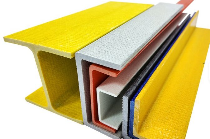
A pultruded FRP truss almost never fails in the middle of a chord. It fails at a node — at a bolt hole, at a lap that was detailed like a steel connection, at an end distance that was copied from a steel table. That is the direct consequence of how the material is made: pultrusion pulls continuous glass along one axis, so the profile is strong and stiff lengthwise and behaves like a much weaker, far more flexible material in every other direction. An EN 13706 E23 profile that is certified at 240 MPa in axial tension is only certified at 50 MPa across the section, and its pin-bearing strength falls from 150 MPa axially to 70 MPa transversely.
This guide works through a complete parallel-chord truss from load case to bolt selection, using published design values from ASCE/SEI 74-23 and EN 13706-3:2002. It covers the three checks that actually govern FRP trusses — compression buckling of the chord, deflection including creep, and the bolted node — and it shows the arithmetic for a 6 m example so you can see where the numbers come from rather than take them on trust.
1. Why Truss Geometry Suits FRP — and Where It Punishes You
A truss is an efficient way to use a stiffness-poor material, because it converts bending into axial force. Instead of needing the section modulus a beam requires, a truss puts the two chords in near-pure axial load at a lever arm equal to the truss depth. A 0.75 m deep truss has four times the lever arm of a 375 mm deep beam of the same material and mass.
Three consequences follow, and they shape every design decision in this article:
- Deflection, not stress, sets the size. Pultruded GFRP has a longitudinal modulus of 17–23 GPa against roughly 200 GPa for steel. Any member sized for strength alone will be far too flexible. The practical rule is to close the deflection check first and let it drive the section.
- Buckling governs the compression chord. The chord is slender, the modulus is low, and the axial stress that causes Euler buckling is proportional to E. A chord that shows a comfortable stress utilisation against a 240 MPa tensile strength can be at 60% of a buckling allowable that is a third of that value.
- The nodes become the weak links. Every truss concentrates force into small areas at the joints. In a material with one strong axis, those concentrated forces land in the weak direction.
Design order that works for pultruded FRP trusses: establish the deflection limit first, then size the chords for buckling, then size the webs for tension, and only then detail the nodes. Reversing that order produces a frame that is strong enough and 40% too flexible.
2. The Design Basis: Two Standard Families, Two Sets of Numbers
Quote the standard you are designing to on the drawing, because the two main families do not give identical values and a supplier's datasheet may quote one, the other, or neither.
| Property at 23 °C | ASCE/SEI 74-23 minimum (US) | EN 13706-3:2002 E23 (EU) |
|---|---|---|
| Longitudinal tensile strength | 30,000 psi (207 MPa) — profiles; 20,000 psi for flat sheet | 240 MPa |
| Transverse tensile strength | 7,000 psi (48 MPa) | 50 MPa |
| Longitudinal compressive strength | 30,000 psi (207 MPa), ASTM D6641 | Not a required grade value; reportable per EN ISO 14126 |
| In-plane shear strength | 8,000 psi (55 MPa), ASTM D5379 | Interlaminar shear 25 MPa axial, EN ISO 14130 |
| Pin-bearing strength (axial / transverse) | 21,000 psi (145 MPa), ASTM D953 | 150 MPa / 70 MPa, Annex E of EN 13706-2 |
| Full-section flexural modulus | Not a grade criterion; use the product datasheet | 23 GPa minimum |
| Barcol hardness | Above 40, ASTM D2583 | Not specified in Part 3 |
| Glass transition temperature | Above 82 °C (180 °F), ASTM E1640 | Not specified in Part 3 |
| Durability retention | At least 75% of characteristic values after damp heat, UV and 100 freeze–thaw cycles | Water absorption at 24 h not more than 1.0% (E23) |
Two practical notes on reading that table. First, the EN grade number is the minimum full-section flexural modulus in gigapascals — E23 means 23 GPa, E17 means 17 GPa. Stiffness is the graded property precisely because it governs. Second, in practice E17 profiles cluster in the 3–5 mm wall range and E23 above 5 mm, because a thicker wall is what makes the higher modulus achievable. If a supplier offers a thin-walled section at E23, ask for the full-section test to Annex D of EN 13706-2, not a coupon test.
3. Applying the Environmental and Time-Effect Factors Before You Size Anything
Raw strength is a laboratory number. FRP loses a large fraction of it in service, and the design standards formalise that loss in two separate places: an environmental knockdown applied to the reference strength, and a time-effect factor that depends on how long the load sits on the structure.
| Dominant load | Time-effect factor λ (ASCE/SEI 74-23) | Typical FRP truss case |
|---|---|---|
| Permanent load | 0.4 | Dead weight of decking, pipe supports, permanent equipment |
| Storage load | 0.6 | Materials parked on a platform for long periods |
| Snow, rain, flood | 0.75 | Roof and canopy trusses |
| Other live load | 0.8 | General maintenance access |
| Live load with impact, wind, earthquake | 1.0 | Short-duration transient actions |
The resistance factors on the capacity side are lower than steel designers are used to, and for good reason — they cover variability in a material that is still a manufactured composite rather than a mill-certified alloy. The values to work with are 0.65 for tension, 0.70 for overall (Euler) buckling, 0.80 for local buckling and 0.55 for lateral-torsional buckling of an unrestrained beam.
Then apply the environmental knockdown for exposure. For an outdoor, wet or chemical plant location, a knockdown in the range 0.70–0.85 against the reference strength is normal practice. There is also a hard temperature ceiling that is easy to miss: the standard caps service temperature at the glass transition temperature minus 22 °C. A resin with a Tg of 90 °C is therefore limited to about 68 °C in service, regardless of what the datasheet's "maximum temperature" line says. On a cooling tower deck or a hot pipe bridge, that limit — not the strength — is often what decides whether FRP is acceptable at all.
4. Analyse the Truss First: Member Forces for a Worked Example
Take a parallel-chord truss for a walkway or pipe bridge: 6.0 m simply supported span, 0.75 m depth, four panels of 1.5 m. The bottom chord nodes sit on the supports; the deck loads the three interior top-chord nodes. Each interior node carries 6.0 kN, giving 9.0 kN reactions. The bracing is a Pratt arrangement with verticals at the interior nodes and four diagonals, 17 members in total.
| Member | Function | Force (kN) | Tension or compression | Length (mm) |
|---|---|---|---|---|
| T1–T2 and T2–T3 | Top chord, centre panels | −24.0 | Compression | 1500 |
| T0–T1 and T3–T4 | Top chord, outer panels | −18.0 | Compression | 1500 |
| B1–B2 and B2–B3 | Bottom chord, centre panels | +18.0 | Tension | 1500 |
| T0–B1 and T4–B3 | End diagonals | +20.1 | Tension | 1677 |
| T1–B2 and T3–B2 | Inner diagonals | +6.7 | Tension | 1677 |
| T2–B2 | Centre vertical | −6.0 | Compression | 750 |
| T1–B1 and T3–B3 | Outer verticals | −9.0 | Compression | 750 |
| B0–T0 and B4–T4 | End posts | −9.0 | Compression | 750 |
One result in that table deserves attention: the bottom chord in the end panels carries zero force in this load pattern. The reaction at each support passes straight up the vertical end post and into the first diagonal, so nothing flows along the end panel of the bottom chord. That is not a modelling error — it is a reminder that truss force patterns are load-pattern specific. A partial load on one end panel, or a point load hung from the bottom chord, changes the pattern completely. Run each load case, including the eccentric ones, rather than sizing from the symmetric case alone.
5. Sizing the Compression Chord: Buckling Beats Stress Every Time
The centre top chord carries 24.0 kN in compression over a 1.5 m panel. The first instinct — compare 24.0 kN against 240 MPa — is badly wrong. What governs is the factored critical buckling stress.
Work with a 76 × 76 × 6.4 mm square tube, EN 13706 E23:
- Cross-sectional area: 76² − (76 − 12.8)² = 1782 mm²
- Second moment of area: 1.45 × 106 mm4, giving a radius of gyration r = 28.5 mm
- Flat-width-to-thickness ratio: (76 − 12.8) / 6.4 = 9.9, comfortably stocky
- Slenderness with an effective length of 1500 mm: L/r = 52.6
- Euler stress: π²E / (L/r)² = 82.1 MPa
- Factored allowable: 0.70 (resistance) × 0.40 (permanent load) × 82.1 = 23.0 MPa
- Applied stress: 24,000 N / 1782 mm² = 13.5 MPa — 59% utilisation
Now run the same arithmetic on a 50 × 50 × 6.4 mm tube, which a designer might pick because the stress looks trivial: area 1116 mm², r = 18.0 mm, L/r = 83.4, Euler stress 32.7 MPa, factored allowable 9.2 MPa, applied stress 21.5 MPa. It fails by a factor of 2.3. Nothing about the section looked too small until the slenderness was calculated.
Local buckling is the second check, and it is the reason thin-wall sections are risky even when the global slenderness looks acceptable. For E-glass pultrusions the outstanding flat width should be kept at or below about 18 times the wall thickness; the full check lives in the plate and built-up member provisions of the standard. A 76 × 76 × 3.2 mm tube is an instructive trap: at 932 mm² and r = 29.8 mm it has a lower slenderness than the 6.4 mm wall version and a correspondingly higher Euler stress, but its flat-width ratio is 21.7, above the advisory limit, so local buckling at the flange or web may govern before Euler buckling does. Thicker wall, not smaller section, is usually the fix.
| Square tube | Area (mm²) | r (mm) | Flat b/t | L/r at 1500 mm | Euler stress (MPa) |
|---|---|---|---|---|---|
| 50 × 50 × 6.4 | 1116 | 18.0 | 5.8 | 83.4 | 32.7 |
| 76 × 76 × 3.2 | 932 | 29.8 | 21.7 | 50.4 | 89.3 |
| 76 × 76 × 6.4 | 1782 | 28.5 | 9.9 | 52.6 | 82.1 |
| 100 × 100 × 6.4 | 2396 | 38.3 | 13.6 | 39.2 | 148.0 |
Chapter 4 of ASCE/SEI 74-23 also pushes you towards an effective length factor below 1.0 when the node provides rotational restraint, and above 1.0 when the chord is loaded in a way that promotes sway. For a simply supported truss with gusset-connected chords, K between 0.9 and 1.0 is the usual working assumption, and it is worth confirming with a frame analysis before you claim the benefit.
6. Webs, Tension Members and Slenderness Limits
The end diagonals carry 20.1 kN in tension, and here the material is doing what it was designed to do. On a 50 × 50 × 6.4 mm tube at 1116 mm², the applied stress is 18.0 MPa against a factored tensile allowable of 0.65 × 0.40 × 240 = 62.4 MPa. The tension check has a large margin in almost every FRP truss, and that is exactly why it is the wrong check to start with.
Two limits matter for the webs:
- Slenderness of tension members. The standard caps L/r at 150 for tension members. This is a handling and vibration limit rather than a strength limit, but it prevents specifying a slim diagonal that sags under its own weight during erection and sings in the wind once installed.
- Compression in verticals and end posts. These members are short, so Euler buckling is rarely decisive, but they carry the full reaction or node load. Check each one with its actual free length between restraints, not the panel length. A vertical braced at its midpoint by a permanent deck rail is a completely different member from one that is not.
In a Pratt truss under gravity load the diagonals are in tension and the verticals are in compression. Reverse the load direction — wind uplift on a canopy, or a lifting load during erection — and that assignment swaps. Size the webs for both directions, or the frame can buckle on the day it is lifted into place.
7. Deflection: Virtual Work, Not the Beam Formula
This is the check that decides the design, and it is the one most often done wrongly on FRP trusses. The familiar Δ = 5wL⁴/384EI formula describes bending of a solid beam. It has no way to account for the axial deformation of diagonals and verticals, which in a truss is a large part of the total movement.
Use the unit-load method instead:
Δ = Σ (F × f × L) / (A × E)
where F is the member force under the real load, f is the member force under a 1 kN unit load applied at the point and in the direction of the deflection you want, L is the member length, A its area and E the longitudinal modulus. For the 6 m example, E = 23 GPa (23 kN/mm²) for an E23 grade, and the unit load goes at midspan on the middle top-chord node.
| Method | Midspan deflection (mm) | As a span ratio | What it captures |
|---|---|---|---|
| Bending-only beam analogy, Ieff = 2 × Achord × (d/2)² | 5.9 | L/1020 | Chord axial strain only |
| Unit-load summation, all webs 76 × 76 × 6.4 | 9.0 | L/663 | Chords plus web axial deformation |
| Unit-load summation, webs 50 × 50 × 6.4 | 10.8 | L/557 | Chords plus web axial deformation |
| 10-year sustained, creep multiplier 1.552 | 16.7 | L/359 | Adds creep of the resin matrix |
| 50-year sustained, creep multiplier 1.825 | 19.7 | L/305 | Long-term creep at end of service life |
The beam analogy under-predicts by a factor of about 1.8 at these proportions. That is not a rounding difference — it is the difference between passing and failing a walkway limit.
Creep then does most of the damage. The standard gives the creep multiplier in the form Kcr(t) = 1 + t0.25/6, a curve that rises quickly in the first years and then flattens; evaluated over a design life it takes sustained-load deflections to roughly 1.55 times the instantaneous value at ten years and about 1.83 times at fifty years. Applied to the 10.8 mm instantaneous figure, the 6 m truss reaches 16.7 mm at ten years, which is exactly L/360, and 19.7 mm at fifty years, which is over it.
| Deflection limit | Value for a 6 m span | Where it is normally applied |
|---|---|---|
| L/180 | 33 mm | Industrial economy structures, non-critical roofs |
| L/240 | 25 mm | General access platforms, roofs not supporting brittle finishes |
| L/250 | 24 mm | Common FRP span-table basis for outdoor walkways |
| L/360 | 17 mm | Pedestrian comfort on walkways; members supporting plaster or brittle cladding |
The fix is not more chord area — it is depth or web stiffness. Increasing the truss depth to 0.90 m shortens the diagonals, raises the lever arm and cuts the chord forces; upsizing the webs from 50 × 50 to 76 × 76 brings the fifty-year figure back to 16.5 mm, which is L/364. Both work, and the depth change costs less material.
8. Node Detailing: Six Limit States and the Geometry Rules
A bolted node in pultruded FRP must be checked against six separate failure modes, and the standard treats all six as live possibilities: bolt shear, bolt pull-out, pin bearing on the profile, net-section tensile failure through the hole line, shear-out, and splitting of the laminate. In practice pin bearing and net section do most of the governing, because the pins are small and the walls are thin.
| Geometry rule | Value | Why it exists |
|---|---|---|
| Minimum end distance, along the load | 4 × bolt diameter | Allows the bearing stress to spread without splitting the laminate |
| Minimum edge distance, normal to the load | 1.5 × bolt diameter | Prevents edge blow-out under the bearing pressure |
| Minimum pitch between bolts in a row | 4 × bolt diameter | Limits overlap of the stress fields around adjacent holes |
| Washers | Hardened, oversized | Spreads clamp load so the laminate is not crushed |
| Bolt material | Stainless or galvanised steel | Fasteners outlive the profile; unprotected carbon steel does not |
| Thread position | Not in the bearing plane | Threads act as a stress raiser and cut bearing capacity |
| Tightening | Snug-tight, never crushed | Over-torquing delaminates the laminate around the hole |
Now do the arithmetic for the 24 kN chord node, using the EN 13706-3 axial pin-bearing value of 150 MPa for E23 and a 6.4 mm wall:
- 12 mm bolt: 150 × 12 × 6.4 = 11.5 kN per wall; two walls through a tube = 23.0 kN nominal
- 16 mm bolt: 150 × 16 × 6.4 = 15.4 kN per wall; two walls = 30.7 kN nominal
- Net section, 76 mm wide tube with one 16 mm hole: (76 − 16) × 6.4 × 2 walls = 768 mm², giving 184 MPa of nominal capacity at 240 MPa — not the governing mode
After a connection resistance factor and the uneven-distribution reduction that applies to multi-bolt rows, two 16 mm bolts land at roughly 30 kN of design resistance against a 24 kN demand. That passes, but with little room, and the row reduction is exactly the term designers forget: in a line of bolts, the first bolt takes a disproportionate share of the load and the last one is barely working. Three bolts, or a larger bolt, is the comfortable answer at a heavily loaded node.
The geometry then bites on length. A three-bolt line needs 4d of end distance (64 mm) plus two 4d pitches (128 mm), a total of about 190 mm of member beyond the node. On a 1.5 m panel that is over 12% of the panel consumed by one connection, which is why FRP trusses are usually detailed with the gusset lapping along the chord into the adjacent panel rather than trying to concentrate everything at the theoretical node point. Slip-critical connections are not permitted in this design philosophy at all — the connection is treated as bearing-type, and connection slip is handled as a serviceability matter.
One further rule: connecting elements — gussets, splice plates, clip angles — are normally steel, stainless steel or aluminium, designed to the relevant steel or aluminium code. FRP gusset plates are permitted, but only if the connection is qualified under the standard's provisions for prequalified products, which in practice means testing.
9. Three-Dimensional Nodes: Space Frames Behave Differently
Space frames and three-dimensional trusses introduce problems that a planar truss does not have, and they are the reason space-frame FRP work is usually done by specialists.
- Node eccentricity is structural, not cosmetic. A tubular node with four or six members meeting at slightly different heights develops real bending moments at the joint. Unlike a steel tube node, a pultruded node cannot be relied on to yield and redistribute that moment. Model the eccentricity and add the resulting moment to the member forces.
- Directional strength becomes a three-axis problem. A member whose axis runs across the pultrusion direction of its neighbour is connecting into a 50 MPa material, not a 240 MPa one. On a space frame it is common for a minority of members to be oriented so that their transverse direction carries load.
- Thermal movement differs by direction. A pultruded profile expands roughly 8–12 × 10−6 per °C along its axis but 20–30 × 10−6 per °C across it. A large temperature swing across a space frame therefore produces differential movement at nodes that is larger than a steel frame of the same geometry, and the frame needs either compliant detailing at the nodes or a sliding bearing at one end.
- Erection tolerance compounds across many nodes. A planar truss has one accumulation path; a space frame has several. Specify the node position tolerances and the shim allowance explicitly, and check that the bolts can still be inserted after the accumulated tolerance is applied.
10. Fabrication, Tolerances and Shop Inspection
Two standards do most of the work at the fabricator: the dimensional tolerance practice for pultruded shapes and the visual defect classification practice for reinforced plastic laminates. Write both into the purchase order.
Points that catch buyers out:
- Drill, never punch. Punched holes in a pultruded laminate tear the surface reinforcement around the hole, which is precisely the material carrying the bearing load.
- Seal every cut edge. A saw cut leaves exposed fibre ends. In a chemical or wet environment those fibres wick moisture into the laminate. A resin-rich coating over cut ends and drilled holes is cheap and non-negotiable.
- Verify cure, not just hardness. Barcol hardness per ASTM D2583 is the field test, and the acceptance rule is normally a minimum of around 35–40 for polyester systems, or at least 90% of the resin manufacturer's stated fully-cured value, whichever is stated in the specification. Take at least ten readings and record the spread; a batch with a wide spread has a mixing problem.
- Check hole positions, not just member lengths. End and edge distances are the governing geometry of the whole node. A 5 mm hole-position error can reduce a 4d end distance to 3.7d.
Ask for the tolerance standard, the Barcol records, the hole-position inspection sheet and the profile's full-section stiffness report. Those four documents tell you more about whether the node will work than a mill certificate for the profile.
11. Procurement Checklist for a Pultruded FRP Truss Package
- Grade and standard: E23 to EN 13706, or the ASCE/SEI 74-23 material minima, stated on the drawing.
- Service temperature: confirmed as below Tg − 22 °C for the actual hot-case ambient.
- Resin system: matched to the chemical exposure, with the corrosion barrier thickness specified, not implied.
- Chord and web sections with wall thicknesses, and the L/r and flat b/t ratios pre-checked for each member.
- Deflection limit stated as a span ratio, with the creep allowance included and the design life named.
- Node schedule showing bolt size, grade, number per line, end distance, edge distance and pitch for every node type.
- Washers and bolt materials specified as hardened washers and stainless or galvanised fasteners.
- Tolerance, Barcol and hole-position inspection requirements written into the order.
- Cut-edge sealing and hole sealing specified as a shop operation.
Get those nine items right and the truss will be governed by the physics of the material rather than by an oversight. Get the node wrong and none of the rest of the analysis matters.
Source the Profiles and Nodes Together
Truss performance is decided at the interface between the profile and the connection, so the two should come from one supplier who can also supply the matching gusset details. Henan HuanGang produces pultruded FRP structural profiles in the shapes this article assumes — pultruded fibreglass structural profiles for construction and building, GRP angle sections, I-beams and H-beams and square and rectangular tubes — together with the accessories a node needs.
Send us the span, the depth, the load case and the deflection limit, and we will come back with a section schedule, the node detailing and the bolt specification as one package. If your project also involves the structures the truss supports, our notes on pultruded profiles in structural applications, bolted connection design and structural adhesive bonding cover the adjacent decisions.
Related reading: FRP structural bolted connections: bolt grades, edge distance and bearing design · FRP ladder and cage access systems to OSHA and EN ISO 14122 · pultruded FRP solar mounting structures: wind uplift and coastal corrosion · pultruded FRP cable tray systems for corrosive environments
Need help selecting FRP products?
Our engineers answer technical questions free of charge.
Ask an Engineer on WhatsApp