
Most solar mounting failures are not material failures. They are calculation failures. A rail that was ordered because it "looks like the steel one" fails because the modulus of elasticity of pultruded FRP is roughly one ninth of steel, because the ballast was sized on a 110 mph wind map while the site sits on a 130 mph contour, or because a stainless bolt was torqued into a slotted hole that had no room to move when the rail grew 6 mm on a hot afternoon. The material performs exactly as designed. The design was wrong.
Pultruded FRP earns its place in photovoltaic mounting for three specific reasons: it does not corrode in chloride, acid or ammonia environments; it is electromagnetically transparent and electrically insulating; and it weighs around a quarter of an equivalent steel section, which matters on ageing roofs, on pile foundations with limited uplift capacity, and on remote sites where every kilogram of dead load has to be trucked in. None of those advantages survive bad load engineering.
This guide covers the parts that actually decide whether an FRP racking system survives twenty years of coastal wind: the code basis for wind uplift, the step-by-step pressure calculation, foundation and ballast sizing, deflection-governed member design, the LRFD factors you must use instead of steel allowables, the minimum material specification for structural pultrusions, and the connection details that absorb thermal movement.
1. Where Pultruded FRP Beats Coated Steel in PV Mounting
Galvanised steel is the default for solar racking because it is cheap, stiff and familiar. It is also the component with the shortest maintenance interval on any coastal, chemical or agricultural site. Hot-dip galvanising in a C4 or C5-MISO corrosion category (ISO 9223 atmospheric corrosivity) is consumed at a rate that shortens the coating life to a fraction of the array's design life, and the failure is progressive: white rust, coating thinning, then section loss at the base of the post, which is exactly where the bending moment is highest.
Aluminium avoids red rust but introduces a different problem. Its coefficient of thermal expansion of about 23 × 10⁻⁶/°C is roughly twice that of steel and two to three times the longitudinal value for pultruded FRP, so long rail runs grow and shrink more per degree of temperature swing, working bolted connections loose on a daily cycle. Aluminium also has a modulus about a third of steel's, so it deflects more than designers expect.
Pultruded FRP sits between them. Its longitudinal modulus of 20 to 35 GPa is low compared with steel, which means deflection governs the design rather than strength, but its longitudinal expansion of approximately 6 to 14 × 10⁻⁶/°C is close to steel, and its corrosion resistance to chloride, hydrogen sulphide, ammonia and dilute acids is inherent to the material rather than applied to the surface.
| Property | Pultruded FRP (E-glass/polyester or vinyl ester) | Hot-dip galvanised steel | Aluminium 6061-T6 |
|---|---|---|---|
| Density | 1.7–2.1 g/cm³ | 7.85 g/cm³ | 2.70 g/cm³ |
| Longitudinal tensile modulus | 20–35 GPa | 200 GPa | 69 GPa |
| Longitudinal tensile strength | 240–400 MPa (E-glass/polyester), typical spec minimum 210 MPa per ASCE/SEI 74-23 | 370–490 MPa (yield) | 310 MPa |
| Longitudinal CTE | 6–14 × 10⁻⁶/°C | 12 × 10⁻⁶/°C | 23 × 10⁻⁶/°C |
| Transverse CTE | 20–30 × 10⁻⁶/°C | 12 × 10⁻⁶/°C | 23 × 10⁻⁶/°C |
| Chloride / salt spray | Unaffected; no coating to break down | Coating consumed; red rust at cut edges and fixings | Pitting in chlorides without anodising |
| Typical service life in cooling-tower / coastal secondary structure | 20–25 years with UV-stable resin and periodic visual inspection | 8–15 years before remedial coating | 15–20 years with anodised finish |
| Maintenance | Visual inspection, bolt torque audit, no repainting | Recoating cycles, rust treatment at fixings | Wash-down in marine zones |
| Electrical behaviour | Dielectric, 10–14 kV/mm; no earthing conflict with array frames | Conductive, requires bonding | Conductive, requires bonding |
The trade-off is honest: FRP is anisotropic, its impact tolerance is lower than steel's, and it cannot be welded, so connections must be bolted or bonded with proper edge distances and bearing checks. For coastal plants, chemical works, wastewater sites, fish farms and any array where a repainting cycle is unacceptable, that trade is usually worth taking.
2. Start With the Load Basis, Not the Section
Every racking decision downstream — rail depth, clamp spacing, pile embedment, ballast weight — is a consequence of the design pressure, so the load basis has to be fixed before any profile is selected. In the United States the governing document is ASCE 7, and the edition your jurisdiction has adopted determines which numbers you use; ASCE 7-16 is referenced by the 2018 and 2021 IBC, and ASCE 7-22 by the 2024 editions.
ASCE 7-16 chapter 29, section 29.4.4, covers rooftop photovoltaic arrays explicitly, giving component-and-cladding pressure coefficients that account for array position (interior, edge, corner), tilt angle and clearance above the roof. Ground-mounted arrays are normally handled as other structures, combining main wind force resisting system provisions with component and cladding provisions, and the open-frame methodology with force coefficients for the tilted panel surface.
Two consequences of the 7-16 change matter commercially. First, the increased component-and-cladding coefficients mean edge and corner zones frequently require 20 to 40% more fasteners than a 7-10-era design, higher rail section modulus in high-wind zones, and 20 to 40% more ballast on coastal flat roofs. Second, because pressure scales with velocity squared, a 10% increase in the mapped basic wind speed raises design pressures by about 21% — which is why re-using an old calculation set is not a shortcut, it is a defect.
The module standard is a separate matter from the racking standard, and confusing the two is a common specification error. IEC 61215-2 mechanical load testing is performed at the module level with a safety factor of 1.5: a 5400 Pa test load corresponds to a 3600 Pa design load, and 2400 Pa corresponds to 1600 Pa. Clamp positions, clamp width and the distance from the module edge are all part of the tested configuration, and a rack that clamps the module anywhere outside the tested window invalidates the module's rating.
The number that matters for the rack is not the module's test load. It is the site's calculated design pressure, which comes from ASCE 7 for your wind speed, exposure and zone — and it is frequently higher than the module design load in coastal zones.
Snow load is the other half of the combination. Module design load in the push direction is typically 3600 Pa for modern modules, equivalent to roughly 1.7 m of fresh snow at 200 kg/m³ density, but drifted or unbalanced loads are excluded from the module rating and must be handled by geometry, by increasing tilt, or by specifying a higher design load if the module is certified for it.
3. The Wind Uplift Calculation, Step by Step
The velocity pressure at height z is calculated from the basic wind speed using the standard formula:
qz = 0.00256 × Kz × Kzt × Kd × V² (in lb/ft², with V in mph)
Kz is the velocity pressure exposure coefficient, which increases with height and depends on the exposure category: B for closely spaced urban and suburban obstructions, C for open terrain with scattered obstructions, and D for unobstructed terrain or sites within about 5,000 ft of open water. Coastal PV sites that get classified as B because the surrounding site "looks built-up" understate the pressure significantly; exposure D applies within the open-water transition zone. Kzt is the topographic factor, 1.0 on flat ground and higher on ridges, escarpments and hills, and Kd is the wind directionality factor, generally 0.85 for main wind force resisting systems.
The net uplift pressure on the array is then the velocity pressure multiplied by the applicable net pressure coefficient, with the panel tilt and the ratio of array height to the gap beneath and around the array driving both the magnitude and the shape of the coefficient. The practical outcome is a zone map: field zones carry the lowest uplift, edge zones are higher, and corner zones typically see two to three times the field pressure. On a ground array the "corner" is the windward corner in a given wind direction, and since wind direction changes, the same physical post can be a corner post for one direction and an interior post for another.
| Step | Input | Worked value — Site A (inland, Exposure C) | Worked value — Site B (coastal, Exposure D) |
|---|---|---|---|
| 1. Basic wind speed V (Risk Category II) | ASCE 7 hazard tool for the site address | 115 mph | 140 mph |
| 2. Exposure category and Kz at 6 m (20 ft) | Terrain survey, distance to open water | C, Kz ≈ 0.90 | D, Kz ≈ 1.11 |
| 3. Topographic factor Kzt | Site survey; 1.0 on flat ground | 1.0 | 1.0 |
| 4. Directionality factor Kd | MWFRS value | 0.85 | 0.85 |
| 5. Velocity pressure qz = 0.00256 Kz Kzt Kd V² | Steps 1–4 | ≈ 25.9 lb/ft² | ≈ 42.5 lb/ft² |
| 6. Net pressure coefficient, field zone / corner zone | ASCE 7-16 provisions for the array geometry | −1.2 / −2.6 (indicative) | −1.2 / −2.6 (indicative) |
| 7. Net uplift, field / corner | Step 5 × Step 6 | ≈ 31 / 67 lb/ft² | ≈ 51 / 111 lb/ft² |
| 8. Governing design case | Highest uplift minus minimum dead load (0.6D combination) | Corner zone governs | Corner zone governs, 1.7× Site A |
The coefficients in step 6 are indicative only — the actual values depend on tilt, on the ratio of array height to the gap under the array, and on whether the array is treated as a component-and-cladding element with a small effective wind area or as a main wind force resisting system element. What the worked comparison shows is the size of the exposure and wind-speed penalty: the same array geometry on a coastal site can require nearly twice the anchor, rail and foundation capacity of an inland site, and ballast weight scales in the same proportion.
4. Translating Uplift Into Ballast or Piles
Once the governing uplift is known, the two common resistance strategies diverge sharply. Ballasted systems resist uplift through dead weight and friction, and they must also satisfy the seismic provisions for unattached arrays, which limit the height of the centre of mass above the roof surface relative to the narrowest plan spacing of the supports. Penetrating and piled systems resist uplift through the foundation, and their design is governed by soil capacity, not by the rack.
| Parameter | Ballasted array (flat roof) | Piled / driven ground mount |
|---|---|---|
| Primary resistance mechanism | Dead weight plus friction between the ballast tray or pad and the membrane | Soil skin friction and end bearing in uplift; lateral soil resistance in shear |
| Safety factor on uplift | Typically 1.5 on the net uplift, or per the stamped design | Global factor on ultimate uplift capacity; proof load test at 1.5× the design uplift |
| Governing check | Required ballast plus system self-weight versus the roof's spare dead load capacity | Uplift capacity versus design uplift, plus lateral deflection at the pile head under wind shear |
| Typical added load | Added dead load of the order of 3–8 lb/ft² before upsizing for corner zones | Negligible added load; pile self-weight only |
| FRP-specific issue | Pads must not abrade the membrane as the frame moves thermally | Pile material must survive the soil chemistry; FRP piles avoid galvanic and chloride attack |
| Verification on site | Ballast count audit against the layout drawing; pad type and thickness check | Pull test per pile family and soil class, embedment depth audit, frost depth check |
The ballast calculation itself is simple and frequently done wrong. The required ballast weight is the shortfall between uplift and the module plus racking self-weight, multiplied by the safety factor and divided by the friction coefficient between the tray and the roof surface — not simply the uplift times 1.5. On a roof with a spare dead load capacity of only 0.10–0.20 kN/m², typical of lightweight industrial metal-deck buildings, a corner-zone uplift requirement can exceed the available capacity outright, and the honest answer is a penetrating system rather than more ballast.
For ground mounts, pile embedment is set by the geotechnical capacity in uplift, adjusted for frost depth — the pile must be founded below the frost line or it will be jacked upward by frost heave, which is a failure mode that appears in the second winter, not the first. Pull testing is the only reliable acceptance method because uplift capacity in the field varies with compaction, moisture content and installation method. A common contractual requirement is one proof test per pile family and soil class at 1.5 times the design uplift load, with the pile held for a defined period and the residual displacement recorded. Where the soil or groundwater is aggressive — saline, acidic, or high in sulphates — a galvanised steel pile has a corrosion allowance problem that an FRP or coated pile does not.
5. Long Spans: Why Deflection Governs FRP Racking
With a longitudinal modulus of 20 to 35 GPa against 200 GPa for steel, an FRP rail of the same depth as a steel rail deflects five to seven times as much under the same load. That single fact drives every practical decision about FRP racking geometry: sections get deeper rather than heavier, spans get shorter, and the design check that governs is almost always serviceability rather than strength.
Two details make FRP deflection analysis harder than the steel equivalent. First, shear deflection is not negligible. The in-plane shear modulus of pultruded FRP is only about 3 to 3.5 GPa, so the Timoshenko shear contribution typically adds 5 to 15% to the mid-span deflection at common span-to-depth ratios, and more than 20% on short, deep members where the span-to-depth ratio falls below about ten. A design that uses only the classical bending formula under-predicts the deflection, and since deflection governs, that error goes straight into a failed acceptance check.
Second, local buckling can govern before the material reaches its strength. Thin-walled pultruded sections have a flange width-to-thickness advisory limit of the order of 18 for E-glass pultrusions, tighter under compression-governed loading, so specifying a deeper but thinner-walled profile to gain stiffness can push the section into a buckling regime that the strength calculation never sees.
Deflection limits for racking are set by the owner and by the module manufacturer, not by a single universal number. Values of L/180 to L/240 are common for rails supporting modules at service load, with the stricter value used where snow load governs, and the limit must be checked at the module clamp positions rather than at mid-span of the rail, because the module frame is a stiff inclusion that redistributes load. The module supplier's maximum clamp span matters just as much: a typical certification window for four clamps on the long side permits a clamp spacing up to about 1,250 mm, and if the FRP rail layout forces a wider spacing, the module's mechanical rating is no longer valid regardless of how strong the rail is.
| Design check | What governs | Practical lever |
|---|---|---|
| Flexural strength (material rupture) | Longitudinal compressive or tensile stress against the reference strength times φ and λ | Section modulus; rarely governing for FRP racking |
| Deflection (serviceability) | Total deflection including the shear component, against L/180 to L/240 | Depth, span, or a second support line |
| Local buckling | Flange or web width-to-thickness against the section-specific limit | Thicker walls, or a wider section at the same depth |
| Lateral-torsional buckling | Unbraced length of the compression flange; φ = 0.55 in ASCE/SEI 74-23 | Intermediate bracing, or continuous decking acting as a restraint |
| Connection bearing and net section | Bearing stress and net-tension at bolt holes in the loaded direction | Edge distance, bolt diameter, washer plates |
| Long-term creep | Sustained load stress against the long-term allowable, typically 20–35% of ultimate | Resin system, stress level, temperature |
6. Use the Right Design Code: ASCE/SEI 74-23 and CEN/TS 19101
The most common engineering error with FRP racking is designing it with steel allowables. FRP must not be checked against AISC 360, Eurocode 3 or GB 50017. The correct references are ASCE/SEI 74-23 for the United States, CEN/TS 19101:2022 in Europe, and for China GB 50608-2020 with T/CECS 692-2020 for pultruded profile structures. Each uses a different resistance factor regime and each caps long-term stress well below ultimate.
ASCE/SEI 74-23 is a load and resistance factor design specification published in 2023, superseding the 2010 ACMA pre-standard. The design strength is the nominal resistance adjusted for end conditions, multiplied by a resistance factor φ and by a time-effect factor λ. The resistance factors reflect the reliability target for each failure mode, and the time-effect factor reflects the fact that a resin matrix creeps: a load that is present continuously is worth far less than a transient one.
| Factor | Value | Applies to |
|---|---|---|
| φ tension | 0.65 | Tension members, with a stress concentration factor of 0.7 applied to the net area at openings |
| φ overall buckling | 0.70 | Compression members governed by Euler buckling |
| φ local buckling | 0.80 | Compression members governed by plate or local buckling |
| φ flexure with lateral-torsional buckling | 0.55 | Beams whose capacity is limited by lateral-torsional buckling |
| λ permanent load | 0.40 | Sustained dead load such as ballast trays and fixed equipment |
| λ storage load | 0.60 | Long-duration storage loads |
| λ other live load | 0.80 | General live loads |
| λ snow, rain, flood | 0.75 | Snow and rain load cases |
| λ wind and seismic | 1.00 | Short-duration lateral load cases, including wind uplift |
Two practical readings follow. Wind uplift, being a short-duration load, gets λ = 1.0, so the same member can carry a higher wind stress than a permanent stress — which is why racking designed for wind may still fail in a long-term settlement check if it also carries a permanently ballasted load. And the maximum service temperature under the specification is the resin glass transition temperature minus 22 °C, so a profile with a Tg of 82 °C is limited to a 60 °C service temperature; on a dark-coloured rail in full sun in a hot climate, surface temperature can approach that limit, and the correct response is a lighter colour and a higher-Tg resin rather than a footnote in the calculation.
CEN/TS 19101:2022 is the Eurocode-track technical specification for fibre-polymer composite structures, with an equivalent resistance factor regime of about 1/γM ≈ 0.67 and a service temperature window between −40 °C and Tg − 20 °C. Its explicit exclusions are worth noting for anyone specifying chemical plant equipment: it does not cover pressure vessels, tanks or chemical storage containers, which follow their own product standards.
7. Minimum Material Specification for Structural Pultrusions
Because the mechanical properties of pultruded FRP vary with fibre volume fraction, fibre architecture and resin system, "FRP profile" is not a specification. ASCE/SEI 74-23 sets minimum values for profiles and promotes them to design values through the safety factors above. A purchase specification for solar mounting members should reference these floors, or the equivalent EN 13706 grade (E23 for a minimum longitudinal modulus grade), and should state dimensional tolerances to ASTM D3917.
| Property | Minimum for profiles | Test method |
|---|---|---|
| Longitudinal tensile strength | 210 MPa (30,000 psi) | ASTM D638 |
| Transverse tensile strength | 48 MPa (7,000 psi) | ASTM D638 |
| Longitudinal compressive strength | 210 MPa (30,000 psi) | ASTM D6641 |
| In-plane shear strength | 55 MPa (8,000 psi) | ASTM D5379 |
| Longitudinal pin bearing strength | 145 MPa (21,000 psi) | ASTM D953 |
| Fibre volume fraction | ≥ 30%, with at least 30% of total fibres continuous and longitudinal in profiles | Burn-off or ignition loss |
| Barcol hardness | Greater than 40 | ASTM D2583 |
| Glass transition temperature | Above 82 °C; service temperature limited to Tg − 22 °C | DSC or DMA |
| Equilibrium moisture content | Below 2% | Immersion per the specification |
| Durability retention | At least 75% of strength retained after damp heat, UV exposure and freeze-thaw cycling | Conditioning per the specification |
The 75% retention requirement is the one that separates an outdoor-grade pultrusion from an indoor one, and it is the reason a supplier's generic datasheet is not enough. Ask for the conditioning test reports, not just the dry-as-moulded coupon values. For a coastal site, specify vinyl ester resin rather than orthophthalic polyester if the array is exposed to acid or alkaline splash as well as chlorides, and confirm the UV protection system: a pigmented gelcoat or a UV-stabilised surface veil, not bare resin with a mould-release finish.
8. Connections: Slots, Clamps, Torque and Galvanic Isolation
The rack is only as good as its connections, and FRP connections fail in ways that steel connections do not. The material is orthotropic, with longitudinal tensile strength four to five times the transverse value, and a bolted joint loaded in the transverse direction of the laminate — a bracket pulling a drilled hole toward the profile edge — is working against the weak direction. ASCE/SEI 74-23 devotes a chapter to connection design for exactly this reason, and it is not a detail that can be inherited from a steel drawing set.
Three rules apply to every field joint on an FRP array.
- Use 316 stainless fasteners only. Carbon steel bolts create galvanic corrosion at the bolt-hole interface, and in a coastal array the bolt, not the profile, becomes the shortest-life component. Avoid direct contact between FRP and carbon steel washers or brackets for the same reason.
- Design the thermal movement, do not fight it. With a longitudinal CTE of 8 × 10⁻⁶/°C, a 10 m rail run grows about 3.2 mm over a 40 °C temperature swing; at the top of the range of 14 × 10⁻⁶/°C it grows about 5.6 mm. A rail bolted at both ends with holes drilled to bolt diameter has nowhere to put that movement, and the result is bearing damage and loose fixings. Slotted holes of 1.5 to 2.0 mm oversize, washer plates to spread the bearing load, and a single fixed point per rail run are the standard detailing.
- Respect bearing and edge distance. Net-section tension and bearing at the hole govern, not the gross section, and the pin bearing strength in the table above is only realised with adequate edge distance and a washer or plate that distributes the clamp load.
Module clamps are part of the same discipline. A typical module manual specifies M8 stainless hardware at 16–20 N·m, clamp width of at least 38 mm and clamp depth of about 10 mm, a minimum support depth of 15 mm behind the module frame, and a clamp that must not touch the glass even when the module bends under load. When the rail is FRP, the clamp must not be torqued to steel convention: over-torque crushes the profile wall and creates a stress concentration that will crack in service. Specify the rail wall thickness with the clamp pressure in mind, use a torque wrench and record every value, and re-audit a sample of connections after the first full seasonal cycle.
9. UV, Chemical and Coastal Service: What Actually Degrades
FRP does not corrode, which sometimes gets read as "FRP does not degrade". It does — just through different mechanisms, and knowing them is what separates a twenty-five-year rack from a ten-year one.
Ultraviolet exposure attacks the resin matrix at the surface. The visible signs are chalking, colour change and, at a later stage, fibre blooming, where glass filaments become exposed and the surface turns fuzzy. Fibre blooming is not cosmetic: it marks a loss of the resin barrier that protects the reinforcement, and in a coastal plant where the array is also exposed to salt spray and process emissions, it is the entry point for further degradation. The protection strategies are a pigmented gelcoat, an aliphatic polyurethane topcoat, or a UV-stabilised surface veil, and the verification strategy is accelerated weathering testing; ASTM G154 and ASTM D2565 are the usual cycling and xenon-arc exposure practices. UV degradation is also a maintenance-driven geometric problem: the top of the rail sees far more UV than the underside, so inspect the top faces.
Chemical exposure is more site-specific. Chlorides do not attack the laminate, but they do attack steel fixings and piles; ammonia, hydrogen sulphide and dilute acids from wastewater or chemical plants do attack orthophthalic polyester. Vinyl ester resin and an ECR-glass (boron-free) reinforcement are the correct upgrade for acid service, with a powder-bound chopped strand mat rather than an emulsion-bound mat, because emulsion binders can be leached out and leave channels through the barrier.
Long-term load is the third mechanism. Like timber, FRP creeps under sustained stress, and the design codes answer with the time-effect factor λ and with long-term allowable stress caps in the range of 20 to 35% of ultimate. A rack that is permanently carrying ballast weight plus module dead load is a sustained-load case; a rack loaded by wind is not. Keeping sustained stress low by specifying deeper sections is cheaper than discovering creep after five years of sag, because creep also changes the module plane and therefore the array's energy yield.
10. Specification, Acceptance and Inspection Checklist
A procurement specification for FRP solar mounting should be short enough to be read and complete enough to be enforceable. The following items are the ones that have caused disputes in practice.
- Load basis: ASCE 7 edition, risk category, basic wind speed, exposure category, topographic factor, snow load, and the design pressure in the field and corner zones.
- Section data: profile dimensions and tolerances to ASTM D3917, moment of inertia and section modulus about both axes, wall thickness, and the source of the section properties (calculated or tested).
- Material floors: the minimum strength, Barcol hardness, Tg and moisture values from the table above, plus the resin chemistry (vinyl ester or polyester), the reinforcement type (E-glass or ECR-glass), the UV protection system, and the fire performance class where the array sits on a building requiring one.
- Durability evidence: conditioning test reports demonstrating at least 75% strength retention, plus accelerated UV exposure data.
- Deflection limits: L/180 or L/240 at service load, including shear deflection, at the module clamp positions.
- Connection schedule: bolt grade and diameter, edge distances, hole size and slot length, torque values, washer plate dimensions, and the position of the fixed point in each rail run.
Field acceptance should verify what the design assumed rather than only that the parts arrived: dimension and wall thickness on a sample of profiles, fastener grade and torque on a sample of connections, the number and position of clamps against the module manufacturer's certified window, pile embedment depth or ballast count against the layout drawing, and pull test records for ground-mount piles. The first-year inspection should re-check torque across the array, look for chalked or bloomed top surfaces, and confirm that no rail run has been drilled or cut after delivery without sealing the exposed section.
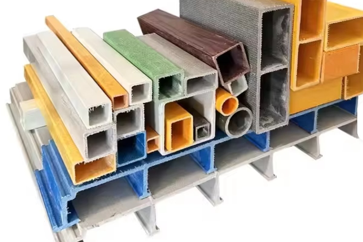
Done properly, an FRP racking system removes an entire maintenance category from a coastal or chemical plant: no repainting, no rust treatment at fixings, no annual coating condition survey. Done on steel assumptions, it removes nothing and adds a deflection problem. The difference is entirely in the load basis, the code, and the connections — which is exactly what this guide has tried to pin down. Our pultruded gel coat FRP square tube profiles, pultruded FRP I-beams and H-beams and pultruded FRP angle profiles are produced in E-glass with polyester or vinyl ester resin for outdoor load-bearing service, and we supply section properties, resin and fire documentation with the quotation. For the wider design context, see the pultruded profiles application guide, the bolted connection design guide, the custom pultrusion tooling guide and the comparison of FRP with wood and aluminium for outdoor structures.
Need help selecting FRP products?
Our engineers answer technical questions free of charge.
Ask an Engineer on WhatsApp