
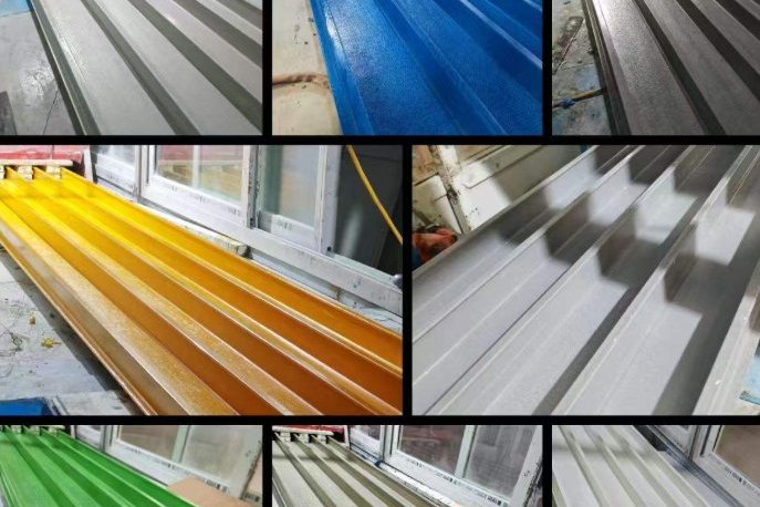
A rooftop is the one place where an FRP walkway has to fight gravity in both directions. Downward it carries maintenance workers, tools and snow; upward the wind peels at every panel edge and corner, and on the roof the suction peaks are two to four times what the interior field sees. Add a fragile membrane underneath, thermal movement from −20 °C mornings to 60 °C surface temperatures, and the safety obligation to provide safe access wherever the roof is walked regularly, and the walkway becomes a small structural system of its own: deck, clips, supports and substrate all sized against different loads. This guide works through each layer with the governing standards and worked numbers, from EN 1991-1-1 Category H loads to ASCE 7-22 corner-zone clip demands and pultruded grating span tables.
1. The Roof Is a Different Structural Duty
An industrial platform inside a plant and a walkway on a roof may use the same grating panel, but they answer to different rule sets. Roofs are categorised separately in the Eurocodes precisely because their duty is intermittent and weather-coupled. Three practical differences drive the design:
- Access is an obligation, not an option. Under the UK CDM Regulations 2015 and equivalent workplace safety law elsewhere, a roof that needs regular maintenance access must be provided with a safe, clearly demarcated walking route — which is exactly what a fixed walkway supplies, protecting both the worker and the roof covering from boot traffic.
- Wind acts on the walkway as an attached component. Panels and clips see the same corner vortices that damage roof coverings, so they are designed as components and cladding (C&C), not with the gentler averaged loads used for the main structure.
- Self-weight is a rounding error, not a stabiliser. A pultruded grating deck weighs 12–19 kg/m². Against roof suction pressures of 4–8 kPa, the deck's own weight is 2–4% of the uplift — every panel must be mechanically held down.
Those three differences — an imposed safety duty, an uplift-dominated load case, and a near-weightless deck — explain most of what follows.
2. The Governing Gravity Loads: EN 1991-1-1 Category H and ASCE 7
EN 1991-1-1 places roofs that are not accessible except for normal maintenance and repair in Category H. The recommended characteristic values are deceptively small: qk = 0.4 kN/m² uniformly distributed and Qk = 1.0 kN concentrated, with national annexes free to adjust them. The UK National Annex takes 0.6 kN/m² and 0.9 kN, France 0.8/1.5, the Netherlands 1.0/1.5, Germany 1.0 kN concentrated. Three clauses matter as much as the numbers:
- Category H loads are not combined with snow or wind. The imposed loads apply for the maintenance scenario on their own; where snow or wind governs the roof structure, the walkway connections still see the wind case of Section 3.
- The concentrated and distributed loads are verified separately, each on its own, not factored together.
- Roofs other than profiled sheeting must resist 1.5 kN on a 50 mm square — a deliberate provision for point features such as walkway feet and brackets pressing on a small contact patch.
| Load case | Value | Source | Notes |
|---|---|---|---|
| UDL, maintenance access | 0.4 kN/m² (recommended); UK NA 0.6; FR 0.8; NL 1.0 | EN 1991-1-1 Table 6.10, Cat. H | Not combined with snow/wind |
| Concentrated load | 1.0 kN (recommended); UK NA 0.9; FR/BE/NL 1.5 | EN 1991-1-1 Table 6.10 | Verified separately from UDL |
| Point feature on roof | 1.5 kN on 50 mm × 50 mm | EN 1991-1-1 §6.3.4.2 | Governs bracket bearing on soft insulation |
| Roof live load (US practice) | 20 psf ≈ 0.96 kN/m² | ASCE 7 ordinary flat roofs | Comparable duty to Cat. H |
| Prefabricated roof walkway test | 1.5 kN over 100 mm square, deflection ≤ min(15 mm, span/100), then 2.6 kN for 1 min | BS EN 516:2006 | Applies to proprietary walkway installations; min. width 250 mm |
The EN 516 test is worth quoting in specifications for proprietary walkway systems: it is a product-level acceptance test with a deflection criterion, not just a load rating, and any system claiming EN 516 compliance should come with test documentation for both the 1.5 kN and 2.6 kN stages.
3. Wind Uplift: C&C Zones on a Flat Roof
Wind does not lift a roof evenly. Flow separates at the corners and eaves and rolls into conical vortices, so the suction under those spirals dwarfs the interior field value. ASCE 7-22 handles this for small components with the C&C pressure coefficients of Figure 30.3-2A (flat roofs, h ≤ 60 ft):
| Roof zone | GCp @ 10 ft² effective area | GCp @ 500 ft² | Relative severity |
|---|---|---|---|
| Zone 1 — interior field | −1.7 | −1.0 | Baseline |
| Zone 2 — edge band | −2.3 | −1.4 | 1.35× Zone 1 (10 ft²) |
| Zone 3 — corners | −3.2 | −1.4 | 1.9× Zone 1 (10 ft²) |
The net design pressure is p = qh(GCp − GCpi), with the enclosed-building internal coefficient ±0.18 and qh the velocity pressure at mean roof height (Kd = 0.85 for buildings). The zone width a — the edge and corner band — is the lesser of 10% of the least horizontal dimension or 0.4h, but never less than the greater of 4% of that dimension or 3 ft (0.9 m). For a 30 m × 20 m building with a 9.1 m eave, that gives a = 2.0 m, which means every walkway that runs along a parapet or terminates near a corner passes through Zone 2 and Zone 3 territory.
Walkway runs along roof perimeters are the worst-case layout by construction: the same parapet the maintenance route serves is also where the edge and corner vortices park. If the route can pass 2–3 m inside the edge, every clip drops into Zone 1 pricing.
EN 1991-1-4 reaches the same physics through its roof pressure zones for local and overall cladding; the design habit is identical — zone the roof first, then design fixings zone by zone.
4. From Uplift Pressure to Clip Demand
Work the numbers for a realistic example: V = 150 mph (3-s gust), Exposure C, mean roof height 30 ft, enclosed building. The velocity pressure is qh = 0.00256 × 0.98 × 1.0 × 0.85 × 1.0 × 150² = 48.0 psf = 2.30 kPa. Applying the zone coefficients with GCpi = +0.18 (suction worst case):
| Zone | Net design uplift (strength level) | psf |
|---|---|---|
| Zone 1 — interior | 2.30 × (1.7 + 0.18) = 4.32 kPa | 90.2 |
| Zone 2 — edge | 2.30 × (2.3 + 0.18) = 5.70 kPa | 119.0 |
| Zone 3 — corner | 2.30 × (3.2 + 0.18) = 7.76 kPa | 162.2 |
Now divide that pressure among the clips. A 600 mm wide walkway panel with clips at s mm centres along both edges gives each clip a tributary area of 0.6 × s. Table 4.1 is the resulting demand per clip at strength level, with an ASD column at 0.6W (the usual factor pair for uplift with 0.6D):
| Clip spacing (mm) | Tributary (m²) | Zone 1 (kN) | Zone 2 (kN) | Zone 3 (kN) | Zone 3, ASD 0.6W (kN) |
|---|---|---|---|---|---|
| 400 | 0.24 | 1.04 | 1.37 | 1.86 | 1.12 |
| 600 | 0.36 | 1.55 | 2.05 | 2.80 | 1.68 |
| 800 | 0.48 | 2.07 | 2.73 | 3.73 | 2.24 |
| 1000 | 0.60 | 2.59 | 3.42 | 4.66 | 2.80 |
Two specification habits follow directly. First, clip spacing is a zoning decision: 600 mm centres may be fine in the field and demonstrably inadequate at corners, so a single "clips at 600 mm" line in a spec is an under-design at the corners. Second, the demand numbers here are the input to a fastener pull-out or clamp capacity test on the actual substrate — walkway clips, membrane-safe clamps and purlin screws have wildly different capacities, and none of them should be assumed without the manufacturer's tested value for the substrate in question.
5. Dead Load and Why It Barely Helps Hold the Deck Down
The numbers kill a comfortable assumption. A 38 mm pultruded I-bar grating at 73% open area weighs roughly 18 kg/m² — 0.177 kPa. Against even the mildest Zone 1 uplift of 4.32 kPa, self-weight is 24 times smaller. In the ASD uplift combination 0.6D + 0.6W, the dead-load credit on a 0.36 m² tributary is 0.6 × 0.177 × 0.36 ≈ 0.04 kN against a 1.68 kN clip demand — a 2% discount.
What self-weight does matter for: handling (a 3 m × 1 m panel at ~55 kg is a two-person lift), live-load deflection of the grating itself (Section 6), and the permanent load added to the building's roof structure, which is genuinely trivial — a 60 m run of 600 mm walkway adds about 650 kg to a roof that regularly carries plant units measured in tonnes. Design the deck for people, hold it down for wind, and never count one against the other.
6. Support Spans and Deflection: Reading Pultruded Grating Span Tables
Pultruded grating is strongly unidirectional — the I or T bars carry the load, the cross rods only keep them in line — so span tables apply in the bar direction only, and any cross-direction run needs its own support. Reputable manufacturers publish allowable uniform loads at deflection limit L/200 (with a maximum span stated). Typical published values for 38 mm I-bar pultruded grating, 30 mm bar pitch, read like this:
| Bar depth | SWL @ 600 mm span | SWL @ 900 mm | SWL @ 1200 mm | SWL @ 1500 mm | Weight |
|---|---|---|---|---|---|
| 25 mm I-bar | 6.5 kN/m² | 3.0 kN/m² | 1.8 kN/m² | 1.2 kN/m² | 15.5 kg/m² |
| 38 mm I-bar | 15.0 kN/m² | 7.0 kN/m² | 4.0 kN/m² | 2.6 kN/m² | 18.0 kg/m² |
| 50 mm I-bar | 28.0 kN/m² | 13.0 kN/m² | 7.5 kN/m² | 5.0 kN/m² | 22.0 kg/m² |
These ratings compress a lot of assumptions, so sanity-check the governing case yourself. For Category H the concentrated 1.0 kN is usually the design case, not the 0.4 kPa UDL. Treat the panel as a 1 m wide strip carrying the full 1 kN at midspan (conservative — no load distribution across bars), with the section properties of a typical 38 mm, 73%-open pultruded grating (I = 3.38 × 10⁵ mm⁴/m, S = 1.78 × 10⁴ mm³/m) and E = 23 GPa:
| Span L (mm) | Point-load deflection (mm) | Limit L/200 (mm) | Deflection check | Bending stress PL/4S (MPa) |
|---|---|---|---|---|
| 1000 | 2.68 | 5.0 | OK | 14.0 |
| 1200 | 4.63 | 6.0 | OK | 16.9 |
| 1500 | 9.04 | 7.5 | FAIL | 21.1 |
| 1800 | 15.63 | 9.0 | FAIL | 25.3 |
The bare-strip method says a 38 mm grating carries the 1.0 kN point load to about a 1.4 m span at L/200 — which matches manufacturer practice, since real panels distribute the point load across several bars and the published SWL at 1200 mm span (4.0 kN/m² UDL equivalent) comfortably covers a walking worker. The lesson is not that the tables are wrong; it is that a rooftop walkway rated for a lone worker needs roughly 1.0–1.2 m support centres in 38 mm material, and deeper bars or closer bearers where trolleys or stacked materials share the route. Also note the 0.4 kPa UDL produces under 0.1 mm of deflection at these spans — the point load is everything in Category H.
7. Mesh, Openings and Ball-Proofing Choices
Open area is a feature — it sheds rain, stops puddles and lets light through — but on a roof it interacts with what is underneath. The selection logic in ascending order of closure:
- Standard pultruded walkway mesh (60–73% open, ~30 mm pitch): the default for routes over robust coverings. Boots, drains and light all pass; a dropped spanner does not. Fine over concrete decks and protected plant zones.
- Reduced-aperture mesh: where the walkway crosses rooflights, fragile panels or accessible plant, smaller apertures limit what can drop through and spread the foot load over more bars.
- Ball-proof grating (12 mm sphere cannot pass): mandatory practice where a falling object could injure someone below — plant rooms over occupied space, walkways crossing above exposed services. It costs open area and weight, so apply it to the segments that need it rather than the whole run.
Whatever the mesh, the surface needs integral grit or applied grit for wet-weather grip; smooth-topped panel is a slip incident waiting for the first rain. On routes with a fall risk at the perimeter, pair the walkway with an FRP handrail system rather than relying on the walkway alone.
8. Fixings: Clips, Fasteners and the Uplift Load Path
The clip is the weakest physical link in the uplift chain, and the industry's standard answer is a small family of stainless hardware, each with a distinct job:
| Clip type | Mechanism | Best use |
|---|---|---|
| M (saddle) clip | Clamps two adjacent load bars to the support with a through bolt | Default choice — best holding capacity for pultruded grating |
| G clip | Lower jaw grips the support flange — no drilling of the support | Existing steelwork, hollow sections, any substrate you cannot drill |
| W clip | 40 mm recessed centre, fastener sits flush | Walkways where flush fixing matters (trolley routes, ADA-style decks) |
| PP clip | Fixes from below the panel | Visible-surface runs where no top-side hardware is wanted |
Standard practice: 316 stainless at the coast and in aggressive plants, 304 elsewhere; a minimum of four clips per standard panel; and materially more clips in Zone 2 and Zone 3 per the demand table in Section 4. Bolts are installed snug-tight — crushing a pultruded bar with an impact wrench is its own failure mode — and the support-side fixing (self-drilling screw into a purlin, clamp onto a standing seam, anchor into concrete) must be rated for the same uplift force, which for corner zones means tested pull-out or clamp capacities, not catalogue guesses. The clean way to close the loop is a simple pull test on site: install three clips and pull one to the ASD demand with a calibrated jack before the run is signed off.
9. Substrate Interface: Membrane, Standing Seam and Thermal Movement
On membrane roofs the walkway does double duty protecting the waterproofing, which means the fixing philosophy is to penetrate as little as possible. Options in order of invasiveness: paving-slab or pedestal ballast with no fixing (adequate where gravity exceeds uplift — but Section 5 showed grating alone never does), adhesive fixing pads, and through-fixing into the structural deck with a sealed, load-spreading plate per Section 2's 1.5 kN / 50 mm point provision. On standing seam and metal roofs, non-penetrating seam clamps carry the walkway supports, keeping the covering's warranty intact; the clamp capacity again needs manufacturer test data against the uplift demand.
Thermal movement is small but not zero, and pultruded FRP moves differently along and across the pultrusion axis. With a lengthwise expansion coefficient of roughly 9 × 10⁻⁶/K (below steel's 12 × 10⁻⁶) and a crosswise value several times higher, a 3 m panel crossing a 60 K surface-temperature swing moves about 1.6 mm along the run and, conservatively, 4–5 mm across it:
| Panel length | ΔT | Longitudinal ΔL (α ≈ 9 × 10⁻⁶/K) | Transverse ΔL (typ. ≈ 24 × 10⁻⁶/K, confirm with manufacturer) |
|---|---|---|---|
| 2000 mm | 60 K | 1.08 mm | 2.88 mm |
| 3000 mm | 60 K | 1.62 mm | 4.32 mm |
Detail a gap of about 8 mm at panel butts and clip clearances that do not lock the panel to the support in both directions — a walkway should not become a strut between two sides of a building at different temperatures. Confirm the actual expansion values with your supplier's datasheet, since they vary with fibre architecture.
10. Specification and Installation Checklist
A rooftop FRP walkway that survives its first winter storm was specified line by line. The items below close every loophole this article has opened:
- Zone the roof before fixing layout: mark Zone 1/2/3 bands on the walkway drawing and set clip spacing per zone, not one number for the whole run.
- State both load cases: Category H gravity (qk, Qk per the governing national annex) and C&C uplift per ASCE 7-22 or EN 1991-1-4 with the site wind speed.
- Require tested capacities: clip-to-panel and fastener-to-substrate, for the actual support member and coating, at the ASD demand of the governing zone.
- Set the span table: bar depth, bar pitch, support centres, deflection limit L/200, and the point-load case (1.0 kN) as the governing check.
- Specify mesh and surface: open area, reduced aperture or ball-proof segments where required, gritted surface throughout.
- Protect the covering: non-penetrating clamps on metal roofs, sealed load-spreading plates on membranes, EN 516 test certificates for proprietary systems.
- Detail the movement: 8 mm butt gaps, no two-directional locking, expansion values from the supplier datasheet.
- Site-verify: snug-tight torque only, pull test on three clips per run, and a final check that no clip spacing in the corners drifted during installation.
Done this way, an FRP rooftop walkway is a 25-year asset: light enough to install without cranes, inert under UV and weathering with a proper surface veil, non-conductive around rooftop electrics, and — because the clips were zoned and tested — still where you left it after the storm that rearranged the loose sheet metal.
Plan Your Rooftop Walkway With Us
Send us the roof plan with your wind zone, support layout and access route. We will return the panel selection, span table, per-zone clip schedule and fixing details — normally within one working day.
Related reading: FRP Grating Load Tables: Reading Uniform and Concentrated Loads · Pultruded FRP Solar Mounting Structures: Wind Uplift on Roofs · FRP Grating Fabrication and Installation: Field Cutting and Clip Fixing · FRP Grating and Handrail Condition Assessment · Product pages: Pultruded hollow FRP walkway grating panel · FRP grating, walkways and stair treads · FRP handrail profiles for walkway edges
Need help selecting FRP products?
Our engineers answer technical questions free of charge.
Ask an Engineer on WhatsApp