
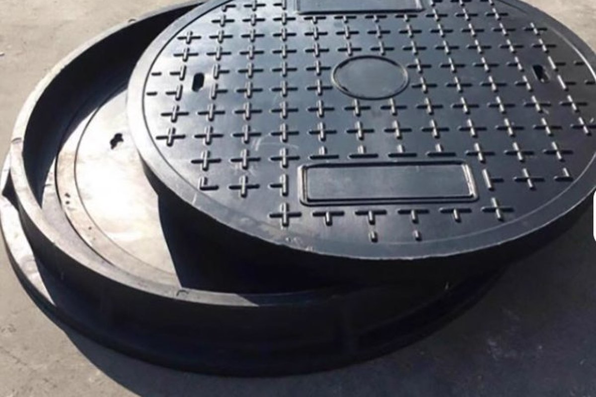
An SMC cover or enclosure is usually bought as a catalogue item and specified in one line: "500 × 500, grey, load class D400". That single line hides a process with about a dozen variables that decide whether the part arrives flat, dense and dimensionally stable, or arrives with porosity under the gel coat, a warp that will not sit on its frame, and a knit line exactly where the gasket has to seal. The part is not made by a machine; it is made by a compound state, a charge pattern and a thermal cycle that have to agree with each other.
This guide treats compression moulding as a process-control problem rather than a materials lecture. Every threshold below is either taken from a published standard or from the shop-floor ranges that compounders and press builders publish, and every number that is derived is calculated in a script so it can be checked. Anchors for the hardware are the SMC anti-slip access cover for sewage inspection, the SMC manhole cover with printable logo and the SMC moulded septic tank.
1. What Compression Moulding Does to the Compound
In hand lay-up the resin is liquid, the reinforcement is placed where the laminator puts it, and the part cures with almost no flow. In compression moulding the compound arrives as a semi-solid sheet or a dough, is cut into a charge, and then has to flow across the cavity while it heats, gels and cures. That flow is the source of both the process's advantage and most of its defects: it closes complex geometry in one shot, but it also drags fibre, creates weld lines and traps gas.
The three compound families behave differently because their fibre length and fibre content differ, not because the resin is different.
| Property | SMC (sheet) | BMC / DMC (bulk / dough) | Consequence in the press |
|---|---|---|---|
| Chopped fibre length | Typically 25–50 mm | Typically 6–12 mm | Longer fibre gives higher strength and impact, but restricts flow into thin ribs |
| Reinforcement content | 15–70 % by mass per ISO 8605 | 10–35 % by mass typical | Above roughly 55 % glass, flow length collapses and the part must be simple |
| Form supplied | Sheet between carrier films, 1–25 mm thick | Extruded logs or slugs | SMC is cut and stacked; BMC is weighed and dropped, so charge weight control differs |
| Typical parts | Large flat or gently curved covers, panels, enclosures | Small complex housings, inserts, electrical boxes | Choose BMC when geometry, not area, is the difficulty |
The practical point is that a 30 % glass SMC and a 30 % glass BMC are not interchangeable even at the same density. The SMC will bridge a 60 mm deep rib with fibre continuity; the BMC will fill the rib but with much shorter fibre, so the rib root becomes the weak section. If a drawing has deep ribs, small bosses and tight radii, the compound choice is already made by the geometry.
2. Reading the Compound Specification Before Reading the Price
"SMC" is a form, not a grade. Two suppliers can both quote 30 % glass, 1.9 g/cm³ and 60 MPa flexural strength and still deliver materials that behave completely differently in a 150 °C mould, because glass length, filler loading, low-profile additive and thickener dosage are not in that headline.
The current material standards give a proper vocabulary. ISO 8605:2024, the third edition published in March 2024, covers SMC reinforced with glass or carbon fibre, defines a designation system and classifies compounds by shrinkage behaviour; its general-purpose class is defined as 0.2–0.5 % cure shrinkage. ISO 8606:2025 does the same job for BMC and DMC and adds a four-level shrinkage scale: S1 at nominally zero, S2 below 0.05 %, S3 from 0.05 % to 0.2 % and S4 from 0.2 % to 0.5 %. In Europe, EN 14598-2 and EN 14598-3 set out test methods and specific requirements, and EN 12576 governs how the compression-moulded test plate itself is made.
| What the purchase order should state | Why it changes the part | Typical value to expect |
|---|---|---|
| Resin family (UP, VE, EP, phenolic) | Sets chemical resistance, heat distortion and fire behaviour | Isophthalic UP for general covers; vinyl ester for sewer gas and chemical duty |
| Reinforcement type, length and mass fraction | Controls strength, impact and how far the charge can flow | 25 mm chopped roving, 25–35 % for structural covers |
| Shrinkage class | Controls warp, sink and mould compensation | S3 (0.05–0.2 %) for general covers; S1/S2 for visible Class A faces |
| Filler type and loading | Calcium carbonate adds stiffness and cuts cost; ATH adds fire performance and releases water above about 220 °C | CaCO3 120–200 phr; ATH 80–150 phr for flame-retardant grades |
| Low-profile additive (LPA) | Compensates polymerisation shrinkage; too little gives sink, too much gives flow problems | 15–25 phr of a thermoplastic LPA |
| Initiator system | Sets the temperature at which the compound gels in the mould | TBPB or TBPO at roughly 1–2 phr |
| Thickener (MgO or Mg(OH)2) | Creates the maturation curve that makes the sheet handleable | 1–3 phr, adjusted to resin acid value |
| Internal release agent | Controls sticking and surface finish | Zinc stearate 2–4 phr |
| Shelf life and storage temperature | A batch outside its window is a different material | Typically 15–25 °C storage; weeks, not months, at ambient |
Note what is missing from that table: a single viscosity number. Compound viscosity is not a material constant, it is a point on a curve that moves with time and temperature. That is the subject of the next section, and it is where most incoming inspection fails.
3. Maturation Is a Process Variable, Not a Warehouse Delay
SMC is not ready when it is made. Magnesium oxide reacts with the carboxylic acid end groups of the unsaturated polyester and builds an ionic network, which turns a 30–50 Pa·s paste into a sheet that can be handled, cut and stacked without flowing off the film. The reaction takes 24–72 hours at 25–35 °C, and the sheet passes through a window in which it flows well enough to fill the cavity but not so well that it washes fibre out of the charge.
The mistake is to treat maturation as a fixed number of days printed on the box. Two batches with the same formulation can mature at different rates because MgO particle size, acid value and plant temperature all move the curve. ISO 12115:1997 exists precisely for this: Method I presses a specimen at 23 ± 2 °C under one of three loads (390 N, 1,000 N or 2,000 N) and records how far the punch sinks in 45 seconds, with a target sink of 30–70 % of specimen thickness; Method II repeats the test in a heated shear-edge mould under production-like closing speed and pressure. Three specimens are required, and the result is a maturation curve, not a pass/fail slip.
A compound that is 24 hours past its usable window is a different material, even though the batch number, the colour and the certificate have not changed. Purchasing a viscosity number instead of a curve is how a good formulation becomes a short shot.
At the press, the symptoms are easy to read, and they point in opposite directions:
- Under-matured compound flows too freely. Resin runs to the edges, fibre is pushed to the perimeter, knit lines are weak, and flash sets before the cavity is full.
- Over-matured compound does not flow at all. Short shots appear at the far end of deep ribs, boss tops stay unfilled, and the press reaches tonnage before the cavity is full.
- Correctly matured compound fills the cavity at 50–70 % charge coverage, produces a continuous flash ring and releases with a uniform matt surface.
In the first two cases the operator's instinct is to change pressure or temperature. Neither fixes a maturation error, and both make the record harder to interpret afterwards.
4. Charge Pattern: Weight, Coverage and Placement
The charge is a mould tool in its own right. Its weight sets part density and flash; its area sets flow distance; its position sets where the flow fronts meet. Get the weight right and the coverage wrong and the part will still short-shot at the far corner.
Weight follows directly from part volume and compound density. For a 500 × 500 × 4 mm cover at 1.90 g/cm³, the volume is 1.00 litre and the part mass is 1.90 kg; with a 5–12 % allowance for flash, runners and weight variation, the cut charge is 2.00–2.13 kg. That allowance is not a safety factor for bad weighing; it is the difference between a full cavity and a trim press full of flash.
Coverage is the more interesting variable. Published shop-floor ranges converge on 50–70 % of the projected cavity area, with lower coverage used for large simple panels and higher coverage for complex parts. The reason is flow ratio: the distance the compound must travel divided by the part thickness. The table below calculates the corner flow distance for a centred square charge in a 500 mm square cavity.
| Charge coverage | Equivalent square charge | Flow to farthest corner | Flow ratio at 4 mm wall | Flow ratio at 3 mm wall |
|---|---|---|---|---|
| 40 % | 316 mm | 130 mm | 32.5 : 1 | 43.3 : 1 |
| 50 % | 354 mm | 104 mm | 25.9 : 1 | 34.5 : 1 |
| 60 % | 387 mm | 80 mm | 19.9 : 1 | 26.6 : 1 |
| 70 % | 418 mm | 58 mm | 14.4 : 1 | 19.2 : 1 |
As a working rule, keep the flow ratio below about 50 : 1 for random SMC. Above that, fibre and resin separate, the far edge becomes resin-rich or starved depending on the temperature profile, and the knit line where the two flow fronts meet has almost no strength. A 3 mm wall at 40 % coverage is already at 43 : 1, which is why thin large covers are usually run at 60–70 % coverage or with a thicker wall at the gate.
Placement matters as much as area. Put the charge symmetrically for a symmetrical part; offset it towards the deepest ribs when one side is deeper; never stack a charge directly on a delicate insert; and keep the final knit line away from sealing faces, bolt holes and any area that will be machined. If the knit line cannot be moved, it must be recorded on the drawing as a controlled feature, because a gasket that crosses a weld line will leak at the first thermal cycle.
5. Mould Temperature and the Cure Window
For unsaturated polyester SMC the useful mould temperature band is roughly 140–160 °C, with upper and lower platens held within about 5 K of each other and each zone controlled to about ±2 K. Below that band the compound gels too slowly, styrene is lost and the surface stays tacky; above it the surface cures before the core, and the part leaves the tool with a hard skin over an under-cured centre.
Thick parts need a lower set point, not a longer cycle alone. A 25–32 mm section is commonly run at 135–145 °C because the exotherm in the core adds to the platen temperature, while thin sections can be run hotter. The cure time itself scales with thickness, and the 30–60 s/mm band published by compounders and press builders is a reliable starting point.
| Wall thickness | Cure time at 30 s/mm | Cure time at 60 s/mm | Practical cycle |
|---|---|---|---|
| 3 mm | 90 s | 180 s | 1.5–3.0 min |
| 4 mm | 120 s | 240 s | 2.0–4.0 min |
| 6 mm | 180 s | 360 s | 3.0–6.0 min |
| 10 mm | 300 s | 600 s | 5.0–10.0 min |
Cure is verified by hardness, not by clock. Barcol hardness on a moulded SMC surface typically runs 40–50 for polyester systems, and the acceptance floor should be set against a baseline moulded from the same compound, not against a generic number. A part that reads 10 points below its own baseline is under-cured even if it looks perfect, and it will continue to shrink and warp after machining. Barcol readings are only comparable within one resin family; using them to compare a polyester with a vinyl ester is meaningless.
6. Pressure, Clamping Force and Venting
Moulding pressure for SMC is usually quoted at 5–15 MPa on the projected area, with the higher end for complex geometry, high fibre content and well-matured compound. That number has to be converted into press tonnage before a quotation is credible, because the press is sized on force, not on pressure.
| Projected area (500 × 500 mm part) | At 5 MPa | At 8 MPa | At 12 MPa |
|---|---|---|---|
| Part only, 0.250 m² | 1,250 kN (127 tf) | 2,000 kN (204 tf) | 3,000 kN (306 tf) |
| Part + 15 % runner and flash, 0.288 m² | 1,438 kN (147 tf) | 2,300 kN (235 tf) | 3,450 kN (352 tf) |
A 500 mm cover therefore needs a 250–350 tonne press at the top of the pressure range, and a 400 tonne press is not excessive once the margin for off-centre loading and pressure fluctuation is added. Quoting a 200 tonne press for that part means either the pressure is too low or the projected area has been underestimated, and both show up later as porosity or short shots.
Pressure does not remove gas; venting does. The closing sequence should be two-stage: fast approach to within a few millimetres, then a controlled slow closing at roughly 1–3 mm/s, with a dwell of 3–5 seconds at about 90 % closure to let the cavity breathe before full tonnage. For Class A surfaces, thick sections or parts with deep ribs, vacuum assistance is more effective than another 2 MPa of pressure. Vent slots of 0.05–0.1 mm at the last points to fill, plus a vacuum connection, will do more for porosity than any change in the resin formulation.
If a part is porous, the first question is not "what pressure are we running?" but "where does the gas come from, and where can it leave?" Pressure compresses gas; it does not delete it.
7. Porosity: Identify the Gas Before Changing the Recipe
Porosity in SMC has four possible sources, and they look similar in a cross-section but behave differently in the press. The diagnostic value comes from position and timing.
| Signature | Most likely gas source | Confirming check | Corrective action |
|---|---|---|---|
| Fine scattered pores over the whole surface, worse at the far edge | Air entrained during compounding or charge handling | Density below the compound certificate; pores round and isolated | Vacuum assist, slower final closure, vent at last-fill point |
| Blisters that appear only after demoulding, sometimes hours later | Moisture from roving, filler or humid storage | Weight loss on drying; water absorption test on a moulded plate | Dry filler and roving; store sheet sealed at 15–25 °C; check ATH grade |
| Large voids at rib roots and thick-to-thin transitions | Styrene vapour or air trapped by premature skin cure | Void surfaces glossy and resin-rich; short shot nearby | Lower the temperature ramp, increase charge coverage, vent the rib |
| Pinholes in a band across the part | Volatiles from filler or from too much release agent | Band corresponds to a charge edge or a vent location | Reduce zinc stearate, change filler lot, move the vent |
The scale of the moisture problem is worth calculating. At 150 °C, 0.2 % water by mass in the compound produces about 3.9 litres of steam per kilogram of compound at atmospheric pressure, or 0.8 litres at 5 bar cavity pressure. That is not a trace; it is a bubble large enough to destroy a gel coat. At 0.5 % water the volume rises to 9.8 litres per kilogram at 1 bar. A bag of filler left open over a humid weekend is therefore a process change, not a storage detail.
Verification should include density to ISO 1183 against the theoretical value from the formulation, water absorption to ISO 62 on a moulded specimen, and a polished cross-section under low magnification. Density alone will miss a thin skin of surface porosity; the section will show whether the pores are round (gas) or elongated along the flow direction (fibre separation).
8. Warpage and Sink: Shrinkage Is a Design Input
Every moulded part leaves the tool smaller than the cavity and then continues to move as it cools. The two effects are additive and both are predictable.
| Effect | Assumption | Movement over 500 mm |
|---|---|---|
| Mould shrinkage, general purpose | 0.50 % | 2.50 mm |
| Mould shrinkage, low shrink | 0.05 % | 0.25 mm |
| Mould shrinkage, low profile | 0.02 % | 0.10 mm |
| Cooling from 150 °C to 23 °C | α = 25 µm/m·K, ΔT = 127 K | 1.59 mm |
| Combined, 0.30 % shrink plus cooling | ΔT = 127 K | 3.09 mm |
A 3 mm total movement on a 500 mm cover is enough to lift a corner off its frame, which is why mould dimensions are compensated rather than cut to the drawing. The mould maker needs the shrinkage class before he starts, not after the first article. It also explains why changing from a general-purpose to a low-profile compound mid-project is a tooling change, not a material substitution: the same cavity will produce a part 2.4 mm larger in each dimension.
Warp has separate causes from uniform shrinkage, and they are worth separating before the tool is modified:
- Thermal asymmetry. A platen difference of 10–15 K cures one face before the other, and the part bows towards the cooler face.
- Fibre asymmetry. A charge placed off-centre, or a ribbed underside against a flat top, produces different shrinkage on the two faces.
- Uneven ejection. Ejector pins that act on one side first bend the part while it is still soft.
- Early demoulding. A part pulled while the core is above its heat distortion temperature will creep under its own weight on the rack.
Post-curing at 80–120 °C for 1–3 hours relieves residual stress and is reported to reduce warpage substantially, but it cannot straighten a part that was moulded with a 15 K platen difference. Fix the thermal symmetry first, then post-cure.
9. Inserts, Ribs and Thick-to-Thin Transitions
The defects that reach the customer are rarely in the flat panel. They are at the features: a boss that cracks at the root, an insert that pulls out, a rib that shows a sink mark on the visible face, or a step where a 10 mm section meets a 3 mm section and the thick side pulls the thin side into a bow.
- Bosses and inserts. Metal inserts have a different thermal expansion from the compound and act as heat sinks in the mould. Preheat them to within about 20 K of the mould temperature, knurl or undercut the outside, and keep at least one wall thickness of compound around the insert. A cold insert produces a resin-rich, porous ring that will crack on the first torque cycle.
- Rib proportions. Keep rib thickness at 0.6–0.8 of the adjacent wall and put a fillet of at least 0.5 mm at the root. A rib as thick as the wall will sink on the opposite face; a rib with a sharp root will crack when the part is ejected.
- Section transitions. Step from thick to thin over a length of at least three times the thickness difference, with a fillet at the change. An abrupt step creates a flow front that stalls, and the resulting void is invisible from outside.
- Draft and ejection. One degree of draft per side is a minimum for textured surfaces; 0.5 degree is workable on polished vertical walls. Ejection pins should act on bosses or thick sections, never on a thin cosmetic face.
These are design rules, not process fixes. Once the tool is cut, the press can only compensate at the margin, and compensating usually means slowing the cycle and accepting a higher scrap rate.
10. First-Article Acceptance and a Shop-Floor Checklist
The first article is the only point at which material, tool and process can be judged together, so the record should be complete enough to reproduce the part later. A useful first-article sheet for an SMC cover or enclosure contains the following.
| Check | Method or reference | Acceptance |
|---|---|---|
| Compound identity and batch | Supplier certificate plus retained sample | Resin, glass content, shrinkage class and shelf-life date match the order |
| Maturation record | ISO 12115 Method I maturation curve | Flow within the agreed band on the day of moulding |
| Charge weight and coverage | Scale and placement photograph | Within ±2 % of nominal; coverage as agreed |
| Mould temperature | Calibrated contact probe, four corners plus centre | Set point ±2 K; platen difference ≤5 K |
| Cure | Barcol hardness, ASTM D2583 or EN 59 | ≥90 % of the baseline for the same compound |
| Density and porosity | ISO 1183; polished cross-section | Within 2 % of theoretical; no connected porosity at sealing faces |
| Water absorption | ISO 62 on a moulded specimen | Within the compound specification |
| Flexural properties | ISO 14125 on specimens from the same plate | Meets the drawing or the material datasheet |
| Dimensions and flatness | Drawing; flat plate on a surface table | Within drawing tolerance; no rock over the sealing face |
| Load class, if applicable | EN 124-1 class test for covers | Class A15 to F900 as specified, including permanent set |
Two notes on that table. First, a certificate of conformity from the compound supplier is not a substitute for a retained sample: if a batch behaves differently three months later, the sample is the only evidence left. Second, the load class of a cover is a system property of cover plus frame, not of the cover alone. Testing a cover on a rigid steel platen and installing it in a flexible concrete frame is how a D400 product becomes a C250 installation.
Compression moulding rewards discipline more than it rewards capital. A 250 tonne press with a measured maturation curve, a weighed charge and a four-point temperature check will out-perform a 400 tonne press run on guesswork. The specification should ask for the records, not just the part.
For the adjacent processes, see FRP grating moulding machine operation for the mould-and-cycle side of a different product, molded versus pultruded grating for the process comparison, FRP manhole covers versus cast iron for the load-class argument, and FRP tank covers and odour-control hoods for the sealing and headspace chemistry that sits above these covers. The hardware range is here: SMC anti-slip access cover, SMC cover with printable logo, SMC septic tank and SMC moulded pipe fittings.
Need help selecting FRP products?
Our engineers answer technical questions free of charge.
Ask an Engineer on WhatsApp