
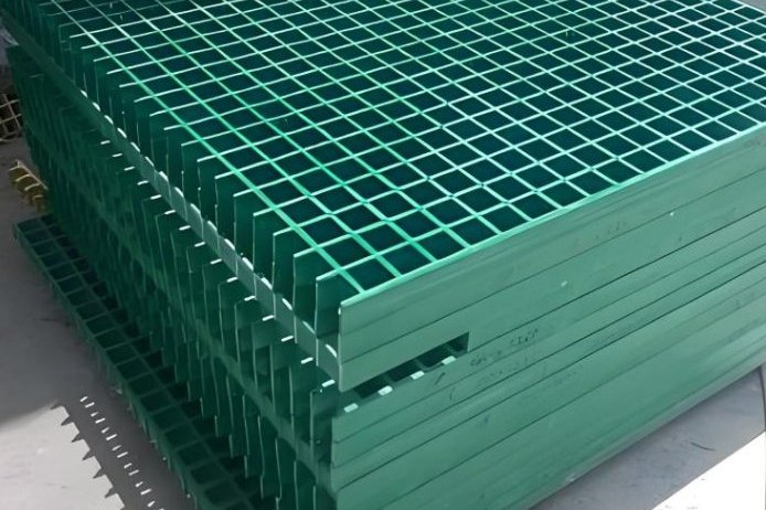
Walk into a cooling tower or a wastewater treatment plant and the one material decision that has already been made for you is the decking. FRP grating is the default not because it is fashionable but because the two environments are unusually hostile in a way that no metal survives cheaply: warm chlorinated water and continuous UV above, and hydrogen sulphide turning into sulphuric acid in the condensation below.
What is not already decided is how the grating is framed, fitted and maintained. Almost every failure we see in these plants traces back to support spacing, clip detailing, expansion allowance or a cut edge that was never sealed — not to the resin. This guide covers the framing and fitting rules that make the difference, and the inspection points worth checking on an FRP deck that has been in service for years.
1. Why FRP Grating Is the Default Material in These Two Plants
The case is documented and specific, not general.
- Hydrogen sulphide. Sulphate-reducing bacteria in septic and anaerobic zones generate H2S — municipal digesters routinely run at several hundred parts per million, with upset conditions going higher. The gas dissolves in condensation water on any cool surface and oxidises to sulphuric acid, dropping local pH to the region of 1–2. Carbon steel grating in that environment is reported to lose 0.1–1.0 mm of section per year and can reach structural failure within 3–5 years. Vinyl ester FRP is not attacked by H2S or by the biogenic acid it forms.
- Warm chlorinated water. Cooling tower decks sit above water that is typically 30–45 °C, dosed with oxidising biocide, and permanently wet. Hot-dip galvanising dissolves in that service; stainless steels pit under deposits where chlorides concentrate.
- UV. A tower deck is fully exposed, and it is the one FRP location where the surface has to be designed for decades of solar radiation rather than the occasional shaft of light. Gel coat quality and UV-stabilised resin matter as much as the structural grade.
- Drainage and weight. Open-area grating lets water and debris pass rather than pooling, and it is light enough to be handled without crane access on most retrofit jobs — an advantage that matters every time a panel has to be replaced.
On these decks the grating is usually the cheapest component in the access system and the one most often blamed. Support steel, clips and edge details decide how long a panel actually lasts.
2. Zone-by-Zone Service Conditions
Both plants are usually specified as one project, with one grating type, and that is a mistake. From a materials point of view these are different environments in different places about twenty metres apart.
| Location | Chemical environment | Temperature | Wetness / UV | Typical resin and grade |
|---|---|---|---|---|
| Cooling tower hot-water distribution deck and fan deck | Chlorinated or brominated water, drift, biocide, occasional scale inhibitor | 30–45 °C water; deck surface higher in sun | Permanently wet, full UV, freeze-thaw in cold climates | Isophthalic or vinyl ester moulded grating, grit or concave top; UV-stabilised |
| Cooling tower fan access and drive platform | Same as above, plus oil and grease from gearboxes | Ambient to 45 °C | Wet and oily, full UV | Vinyl ester moulded grating with grit surface |
| Aeration basin perimeter and centre walkways | Aerobic mixed liquor, minor acids and alkalis; heavy spray and mist | 10–35 °C | Permanently wet, full UV, biofilm on surfaces | Isophthalic or vinyl ester, water-resistant; grit recommended |
| Headworks, screen house, grit chambers | Raw sewage, grit, rag, variable industrial discharges | 10–30 °C | Wet with solids loading, humidity | Vinyl ester; higher depth for impact; consider mini-mesh where spill-through must be limited |
| Primary and secondary clarifier walkways | Sulphide-bearing sludge, algae on exposed decks | 10–35 °C | Wet, UV, algae growth | Vinyl ester; grit surface for slip resistance when algae film forms |
| Anaerobic digester dome and gas area | H2S, high humidity, gas-tightness requirements | 35–40 °C in enclosed zones | Condensation, low UV inside enclosures | Vinyl ester; phenolic where fire and smoke performance is required |
| Chlorination and dosing areas | Sodium hypochlorite, ferric chloride, lime dust | Ambient | Wet with chemical spills | Vinyl ester; verify concentration and temperature against the resin's resistance table |
Two practical observations follow. First, the resin decision is usually settled by the worst zone on the project, and the temptation is to downgrade the remaining 80% of the deck to save money — which then makes the whole plant's spares list two different products instead of one. Second, the top surface decision is independent of the resin: on a permanently wet deck, slip resistance and biofilm management matter more to a walking operator than the resin chemistry.
3. How the Load Gets From the Deck to the Structure
FRP grating carries load in one direction. The bearing bars — the continuous bars running the length of the panel — must run perpendicular to the support beams. Install a panel rotated 90°, and you have not built a 40% weaker deck, you have built a deck whose load capacity is a fraction of the design value and whose deflection is not covered by any load table. This single error accounts for a large share of "defective" grating complaints.
The framing rules that follow from it:
- Support spacing is the governing dimension. Grating load tables give a capacity for a given span and deflection limit; change the span and everything moves. A 500 mm span behaves completely differently from 1,200 mm, and the difference is not linear.
- Moulded and pultruded grating are not interchangeable at the same span. Moulded grating is bidirectional and well suited to short and medium spans; pultruded grating has unidirectional load-bearing bars and takes significantly longer spans at higher loads. Where a retrofit increases the gap between existing beams, the panel type usually has to change with it.
- Deflection limits control the design, not ultimate strength. Pedestrian decks are usually governed by L/200 or L/150, with L/100 used as the absolute outer limit for less sensitive areas. A deck that passes a strength check but bounces at L/80 is a deck nobody will keep using.
- Residual safety factor. Ageing, cut panels, UV exposure and unsealed edges all reduce capacity over time. Keeping a residual safety factor of around 2 on the design load is normal practice for access structures, and it is what allows an inspectable 15-year-old deck to still be signed off.
- Limit overhang. Panels should not cantilever beyond a support by more than about 150 mm (6 in). Overhanging ends are unsupported walking edges that crack, trip people and collect damage.
4. Support Beams, Clips and Fastener Torque
The support structure in these plants is normally pultruded FRP I-beam or wide-flange profile, bolted or clipped to the tank or basin wall. The grating is then clipped to the beams — never welded, and rarely bolted directly.
| Item | Typical practice | Why it matters |
|---|---|---|
| Clip type | M (saddle) clips hold the panel down to the beam; C (connection) clips align adjacent panels; L (edge) clips secure the boundary | Each solves a different failure mode. Using M clips only leaves panel-to-panel joints free to creep apart. |
| Clip material | 316 stainless for towers, WWTP and any chlorinated or acid-exposed location; 304 for benign indoor areas | Clip failure from chloride pitting is a real mechanism in these plants and takes the panel with it. |
| Number of clips | Minimum four per panel — one at each corner — with extra clips at edges, penetrations and high-traffic zones | Under-clipping is the most common installation defect: the panel moves, the load path becomes indeterminate and fasteners loosen. |
| Clip spacing along edges | Roughly 300–600 mm (12–24 in), tightened at midpoints as well as edges | Even load transfer and a panel that does not drum or rattle under foot traffic. |
| Bolt torque | Approximately 5–10 N·m, with a washer under the head | FRP crushes. Over-torquing starves the laminate under the clip and creates the crack that appears at year three. |
| Washers and isolation | Large-diameter washers; rubber or polymer washers where the clip bears on the panel | Distributes bearing pressure and reduces fretting between stainless and FRP. |
| Fasteners through the panel | Avoid. Use clips; where bolting through is unavoidable, plan holes at the design stage | Drilling a bearing bar at random cuts the load path and is a stress concentration. |
5. Thermal Movement: The Gaps Nobody Leaves
FRP expands more than steel: on the order of 1.0–2.5 × 10⁻⁵ per °C depending on the laminate, so a 6 m panel moving through a 40 K seasonal swing changes length by roughly 2.4–6 mm. In a cooling tower the deck may see an even wider surface swing in direct sun, and in a treatment plant the daily temperature range is smaller but the deck rarely sits still.
Expansion allowance: ΔL = L × α × ΔT, with α taken from the panel supplier's data for the actual laminate, not from a generic FRP figure. Leave 3–5 mm between panels and allow more at walls and fixed obstructions.
What happens if the gaps are omitted is not a graceful failure. Panels butt tightly, then push into each other and against the containment kerb. The result is a rising, ridged deck, clips that shear or pull out, fasteners that work loose, and local crushing of the panel edges. It shows up in the first hot spell after installation and is frequently reported as a product defect.
Practical detailing:
- Leave 3–5 mm between adjacent panels, and a clear gap at every wall, kerb and fixed obstruction so the deck can grow.
- Do not fill the gaps with mortar, mastic or any rigid material — the panel will simply load the obstruction instead.
- Detail C clips so panels can still slide marginally within the joint; over-tightened connection clips convert a moving joint into a stressed one.
- Where the deck runs several metres between fixed points, treat it as a designed expansion joint and record the location on the as-built drawing.
6. Cut-to-Fit Around Risers, Nozzles and Fan Decks
Almost no real deck is built from whole panels. Pipe risers, air laterals, fan drive columns, instrument stands, drain points and handrail posts all interrupt the layout, and every field cut is a place where the edge seal is lost.
- Diamond or carbide blade only. Cut dry or with water suppression and dust control; FRP dust is an inhalation hazard and needs extraction or respiratory protection.
- Never flame-cut, weld or grind FRP. There is no hot-work route on this material. That is an advantage on a live plant, but it means the layout has to be right before cutting.
- Seal every cut edge with two coats of resin matched to the panel resin. An unsealed cut edge exposes raw fibres, wicks water, and is the first place a panel delaminates or fails in a chloride environment.
- Support cut panels across a beam, not in mid-air. Keep at least one bearing bar on each side of the opening wherever the deck carries traffic, and frame the opening with pultruded profile rather than relying on the edges of neighbouring panels.
- Watch the load direction after cutting. Removing a section of panel can leave a strip whose bearing bars now span a longer distance than the design allows.
- Do not use the openings to route temporary services. Decks get overloaded by later modifications more often than by design traffic.
7. Access, Egress and Edge Protection
The deck is the walking surface of an access system, and the surrounding items are what make it usable and safe:
- Guardrails and handrails on every open edge, at the heights and loadings required by the governing code — with the caveat that these are project-specific and should be checked against the applicable standard, not copied from a previous job.
- Toe plates of about 100 mm minimum height around open edges, which in these plants serve a dual purpose: they stop dropped tools and they stop debris being pushed into the tower or the basin.
- Stair treads and nosings matched to the decking so that a change of surface does not coincide with a change of slip resistance underfoot.
- Clear width retained around drips, brackets and valve stems. A deck that is nominally a walkway but effectively 400 mm wide will be climbed over rather than used.
- Penetration labelling. In a plant where every opening looks identical from above, tagging the deck around risers and access holes prevents a future contractor from cutting the wrong one.
8. Slip Resistance on a Permanently Wet Deck
A dry friction coefficient tells you very little about how a deck behaves once it has carried a biofilm for two years. In cooling towers the top surface grows algae and scale; in treatment basins it grows biological slime. Both are more slippery than clean water.
- Grit surfaces earn their cost here. Quartz or aluminium oxide grit gives a friction level that survives an organic film far better than a plain or concave top surface. On inclined decks and stair treads, grit-coated is effectively mandatory.
- Wet and oily areas need the grit too, not just wet areas. Fan deck access platforms collect gearbox oil, which is worse than water by a wide margin.
- Cleaning is part of the specification. A grit deck that is never cleaned performs like a plain deck. Plan a cleaning interval into the maintenance schedule — pressure washing for the towers, and appropriate measures around the basin where run-off returns to the process.
- Replace panels that have lost their texture, not panels that have lost their colour. Surface erosion from hot, chlorinated water eventually exposes the glass pattern; that is the point at which the top surface stops doing its job.
9. What Actually Fails, and How to Find It
Across these two plant types, the same handful of failure modes repeat. Each has a low-cost inspection method and a defined trigger for action.
| Failure mode | Root cause | How to find it | Action |
|---|---|---|---|
| Exposed fibre / glass pattern on top surface | UV chalking and erosion of gel coat; hot chlorinated water | Visual walkdown in raking light; compare against a spare panel | Replace when the surface texture and grit are gone, or the glass is visible |
| Delamination at cut edges and around openings | Unsealed cut edges wicking water and chemicals | Press and tap-test edges; look for swelling and dark staining | Seal immediately if localised; replace if the edge has opened into the bearing bars |
| Loose or missing clips | Under-clipping, over-torqued or corroded fasteners, un-allowed expansion | Walk the deck and listen; check every clip at the joints during shutdown | Re-clip to specification; re-torque to 5–10 N·m |
| Visible sag between supports | Support spacing exceeded, or creep after long hot-wet exposure | Straight-edge and tape across the span; compare with the original layout drawing | Add an intermediate beam or replace with a deeper panel — do not simply re-clip |
| Ridges and buckled joints | No expansion allowance; panels butting hard against each other or a kerb | Look along the deck line in hot weather | Re-cut the joint and re-establish the gap; check clips for damage |
| Panel movement and noise under foot traffic | Insufficient clips, wrong load direction, or a panel trimmed too small | Step-test methodically across the panel and observe the joint | Re-clip all four corners minimum; verify bearing-bar orientation |
| Localised white deposits or blistering | Chemical attack beyond the resin's resistance envelope, or contamination from a spill | Visual and wipe test; check the actual chemical and temperature against the resin chart | Replace the affected panels with a higher-grade resin; investigate the source before re-installing the same grade |
| Cracking around handrail posts and penetration frames | Point loads and un-reinforced openings in an FRP deck | Visual around every post base and frame | Reinforce the opening with pultruded profile; replace the cracked panel |
10. Inspection Cadence, Records and Replacement Planning
An FRP deck does not degrade uniformly, and the check that matters most is a documented one that can be compared with the previous visit.
- Baseline at handover. Photograph the deck, record the panel layout, the clip specification, the support spacing and the expansion gaps actually achieved. Without that baseline, every future inspection is an opinion.
- Routine inspection every 6–12 months in these environments — 6 months for the tower hot deck and the digester area, 12 months for the rest — covering clips, edge seals, surface erosion and deck profile.
- Post-upset inspection after any chemical spill, biocide shock dose or freeze event. Damage from these events is localised and easy to miss until it has spread.
- Keep 5% spare panels of the same resin, depth and surface type, stored flat and out of the sun. A matching spare turns a two-day shutdown into a two-hour one, and prevents the common outcome where a whole deck is replaced because one panel cannot be sourced.
- Replace in batches, not panel by panel, where a whole zone is approaching the end of its surface life. Mixing new and heavily weathered panels in one walkway produces an uneven, slippery surface.
- Revisit the framing when you replace. If the old panels sagged, adding clips to the new ones will not help. Fix the span.
11. Specification and RFQ Checklist
Send this and the quotation becomes comparable between suppliers instead of an argument about price per square metre:
| Item | What to state |
|---|---|
| Location and zone | Tower deck, fan platform, aeration walkway, headworks, digester, dosing area — one line per zone |
| Environment | Chemicals and concentrations, water temperature range, pH where sulphide is present, UV exposure, washdown frequency |
| Load and duty | Design distributed load, point load, whether carts or trolleys cross the deck, required deflection limit |
| Grating | Moulded or pultruded, panel depth, mesh size, resin type, top surface (grit / concave / plain), fire performance requirement |
| Support structure | Beam material and profile, beam spacing, clip type and material, expansion-gap requirement, edge restraint detail |
| Accessories | Guardrail and toe plate requirements, stair treads, penetration frames, removable sections |
| Delivery | Panel sizes to minimise site cutting, spare panel quantity, cutting and sealing instructions, dust-control requirements |
12. Common Mistakes
- Rotating a panel so the bearing bars run parallel to the supporting beams.
- Designing the deck from the grating load table and then letting site changes increase the beam spacing.
- Installing panels hard against each other and against the kerb, with no expansion allowance.
- Using carbon steel or 304 clips in a chlorinated tower or a sulphide-bearing basin.
- Four clips on a 2 m panel where the edge spacing called for eight.
- Over-tightening clip bolts until the laminate crushes under the washer.
- Cutting panels on site and installing them with bare, unsealed edges.
- Specifying one resin for the whole plant, then discovering the digester dome or the hypochlorite dosing area needed more.
- Replacing panels without ever checking whether the sag was a spanning problem rather than a product problem.
Framing a Deck That Lasts as Long as the Grating
HuanGang supplies moulded and pultruded FRP grating for cooling towers, water and wastewater treatment plants, in isophthalic, vinyl ester and phenolic grades with quartz or aluminium oxide grit surfaces, cut and sealed to your layout drawings. Send us the zone, the chemicals and temperatures, the beam spacing and the deflection limit you are working to, and we will come back with the panel type, depth and top surface that match the framing rather than fighting it. Tell us where it is going and we will tell you what the deck should be built from.
Related reading: moulded FRP walkway grating, high-density moulded FRP grating for chemical duty, FRP grating for walkways and stair treads, moulded versus pultruded grating, reading FRP grating load tables, field cutting, edge sealing and clip fixing, grating and handrail condition assessment and FRP profiles in wastewater treatment plants.
Need help selecting FRP products?
Our engineers answer technical questions free of charge.
Ask an Engineer on WhatsApp