
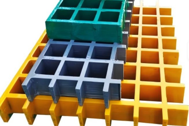
Ask a structural engineer to review a switchyard walkway and you will get a deflection check, a load table and a note about expansion gaps. Ask an electrical engineer the same question and you will get a different answer: what is the deck doing to the resistance of the current path through a person standing on it, and does it still do that after five years of dust, salt and cable-pulling grit? Both reviews matter, and only one of them is usually written down.
This guide covers the electrical side. It sets out how step, touch and transfer potentials are quantified under IEEE Std 80, what the allowable voltage limits actually work out to for a given clearing time and surface layer, where an FRP grating deck genuinely helps, and the three cases where an insulating deck is worth nothing at all. It then covers the failure modes that turn a good specification into a liability — surface contamination, static charge, unbonded metallic items, and the two tests that decide whether the finished yard is safe.
If you are specifying grating for a substation, a battery room, a switchgear operating aisle or a transformer bund area, the material choice and the detailing rule below will be recognisable. If you are a fabricator asked to quote, they are the questions a competent client will put to you.
1. The Walking Surface Is Part of the Electrical Safety Case
In a substation, a single line-to-ground fault raises the potential of the entire grounding grid above remote earth. That rise is the ground potential rise, and it is not uniform: it is highest near the faulted structure and decays with distance and with depth into the soil. A person standing on the surface, or touching a bonded structure, sits at the intersection of two different potentials, and the difference is what drives current through the body.
Three quantities follow from that geometry:
- Touch voltage — the difference between the potential of a bonded metal structure (a hand) and the surface potential where the person is standing (the feet). The current path runs through the trunk, close to the heart, which is why the allowable touch voltage is the strictest number in the design.
- Step voltage — the difference in surface potential between two feet placed about one metre apart. The current path bypasses the heart, so the allowable value is roughly three to four times higher than the touch value.
- Transfer voltage — a touch voltage moved elsewhere: ground potential rise travelled out of the yard on a fence, pipe, cable sheath, rail or telecommunications conductor, and presented to a person standing on normal soil hundreds of metres away. Transfer cases are outside the grounding grid's protection and are a common source of shocks to people who never entered the yard.
The walking surface enters this picture in one place only: it sits in series with the body resistance and the foot contact resistance on the touch-voltage path. Raise the resistance of that layer by six or seven orders of magnitude, and the current available to flow through a person's legs collapses. That is the entire electrical argument for FRP grating in a switchyard — and, as sections 5 and 6 show, it is not the same as making the yard safe.
2. What You Are Actually Designing Against
The governing document is IEEE Std 80, Guide for Safety in AC Substation Grounding. Its definitions of the exposure modes are worth quoting, because specifications frequently paraphrase them loosely:
Touch voltage: the potential difference between the ground potential rise and the surface potential at the point where a person is standing while at the same time having a hand in contact with a grounded structure.
Two inputs decide the magnitude of the hazard, and both are electrical, not structural:
- Fault clearance time, ts — the total time the fault current flows, including the backup protection stage. Allowable body current scales as 1/√ts, so halving the clearance time allows roughly 40% more current. A station cleared in 0.5 s is a fundamentally different design problem from one cleared in 0.10 s by a fast differential scheme.
- The current that actually enters the grid — the symmetrical fault current reduced by the decrement factor Df (DC offset, asymmetrical component) and split between the grid and other return paths by the current division factor Sf (cable sheaths, overhead static wires, metallic water mains). Ground potential rise is GPR = Df · Sf · If · Rg, and every one of those four factors is routinely estimated too optimistically.
A specification that says “grating shall be non-conductive” tells the fabricator nothing about the hazard. A specification that states the fault clearance time, the surface layer resistivity and thickness, and the required verification tests tells them exactly what has to survive.
3. The Tolerable-Voltage Equations, and What They Produce
The IEEE 80 limits are simple to apply once the surface layer is defined. The allowable body current for a 50 kg or 70 kg person is:
IB = k / √ts where k = 0.116 (50 kg) or 0.157 (70 kg), ts in seconds
The tolerable voltages add the resistance of the body (taken as 1000 Ω) to the foot resistance, with one foot in the circuit for a touch and both feet in series for a step:
Etouch = (1000 + 1.5 · Cs · ρs) · IB Estep = (1000 + 6.0 · Cs · ρs) · IB
where ρs is the resistivity of the surface layer and Cs is the surface layer derating factor:
Cs = 1 − 0.09 (1 − ρ / ρs) / (2 hs + 0.09)
with ρ the resistivity of the native soil and hs the thickness of the surface layer in metres. Work the numbers for a 100 mm layer of clean crushed rock at 3000 Ω·m over 100 Ω·m native soil and Cs comes out at 0.700, which produces the following limits:
| Fault clearance time ts | Allowable body current, 50 kg / 70 kg | Etouch, 50 kg / 70 kg | Estep, 50 kg / 70 kg |
|---|---|---|---|
| 0.10 s | 0.367 A / 0.496 A | 1522 V / 2060 V | 4989 V / 6752 V |
| 0.25 s | 0.232 A / 0.314 A | 963 V / 1303 V | 3155 V / 4270 V |
| 0.50 s | 0.164 A / 0.222 A | 681 V / 921 V | 2231 V / 3020 V |
| 1.00 s | 0.116 A / 0.157 A | 481 V / 652 V | 1578 V / 2135 V |
Assumptions: ρs = 3000 Ω·m, hs = 0.10 m, ρ = 100 Ω·m, so Cs = 0.700 in every row. Only ts varies.
Three conclusions follow, and they are the ones that decide whether you even need a special deck surface:
- On a proper gravel layer, the touch limit is already in the hundreds of volts. A station whose worst-case mesh voltage sits at 400 V is compliant at 0.5 s with the 70 kg curve and non-compliant at 1.0 s with the 50 kg curve. The same physical yard passes or fails on the protection settings and on which body weight curve the owner adopts.
- Remove the surface layer and the picture changes completely. Bare wet soil under the same grid gives an allowable touch voltage of 255 V at 0.5 s for 70 kg, because 1.5 · Cs · ρs collapses from 3150 Ω to 150 Ω. The single cheapest safety upgrade in most ageing switchyards is not the grounding grid — it is 100 mm of correctly graded crushed rock, maintained at thickness.
- Do not mix criteria. The 50 V figure quoted in European low-voltage installation practice and in general electrical-safety guidance describes a different scenario — typically an unfaulted, touchable installation with no surface treatment and no fault-current analysis. Applying 50 V as the acceptance limit for a 132 kV yard would make every grid in the world illegal; applying IEEE 80 limits to a low-voltage distribution board is equally wrong. State which criterion governs, and apply it consistently.
4. The Surface Layer Is Doing Most of the Work
Because Cs saturates once ρs is much greater than the native soil resistivity, the choice between gravel, granite chippings and asphalt matters far less than most specifications assume. Thickness matters more.
| Surface material | Typical ρs | Cs at hs = 50 mm | Cs at hs = 100 mm | Cs at hs = 150 mm |
|---|---|---|---|---|
| Wet native soil, no layer | 100 Ω·m | 1.000 | 1.000 | 1.000 |
| Sealed dry concrete | 2000 Ω·m | 0.550 | 0.705 | 0.781 |
| Crushed rock, clean | 3000 Ω·m | 0.542 | 0.700 | 0.777 |
| Washed granite chippings | 5000 Ω·m | 0.536 | 0.696 | 0.774 |
| Asphalt / bituminous layer | 8000 Ω·m | 0.532 | 0.694 | 0.772 |
Native soil ρ = 100 Ω·m throughout. Going from 50 mm to 150 mm of gravel lifts Cs from 0.542 to 0.777 — that is a 43% increase in allowable touch voltage from aggregate depth alone. The apparent contradiction with the material choice is worth understanding: at fixed thickness, raising ρs from 3000 to 8000 Ω·m lowers Cs slightly, from 0.700 to 0.694. Cs saturates because it is a correction to the foot resistance rather than the foot resistance itself. The benefit of a more resistive aggregate appears in the product Cs · ρs, which rises from 2100 Ω to 5548 Ω. That is the term that sits next to the 1000 Ω body resistance in the equation — and it is why thickness and resistivity both matter, in that order.
The operational consequence is uncomfortable: a gravel layer that has been contaminated with clay, compacted by vehicle traffic, or washed into the subsoil by years of drainage is no longer a 100 mm layer, and the design calculation no longer applies. Gravel resistivity should be measured, and thickness verified, as part of the periodic grounding review — not assumed from the original as-built drawing.
5. What an FRP Deck Changes, and Three Things It Does Not
An FRP grating panel is a glass fibre reinforced thermoset laminate. Its dry dielectric strength is typically above 10 kV/mm and its measured surface resistance is in the insulating range, so a worker standing on the panel is connected to the surface beneath it only through the panel itself. In electrical terms, the foot resistance in the touch-voltage equation is no longer dominated by the gravel layer — it is dominated by the panel, which is orders of magnitude more resistive.
That produces real benefits in service:
- No metallic path through the walking surface, so the deck cannot carry fault current or create a parallel return path inside the yard.
- No galvanic couple: stainless clips on FRP do not start the corrosion cycle that galvanised steel grating begins within the first years in a coastal or chemical yard.
- No coating to maintain, no spark risk from steel-to-steel contact, and no significant weight penalty on an existing steel support frame — FRP panels run at roughly a quarter of the weight of equivalent steel bar grating.
Three things it does not do, and all three appear in specifications that have been copied between projects:
- It does not protect a person standing on the yard beside the deck. Touch and step voltages are properties of the grounding grid and the soil, not of the panel. A walkway is normally a small fraction of the accessible area, and the worker at the bottom of the access ladder is exposed to the same mesh voltage as before.
- It does not remove the requirement for the ground grid or for bonding. The grid is what clears the fault and holds the yard at a survivable potential. FRP decks are an additional measure that removes one exposure path for one population of people, on one surface. Any metal structure the worker can touch — handrail posts, cable tray, equipment enclosures, transformer tanks — must still be bonded to the grid as designed.
- It provides no protection at all against bridging. An insulating platform interrupts the hand-to-feet path. If the worker simultaneously contacts two items at different potentials — a hand on an energised part and a shoulder against a bonded frame, or both hands on different phases — the current path bypasses the platform entirely. This is the same principle that makes insulating mats and platforms conditional protective measures rather than substitutes for isolation, and it must be written into the working method, not just assumed from the material datasheet.
Put the rule in the switching schedule: personnel working from an insulating deck must not be in simultaneous contact with the deck and with any bonded or energised conductive item. The material cannot enforce that; the procedure has to.
6. An Insulating Deck Is Not an Infinite Resistor
Two physical paths limit how much protection a composite panel can give. The first is capacitive coupling. A panel behaves as a capacitor formed by two conductive surfaces separated by a dielectric, and at power frequency that capacitance has a finite impedance:
| Panel | Capacitance, 1 m² | Impedance at 50 / 60 Hz | Capacitive current at 1 kV / 10 kV |
|---|---|---|---|
| 38 mm thick, εr = 5.5 | 1282 pF | 2.48 MΩ / 2.07 MΩ | 0.40 mA / 4.03 mA |
| 25 mm thick, εr = 5.5 | 1948 pF | 1.63 MΩ / 1.36 MΩ | 0.61 mA / 6.12 mA |
| 38 mm thick, 2 m² loaded area, εr = 4.5 | 2097 pF | 1.52 MΩ / 1.26 MΩ | 0.66 mA / 6.59 mA |
These are order-of-magnitude figures for a dry, clean panel, and the conclusion is reassuring: a few milliamps at 10 kV is two orders of magnitude below the 0.116 A fibrillation threshold at 0.5 s. The useful design lessons are the trends, not the absolute values. The current scales with panel area and inversely with thickness — a thin, large panel over any grounded metal surface behaves far less like an insulator than a thick panel on an open frame. Where the deck is credited as a protective measure, specify the panel depth for the electrical case as well as the structural one, and avoid bonding a conductive surface directly beneath it.
The second path is far less reassuring. Surface contamination and moisture produce a resistive film on the surface, in parallel with the capacitance and usually far lower in resistance. The international test method for this property is the surface resistance measurement of non-metallic materials in IEC 60079-0, which conditions the specimen for at least 24 hours at 23 °C and 50% relative humidity, applies 500 V DC for 65 s between two electrodes, and applies a limit of 1 GΩ at 50% RH — relaxed to 100 GΩ at 30% RH. A clean, dry FRP panel passes comfortably. The same panel, with a month of metal grinding dust and a light rain film, is a different specimen, and no datasheet value covers it.
Where contamination is unavoidable, the material properties that matter are tracking and erosion resistance rather than volume resistivity. Specify a resin system and surface construction qualified by comparative tracking index testing to IEC 60112, and where the site has a history of surface flashover, verify inclined-plane tracking per ASTM D2303 or IEC 60587. Combine that with a cleaning interval that the operations team will actually keep: a written quarterly clean of an accessible deck is a real safety measure; an annual clean of a deck nobody can reach is a document.
7. Static Charge: Where Insulating Grating Becomes the Wrong Answer
The property that makes FRP valuable on a switchyard walkway is a liability where flammable vapour may be present. Walking on an insulating panel generates and accumulates charge, and a discharge from a person at a few kilovolts is an ignition source in a battery room, a hydrogen-cooled generator area, an oil-handling or bunded transformer area, and during gas handling for SF6-filled equipment.
Where static dissipation is required, specify a conductive or static-dissipative grade of grating rather than standard insulating material, and ground it as the manufacturer directs. The relevant benchmark is NFPA 77, whose conductive-surface guidance gives an average surface resistivity of approximately 2.5 × 10³ to 1 × 10⁶ Ω per lineal foot, with the important caveat that the values apply only when the product is clean and grounded, and with a recommendation of at least four grounding attachments at the corners of each panel section. IEC 60079-0 gives the practical ceiling of 1 GΩ under its test conditions. Both figures are meaningless without the mechanical connection to earth, and that connection is a maintenance item: a carbon-loaded panel whose grounding strap was cut during a cable pull is an insulating panel again.
The conflict between the two objectives is real and cannot be designed away with one product:
| Location in the yard | Governing hazard | Correct deck specification |
|---|---|---|
| Access walkways over cable trenches and cable trays | Touch voltage to bonded tray and frames | Standard insulating FRP grating, Class 1 fire rated, 38 mm minimum depth, UV stabilised |
| Switchgear operating aisle, secondary equipment corridors | Touch voltage to enclosures; clean and dry environment | Insulating FRP grating or insulating floor covering; surface resistance verified at handover |
| Battery room, hydrogen areas | Static discharge igniting explosive atmosphere | Conductive or static-dissipative FRP grating, grounded at four corners, bonding continuity in the inspection routine |
| Transformer bund and oil-handling areas | Static discharge plus hydrocarbon spill; chemical exposure | Static-dissipative vinyl ester grating with documented chemical resistance to the specific oil and solvent |
| Outdoor gantry and equipment platforms, coastal sites | Corrosion, UV, wind-borne salt, occasional standing water | Insulating FRP with UV-stabilised surface veil and anti-slip grit; cleaning interval written into the maintenance plan |
Note what the table does not allow: one grating grade across the whole site. If the specification carries a single line item for “FRP grating, anti-slip” and the same panel is installed in the switchgear aisle and in the battery room, one of those two locations has the wrong material.
8. Handrail, Toe Boards and Bonding: The Details That Undo the Design
Handrail is where the electrical and structural arguments collide most visibly, because a handrail is exactly the kind of item a person holds while standing on the deck.
- An FRP handrail interrupts the hand-to-feet path in the same way the deck interrupts the foot path, and it is the natural choice on an FRP walkway for that reason. Confirm the structural case separately: guardrail geometry and the 200 lb concentrated load case come from the applicable walkway standard, and in utility installations that is generally the NESC rather than the NEC — NEC 90.2(B) excludes installations under the exclusive control of the utility. State the applicable code in the specification instead of leaving it to site interpretation.
- Never bond an FRP handrail. It is not a grounding conductor and cannot be made one. Bonding it accomplishes nothing electrically and introduces a conductive item at hand height, which is the opposite of the intent. Where static dissipation is the objective, use the conductive grade and follow the manufacturer's grounding scheme.
- Unbonded metal is worse than bonded metal. A steel gate frame, a temporary guard, a scaffold tube or a portable earthing stick left leaning against a structure can sit at a completely different potential from the grid during a fault. Transfer potential through unbonded metallic items is a classic cause of shock to people who were not even touching the electrical installation. If it is metal and permanent, it is bonded; if it is metal and temporary, it is removed before energisation.
- Toe boards and kick plates. A non-conductive toe board keeps dropped tools from bridging between the deck and an energised part below — a small detail with a disproportionate effect on arc-flash and short-circuit risk during maintenance.
9. Fire, Arc Exposure and UV: Keeping the Claims Honest
FRP grating for outdoor or indoor substation use is normally specified to a Class 1 / Class A surface burning characteristic, meaning a flame spread index of 25 or less and a smoke developed index of 450 or less when tested to ASTM E84. Where the deck forms part of an escape route, or where the yard is enclosed, smoke is the deciding parameter and a phenolic resin system with low smoke and low toxicity is the appropriate upgrade — at a cost in mechanical properties that must be designed for, not discovered later.
Two claims should be struck from any quotation that contains them:
- “Non-conductive, therefore arc-flash rated.” No. FRP grating is not an arc-rated product, and no walking surface substitutes for arc-rated clothing tested to ASTM F1506 or for the protective boundaries established under NFPA 70E. A deck reduces one exposure path; it does not reduce incident energy.
- “Maintenance free.” A deck whose protective value depends on being clean and dry is not maintenance free. It is low-maintenance relative to galvanised steel, which is a defensible commercial claim, and it is the reason the cleaning interval belongs in the specification rather than in a brochure.
For outdoor service, confirm UV stabilisation in the surface construction. Unprotected laminate chalks, the surface resin erodes, and the exposed fibre ends at the surface raise both water absorption and the risk of surface tracking over time — a slow degradation of exactly the property the electrical design relies on.
10. Support, Fixing and Expansion Detailing
The structural detailing of an FRP deck is covered in the load-table guidance elsewhere on this site, so only the items that interact with the electrical design are listed here:
- Deflection governs, not strength. Pultruded and moulded FRP have a modulus roughly an order of magnitude below steel. A panel chosen on ultimate load capacity alone will sag under the working load, pond water, and defeat its own drainage and cleaning assumptions. Specify panel depth against a deflection limit, not against a catalogue ultimate figure.
- Thermal movement is about twice that of steel. Provide expansion clearance at panel joints and at the perimeter, and use clip fixings that allow movement rather than bolts that lock several panels into one rigid, restrained field.
- Fasteners and clips. Stainless steel or composite clips and bolts are standard. Their role is fixing, not earthing — and in an area where the deck is credited as a protective measure, a continuous run of metallic splice plate across panels reinstates the conductive surface the design was trying to remove.
- Cut edges are sealed with resin. This closes the exposed fibre ends against moisture ingress and restores the fire and anti-tracking performance at the cut face. Sealed edges are also what allow the panel to be cut on site for a cable penetration without invalidating the electrical assumptions made for the deck.
11. Verification: The Tests That Decide Whether the Yard Is Actually Safe
The electrical case rests on two things being true: the grid performs as designed, and the deck performs as specified. Both are verifiable, and both are frequently skipped.
| Verification item | Method and reference | Acceptance / interpretation |
|---|---|---|
| Soil resistivity and layering | Wenner four-pin method, ρ = 2πaR, several electrode spacings | Layered soil model for the grid calculation; a single-spacing measurement cannot resolve a layered model |
| Grid resistance to remote earth | Fall-of-potential test to IEEE Std 81; current electrode at 5–10 × the maximum grid diagonal; plot the full traverse | Read the plateau, not the 61.8% ratio alone — the ratio is valid only for uniform soil and a truly remote electrode; agreement with the design model within roughly ±20% is a working tolerance |
| Touch and step voltage | Inject a controlled test current and measure surface potentials; scale to design fault current | Typically reserved for high-risk or post-incident investigation; agreement with the model within roughly ±25% |
| Bonding continuity and connectors | Connectors qualified to IEEE 837; field verification by continuity measurement and inspection against the approved detail | Every accessible metallic item in the yard bonded; connectors of the approved type, correctly installed before backfill |
| Surface resistance of the deck | IEC 60079-0 surface resistance test (500 V DC, 65 s, 23 °C / 50% RH) on a sample or the installed panel | ≤ 1 GΩ for static-dissipative and conductive grades; record under the conditions tested and reconcile with the grounding attachment check |
| Cleaning and condition | Visual inspection plus resistivity spot check of the surface layer thickness | Deck clean and dry in the areas credited; gravel layer at design thickness, not compacted or clay-contaminated |
A substation safety file should contain the as-built grid model, the soil resistivity survey, the fall-of-potential results, the bonded-connection inspection record and the deck surface-resistance test — five documents that together close the loop between the design intent and what is installed.
12. Five Mistakes That Recur in Substation Grating Specifications
| Mistake | Why it matters | Correct approach |
|---|---|---|
| Specifying “non-conductive grating” as the electrical requirement | Non-conductivity is a material property; it does not define the hazard, the exposure path or the verification | State the fault clearance time, surface layer resistivity and thickness, and the required surface-resistance test |
| Crediting the deck with protecting the whole yard | Touch and step potentials in the rest of the yard are unchanged; access ladders and adjacent equipment keep the exposure | Treat the deck as a supplementary measure for a defined walking surface, and keep the grid and bonding design independent of it |
| One grating grade across the whole site | Insulating and static-dissipative grades have opposing objectives; one location will be wrong | Split the bill of materials by area and by governing hazard, as in section 7 |
| Bonding an FRP handrail “for safety” | Adds a conductive item at hand height without any electrical function | Leave insulating handrail unbonded; use a grounded conductive grade only where static dissipation is required |
| Accepting a drawer of test certificates instead of the as-built record | Material certificates do not show whether the grid, the bonding or the installed surface perform as designed | Require the fall-of-potential results, connector inspection and installed deck surface-resistance record |
None of these are exotic. They recur because the structural and electrical specifications for a substation are usually written by different people, and the deck sits in the gap between them.
Grating, Handrail and Decking for Switchyards and Industrial Yards
We manufacture moulded and pultruded FRP grating in standard insulating and in conductive or static-dissipative grades, with Class 1 fire performance, UV-stabilised surfaces and cut-edge sealing, in panel depths and mesh sizes matched to the deflection limit of your support layout. Our moulded FRP grating for industrial walkways is the standard panel for access decks, and the high-density moulded grating range covers heavier load classes and aggressive atmospheres. For handrail and guardrail, the insulating FRP guardrail system provides a non-conductive barrier at hand height. Send us the yard layout, the panel spans and support condition, the governing hazard for each area, and the load case — we will return the panel schedule with the resin system, the fire and surface-resistance data, and the fixing detail.
Related reading: FRP grating load tables: reading uniform and concentrated loads · FRP grating and handrail condition assessment: inspection intervals and repair triggers · stair tread slip resistance: standards for FRP walkways · pultruded FRP cable tray systems for corrosive environments · FRP electrical insulation: 3240 epoxy glass laminates and components
Need help selecting FRP products?
Our engineers answer technical questions free of charge.
Ask an Engineer on WhatsApp