
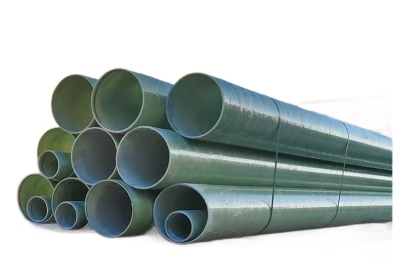
A free-standing FRP stack is a slender cantilever whose mass is roughly one-third that of the equivalent steel shell and whose axial laminate modulus is about one-tenth as high. Both of those facts push it in the same direction: the frequency of the first bending mode drops, the critical wind speed at which vortices shed in step with that frequency drops with it, and the structure ends up in the range of wind speeds that occur dozens of times a year rather than once in a design lifetime. Wind, not internal pressure, sizes the shell; vortex shedding, not static drag, usually decides whether the shell you drew is acceptable.
That would be manageable if a code told you how to comply. It does not. The only ASTM guide written specifically for FRP chimney construction, ASTM D5364-14(2024), is explicitly limited to FRP liners inside a supporting concrete shell and states that it is not applicable to other FRP cylindrical structures. ASME STS-1-2021 covers steel stacks, including guyed ones. The most complete national rules for FRP flue design are in GB/T 50051-2021 Chapter 9, which addresses FRP flue liners, including self-supporting ones.
So a free-standing FRP stack is designed by assembling three families of documents: a wind and seismic loading basis, a chimney structural practice, and a laminate design code. This guide sets out that basis and then works through the numbers on a single 25 m stack so that every step is visible. The sections on vortex shedding, Scruton number and guy wire design quote the criteria as they appear in ASCE 7-22, EN 1991-1-4 Annex E, ASME STS-1 and GB/T 50051-2021; where a value is good practice rather than a code requirement, it is labelled as such.
1. Why an FRP Stack Behaves Differently From a Steel One
Four material differences drive the structural behaviour, and only one of them helps you.
- Modulus. A filament-wound E-glass/vinyl ester structural laminate sits in the 15–25 GPa band. Structural steel is 200 GPa. For the same geometry the FRP shell is roughly 10 times more flexible.
- Density. Laminate density is about 1.8 g/cm³ against 7.85 g/cm³ for steel. So the mass per unit length falls to roughly a third, not a tenth, because the FRP shell has to be thicker to carry the same load.
- Specific stiffness. Dividing modulus by density gives about 10 × 10&sup6; m for GFRP against 25 × 10&sup6; m for steel. FRP is about 2.5 times softer per kilogram, which is why an FRP stack is lighter but lower frequency.
- Damping. Composite laminates dissipate noticeably more energy than welded steel. That is the one favourable item, and it matters enormously because the amplitude of vortex-induced vibration scales inversely with damping.
| Property | Filament-wound GFRP shell | Carbon steel shell | Structural consequence |
|---|---|---|---|
| Density | 1.8 g/cm³ | 7.85 g/cm³ | Smaller foundation, but far less dead load to resist uplift |
| Axial modulus | 15–25 GPa | 200 GPa | Lower first-mode frequency, larger static deflection |
| Tensile strength (structural layer) | 200–300 MPa | 400 MPa and above | Strength is rarely the governing check — strain is |
| Allowable design strain | 0.20–0.35% depending on code and resin | Yield at about 0.12% | Strain-limited design, not stress-limited |
| Thermal conductivity | 0.3 W/m·K | 50 W/m·K | Gas stays warmer; external insulation often unnecessary |
| Coefficient of thermal expansion | 8–12 × 10⁻⁶ /K axial | 12 × 10⁻⁶ /K | Thermal movement comparable; detail the duct joint anyway |
| Damping ratio (typical) | 0.5–2% | 0.2% | Higher damping suppresses vortex response — but it must be justified |
The practical message is that an FRP stack is not a steel stack with a different material card. It is a structure whose governing limit state is dynamic, whose mass damping is low because the structure is light, and whose design therefore has to be demonstrated with a vortex-shedding calculation rather than assumed from a height-to-diameter rule.
2. The Design Basis: Assembling the Three Families
Establish the hierarchy before any calculation, because the three families answer different questions and they do not overlap.
| Document | What it provides | What it does not cover |
|---|---|---|
| GB/T 50051-2021, Chapter 9 | FRP flue liner and self-supporting FRP flue design: 30-year design life, layup rules, material partial factors, temperature derating, minimum structural layer thickness, dynamic wind criteria | It is written as part of a chimney standard, so the surrounding concrete or steel structure is outside its scope |
| ASTM D5364-14(2024) | Design, fabrication and erection guidance for FRP liners: dead, wind, earthquake, thermal and circumferential pressure loads, load and resistance factors, allowable longitudinal and circumferential stresses, design limits, deflections, field joints and QA/QC | Expressly limited to liners within a supporting concrete shell; not applicable to free-standing FRP cylinders |
| ASME STS-1-2021 | Structural practice for stacks: dynamic wind and seismic vibration, guy design, lightning protection, access, fabrication, inspection and maintenance | Material rules and stress allowables are for steel |
| CICIND model code | International steel chimney practice; widely used as a benchmark on industrial chimneys | Steel-specific |
| ASCE 7-22 | Wind loads for chimneys and similar structures (Chapter 29 force method, Chapter 26 velocity pressure) and seismic coefficients for nonbuilding structures (Table 15.4-2) | It gives loads, not FRP allowables |
| EN 1991-1-4 Annex E | Vortex-shedding criteria: critical wind speed, Strouhal number, Scruton number and the 1.25 × vm screening rule | Loads only, not laminate design |
| ASTM D3299 / ASME RTP-1 / EN 13121-3 | Laminate design for corrosion-resistant GRP equipment: design strains, design factors, test factors | Written for vessels and tanks; the same principles are applied to shells |
| EN 13706-3 | Declared minimum properties for pultruded structural sections used for platforms, ladders and internal framing | Pultruded sections, not wound shells |
Write the basis of design as a one-page statement before the stress report: design wind speed and return period, exposure category, terrain, seismic parameters, design life, resin selection by gas temperature and chemistry, and the specific list of clauses you will comply with. A stack specification that cites only "ASME STS-1" for an FRP shell tells a reviewer nothing about the material allowables being used.
3. Along-Wind Design: Velocity Pressure, Force Coefficient, Base Moment
ASCE 7-22 Chapter 29 treats chimneys and similar structures as isolated bodies with a force coefficient rather than a building pressure map. In SI units the velocity pressure is:
qz = 0.613 · Kz · Kzt · Kd · Ke · V² (N/m², with V in m/s)
The force on a segment is F = qz · G · Cf · Af, where Af is the projected area and Cf comes from Figure 29.5-1. Three things in that figure matter to a stack designer: the coefficient depends on the height-to-diameter ratio, it depends on surface roughness, and the roughness categories are the aerodynamic equivalent of helical strakes.
| Cross-section and surface | h/D = 1 | h/D = 7 | h/D = 25 | Comment |
|---|---|---|---|---|
| Round, moderately smooth (D√qz above the transition) | 0.5 | 0.6 | 0.7 | The band a bare FRP shell sits in |
| Round, rough (protrusions about 0.02 D) | 0.7 | 0.8 | 0.9 | Ladders, platforms, pipe runs |
| Round, very rough (protrusions about 0.08 D) | 0.8 | 1.0 | 1.2 | Helical strakes and heavy appurtenances |
| Round, below the transition (D√qz small) | 0.7 | 0.8 | 1.2 | Small diameter or low velocity pressure |
| Square, wind normal to face | 1.3 | 1.4 | 2.0 | Shown for reference; avoid square flues in wind-critical locations |
Which row applies is decided by the product D√qz, with D in metres and qz in N/m². Take a 25 m stack, 1.6 m outside diameter, in a 45 m/s three-second gust region with exposure category C, Kz = 1.10 at two-thirds height, a directionality factor of 0.95 for a round chimney, and a gust effect factor of 0.85:
- qz = 0.613 × 1.10 × 1.00 × 0.95 × 1.00 × 45² = 1,297 N/m² (about 27 psf).
- D√qz = 1.6 × 36.0 = 57.6, comfortably above the transition, so the moderately smooth row applies and Cf = 0.7 at this slenderness.
- F = 1,297 × 0.85 × 0.7 × (1.6 × 25) = 30.9 kN, acting at mid-height.
- Mbase = 30.9 × 12.5 = 386 kN·m.
Now check the shell. For a thin ring of radius r and thickness t the section modulus is approximately πr²t, so the bending stress is M/(πr²t):
σ = 386,000 / (π × 0.8² × 0.012) = 16.0 MPa, i.e. an elastic strain of 0.089%
Against a 0.2% design strain limit that is a utilisation of 0.44, and back-solving the thickness needed for the moment alone gives only about 5.3 mm. The 12 mm structural layer on a stack of this size is not there for along-wind bending. It is there for local buckling under combined bending and compression, for the stress concentrations at the flue inlet and any platform brackets, for a 2 mm abrasion and erosion allowance in the inlet zone, for handling and erection loads, and for stiffness during transport. Say that explicitly in the calculation report, because otherwise a reviewer will ask why the shell is twice as thick as the bending check demands — and the honest answer is that bending is not the governing limit state.
4. Vortex Shedding: The Check That Decides Whether the Shell Works
Alternate vortices shed from a circular cylinder in wind, producing a lift force perpendicular to the flow. When the shedding frequency coincides with a natural frequency the structure locks in and vibrates across-wind at large amplitude. EN 1991-1-4 Annex E states the screening rule plainly: vortex shedding need not be investigated when the critical wind speed exceeds 1.25 times the characteristic 10-minute mean wind speed at the relevant section.
vcrit,i = b · ni,y / St
For a circular section the Strouhal number is 0.18 in the Eurocode table; ASCE-based stack practice commonly uses 0.18–0.20, and higher values apply only in the supercritical Reynolds regime, which is rare for stacks. Compute the frequency first. For a uniform cantilever of mass m per unit length, height H and flexural rigidity EI:
n1 = (1.8751² / 2π) · √(EI / (m H⁴))
For our stack: r = 0.8 m, t = 12 mm, so I = πr³t = 0.0193 m⁴; with E = 18 GPa, EI = 3.47 × 10⁸ N·m². The shell alone weighs πDtρ = 109 kg/m; allow 120 kg/m for the liner, top flange and appurtenances. Then n1 = 1.52 Hz.
vcrit = 1.52 × 1.6 / 0.18 = 13.5 m/s
Compare that with 1.25 × vm. In a 45 m/s gust region the 10-minute mean wind at stack height is typically 25–30 m/s, so the threshold is around 34 m/s and 13.5 m/s fails it by a wide margin. This is the sentence that has to appear in the report: the critical wind speed is not merely below the screening threshold, it is a speed the site experiences on many days each year. Under those conditions a fatigue assessment and a response amplitude estimate are not optional extras.
The second parameter is the Scruton number, the mass-damping group that controls how large the locked-in amplitude becomes. EN 1991-1-4 defines it with the logarithmic decrement, and the air density recommended for vortex-shedding conditions is 1.25 kg/m³:
Sc = 2 δ m / (ρ b²) where δ = 2πζ (logarithmic decrement) and ζ is the damping ratio
For our 120 kg/m stack at 1.6 m diameter:
| Damping ratio ζ | Log decrement δ | Scruton number Sc | Expected response |
|---|---|---|---|
| 0.5% | 0.031 | 2.4 | Very large amplitude; rhythmic, persistent oscillation |
| 1.0% | 0.063 | 4.7 | Large amplitude; mitigation almost certainly required |
| 2.0% | 0.126 | 9.4 | Elevated but controllable with careful detail design |
| 3.0% | 0.188 | 14.1 | Modest response; regular strake or damper provision usually unnecessary |
Published guidance is that response is small above roughly Sc = 15 and can be very large below about Sc = 5; the transition is steep, which is why an error in the damping assumption changes the answer qualitatively rather than by a few percent.
Put the same mass-damping number on a steel shell: at 355 kg/m and 0.2% damping, Sc = 2.8 — also low. The published research on FRP chimneys reached the same conclusion from the other direction: with no national code for FRP chimney design, the analysis found FRP chimneys to be particularly vulnerable to across-wind oscillation from vortex shedding because the laminate stiffness and the mass are both low. FRP is not being singled out unfairly; it is simply lighter, and lightness in a slender structure is exactly the wrong property.
Damping is the weakest number in the whole calculation and it cannot be calculated from geometry. If a stack is vibration-sensitive, plan an ambient-vibration or pluck test on the erected shell and use the measured logarithmic decrement for the final response estimate. It takes an afternoon and it can move the design from "add strakes and re-check the foundation" to "no mitigation required".
5. Mitigation: Strakes, Dampers, Mass and Geometry
There are four families of remedy and they work by different mechanisms, so mix them deliberately.
Aerodynamic devices. The helical strake is the default on industrial stacks. The geometry in ASME STS-1 practice is three starts at 120 degrees, strake width one tenth of the diameter, pitch five diameters, fitted over the top third of the shell. GB/T 50051-2021 writes the same geometry for steel chimneys as three helical plates at least 6 mm thick, width one tenth of the outer diameter and pitch five times the outer diameter. On our 1.6 m stack that means 0.16 m wide fins at 8 m pitch, from about 16.7 m up to the top. Strakes do not remove shedding — they break the correlation along the length and cut the response, typically by the order of 70–90% in published tests.
The drag penalty is real. A straked shell moves into a rougher force-coefficient category, and Cf at this slenderness goes from 0.7 to somewhere between 0.9 and 1.2. That is 29% to 71% more along-wind moment on the straked portion, and the base moment and foundation have to be re-checked with the higher coefficient. Published VIV literature generally quotes a drag increase in the region of 20–40%; the code coefficient is the defensible number to design to, so use the code and let the foundation absorb the difference.
Segmented strakes. Short, randomly placed segments are not recognised by the stack standards and stacks fitted with them have been observed to keep vibrating. If a continuous helix is blocked by a stiffening ring, ASME STS-1 permits local cuts to clear the attachment, with the strake started and stopped immediately either side of the interruption. Partial coverage, such as omitting the strake behind a flare tip, has to be justified rather than assumed.
Structural remedies. A tuned mass damper at the top raises the effective damping; it is tuned to the measured first-mode frequency and typically uses a mass of a percent or two of the modal mass. Increasing the shell thickness raises the frequency a little and raises Sc through added mass. Adding a brace, a guy level, or reducing height raises the critical wind speed directly because n1 rises with the inverse square of the effective length.
| Option | Effect on the numbers | Watch out for |
|---|---|---|
| Helical strakes, 3 starts, top third | Cuts lock-in amplitude by roughly 70–90%; leaves vcrit unchanged | Cf rises to 0.9–1.2; foundation and base ring must be re-checked |
| Tuned mass damper at top | Raises effective damping, therefore Sc, without touching drag | Needs a measured frequency; internal access for maintenance |
| Thicker structural layer | Raises n1 slightly and raises Sc through mass | Cost and weight rise; effectiveness is modest for a given thickness |
| One guy level at about two-thirds height | Raises n1 substantially; removes most of the base moment | Introduces guy pretension, deadman and inspection obligations (Section 8) |
| Reduce height, increase exit diameter | Raises vcrit by lowering slenderness | Conflict with dispersion requirement for the plume |
One geometry rule is worth carrying across even though it is written for steel: GB/T 50051-2021 advises that a self-supporting steel chimney should not exceed a height-to-diameter ratio of about 30, and that exceeding it requires either an enlarged lower section or explicit vibration measures. An FRP shell with a lower modulus has no business being more slender than that without a full dynamic check.
6. Laminate Design: Strain Limits, Not Stress Fractions
Fracture of a GRP laminate is strain-driven, and every design code for corrosion-resistant GRP equipment is built around a limiting strain rather than a fraction of ultimate stress. Reasonable people disagree about the number, so the specification has to say which one applies.
| Code basis | Design limit | Starting point in the calculation |
|---|---|---|
| BS 4994 (withdrawn 2016, still cited for legacy specifications) | Maximum allowable design strain in corrosion-resistant GRP equipment: 0.2% | σallow = 0.002 × E; for E = 18 GPa that is 36 MPa |
| EN 13121-3:2016 | Limit design strain tabulated by resin and reinforcement, broadly 0.25–0.35% at ambient and reducing at elevated temperature; test strain limited to 1.3 × the design strain | Read the table for your exact resin and reinforcement, then apply the temperature case |
| EN 13121-3 design factors | Minimum overall design factor of 4 (basic design) up to 8 depending on material test evidence and long-term data; minimum buckling design factor 2.7 to 4.0; γM = 1.4, γF = 1.35 permanent / 1.5 variable | Factors depend on how much material testing you can show |
| GB/T 50051-2021, Chapter 9 | Partial factor of 1.55 in tension and 2.5 in compression; temperature reduction from 1.0 at 20 °C to 0.80 in tension and 0.60 in compression at 90 °C; minimum structural layer thickness D/1000; 30-year design life | Derate first, then check strain; the compression factor is severe |
Two consequences follow for a stack shell. First, the compression derating is what usually governs a flue carrying hot gas: at 90 °C a compression partial factor of 2.5 combined with a 0.60 temperature factor is a far larger penalty than anything a wind check applies, and it is applied to the axial compression from self-weight and bending that a cantilever always has. Second, only the structural layer counts. The resin-rich inner veil and the chopped-strand layer behind it are the corrosion barrier, typically a resin-rich surface layer of about 0.25–0.5 mm followed by about 2 mm of chopped strand at roughly 27 ± 5% glass content — the same barrier build-up specified for filament-wound chemical tanks to ASTM D3299 — and the outer UV-resistant layer carries no structural credit either. Do not add them into t when you check bending stress, however tempting the arithmetic looks.
The minimum D/1000 structural layer in GB/T 50051-2021 is a floor, not a target. For a 1.6 m flue it works out at 1.6 mm, which no fabricator would build and no client would accept for handling, buckling and erosion allowances. Expect a self-supporting FRP flue in this size range to end up between 6 and 15 mm of structural laminate once buckling, the inlet zone, and the abrasion allowance are accounted for.
7. Base Ring, Anchorage and Uplift: The Detail That Catches Everyone
Here is the trap. An FRP stack is light, so the dead load that resists overturning is small, so the eccentricity M/P is enormous and the anchor bolts go into tension. For our stack, the shell weighs 120 × 25 × 9.81 = 29.4 kN, and with a base ring, ladder and accessories call the total dead load 45 kN. Against a service base moment of 386 kN·m the eccentricity is 8.6 m, an order of magnitude greater than the 0.8 m radius. The base is in overturning in every sense that matters.
Size the anchors for that. On an eight-bolt circle of 1.8 m diameter, the moment alone produces about 54 kN per bolt, reduced by roughly 6 kN of dead-load relief, so about 48 kN per bolt at service load before load factors. Multiply by the load factor for the governing combination and check it against the bolt's tensile capacity with the fitting efficiency included. Then check the local laminate: the bolt load enters the shell through the base ring, so the shell needs a thickened laminate at the base, and the base ring needs to be continuous around the full circumference rather than a set of discrete brackets.
- Leveling and grout. Level with nuts or shims, then grout under a full ring so the shell bears on the foundation uniformly rather than on three high points.
- Overturning and sliding factors. Published FRP chimney practice works to a factor against overturning of at least 1.5 and against sliding of at least 1.3; confirm the requirement in the project's foundation basis.
- Thermal movement at the duct. A 25 m shell moving through a 60 K range moves roughly 8–12 × 10⁻⁶ × 25,000 × 60 ≈ 13–18 mm at the top connection. The flue gas inlet must therefore be connected through a flexible expansion joint, not bolted hard to a rigid duct; otherwise the duct becomes an unintended brace and the shell picks up a load path nobody designed.
- Corrosion at the base. The base ring, anchor bolts and grout sit in the wettest, most acidic part of the installation. Detail drainage away from the base and specify the bolt material for the environment, not for cost.
8. Guyed Stacks: Pretension, Safety Factor and Inspection
Guying transforms the structure: the shell becomes a beam on elastic supports, the base moment drops sharply, and the required shell thickness falls with it. It also introduces a set of maintenance obligations that are easy to promise at the quotation stage and easy to forget afterwards. ASME STS-1 is unusually specific about them, and the same rules are the sensible basis for an FRP stack on a guyed support system.
| Item | ASME STS-1 position | Practical value to specify |
|---|---|---|
| Guy wire material | Galvanised or otherwise protected against corrosion, or stainless steel strands; fittings galvanised | Match to the plant atmosphere; a coastal site justifies stainless or a heavier galvanised coating with re-inspection |
| Pretension | Value and procedure established by the designer; prestretched cable recommended so the cable does not stretch after installation | Industry practice sets pretension at roughly 8–15% of ultimate strength: too low invites galloping, too high invites aeolian vibration |
| Factored strength | Factor of safety on cable breaking strength of at least 3, with fitting efficiency considered | Multiply by any temperature or fatigue case; never quote the catalogue breaking load as capacity |
| Analysis cases | Hot and cold conditions both analysed, because differential thermal expansion between shell and cables changes the geometry and the tension | A stack carrying hot gas grows; that slackens the cables and increases lateral deflection |
| Attachment to shell | Shell reinforced at each attachment level with a continuous ring and stiffeners as required | Never bolt a single lug through a 12 mm FRP shell; distribute into a full ring plus longitudinal stiffeners |
| Inspection and maintenance | Frequent inspection of cables and verification of pretension; lubricate and verify tension every five years | Write the five-year cycle into the operating manual and the spares list |
Guyed configurations also change the vibration problem. With adequate pretension the guy modes are not usually critical, but slack cables gallop and over-tight cables fatigue at the terminations. A cable's fundamental frequency can be estimated as f = √(F/m)/(2L) for average tension F, mass per unit length m and unsupported length L, which is a useful check that the cable is not tuned to something that the wind can excite.
The shells themselves are wound on filament winding lines, and the same process variables that control pipe quality control the stack wall: fibre tension, resin pick-up, wind angle and cure. If you are assessing a supplier, ask for the commissioning records for the winding line — the process discipline behind the laminate — and read our guide to filament winding machine commissioning to see what those records should contain.
9. Details That Decide Whether the Stack Lasts Twenty Years
A stack fails from the inside long before it fails structurally, and the failures cluster in four places.
- The inlet zone. This is the wettest, slowest and most turbulent part of the gas path. It sees the highest rate of acid condensation, the greatest impingement erosion, and the largest thermal gradient. Specify a thicker abrasion allowance, a resin with filler selected for erosion resistance at the impingement areas, and the ability to inspect and repair the first few metres without dismantling anything.
- The duct connection. Covered above: a flexible joint, correctly supported, with the duct's own weight carried to the ground rather than to the stack.
- Access. Ladders, cages and platforms designed to the applicable access standard, with the attachment loads introduced into the shell through reinforced pads or rings. This is also the plant's only means of inspecting the shell, so make it usable.
- Lightning and static electricity. An FRP shell does not conduct. Lightning protection has to be deliberate: air termination, down conductor, and earthing, rather than an assumption that the shell is self-protecting. ASTM D5364 devotes a section to static build-up for good reason — dry particulate in a flue generates charge, and a conductive veil or an antistatic laminate with a defined surface resistivity plus a discharge path to earth is the answer. Products such as our antistatic FRP GRP flue are built on exactly that principle.
Wet stacks deserve their own note: the 2021 revision of GB/T 50051-2021 added provisions on preventing chimney rain, together with velocity limits for wet chimneys, for the simple reason that a wet stack at the wrong exit velocity rains dilute acid onto whatever is downwind of it, including the plant's own people and equipment.
10. Specification Checklist for a Free-Standing FRP Stack
Send the table below out with the enquiry. It converts a vague request for "an FRP stack, 25 metres, corrosion resistant" into a package that a structural reviewer can check.
| Item to require | Why it matters |
|---|---|
| Basis of design statement: wind speed and return period, exposure, seismic parameters, design life, gas temperature, chemistry and dew point | Every later calculation depends on it; without it the numbers cannot be audited |
| Dynamic wind check showing vcrit, the assumed damping and the resulting Scruton number, plus the fatigue assessment when vcrit is a frequently occurring speed | This is the check that governs; it must be in the submittal, not in a covering letter |
| Laminate schedule: barrier build-up with resin contents, structural layer thickness by analysis, outer UV layer, and the design strain used | Lets the buyer verify that the barrier is not counted as structure and that the strain limit matches the specified code |
| Resin selection by temperature and chemistry, with continuous service temperature and any temperature derating factors applied | Resin choice is the single biggest determinant of service life in a wet acid flue |
| Mitigation devices specified by geometry: strake width, pitch, number of starts and length, or damper mass and tuning frequency | Prevents a token strake installation that does not match the tested geometry |
| Base ring and anchor bolt design, with the uplift calculation and the load factors shown | Uplift, not bearing, governs the anchorage of a light stack |
| Expansion joint details at the duct and at any platform connection | Stops the surrounding steelwork becoming an unintended brace |
| Access and lightning protection designed to the applicable standards | Both are safety obligations and both are routinely omitted from FRP stack quotations |
| QA documentation: laminate thickness and Barcol hardness readings, cure records, visual inspection against a defect standard, and a leak or pressure test on joints | Converts "we built it carefully" into evidence |
| Inspection and maintenance plan covering the inlet zone, guy cables if fitted, and the lightning system | A stack is a 20–30 year asset only if it is inspected |
If a supplier cannot produce the dynamic wind check, that is not a documentation gap — it means the shell was sized by a rule of thumb, and on a structure with this little mass damping a rule of thumb is not a design.
Build the Shell, the Accessories and the Duct as One Package
We manufacture the corrosion-resistant flue and duct package itself, which means the inlet details, the abrasion allowance and the joint quality are decided by the same people who wind the shell. Our antistatic FRP GRP flue for high-temperature corrosive exhaust is built with a conductive path to earth for dry particulate service, and the shells are wound in-house on our own lines — see the CNC filament winding line we build for tank and pipe production for the process discipline behind them. Send us the gas conditions, the stack height and the site wind speed, and we will return the laminate schedule, the barrier resin recommendation and the dynamic wind check as one document.
Related reading: FRP flue and chimney liners for corrosive exhaust · FRP duct and hood fabrication: thickness, stiffeners and support for large spans · FRP tank and vessel field erection, joint lamination and on-site post-cure · FRP ladder and cage access systems to OSHA and EN ISO 14122
Need help selecting FRP products?
Our engineers answer technical questions free of charge.
Ask an Engineer on WhatsApp