
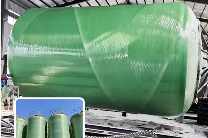
A filament winding machine that has been craned into position, wired, aligned and filled with resin is not yet a production asset. It is a machine that turns mandrels. The difference between the two states is commissioning, and in an FRP plant commissioning is almost entirely a measurement exercise: recording spindle runout, proving that the resin bath is delivering the right pick-up, proving that the fibre tension is what the recipe says, and proving that the first part cut off the mandrel meets a specification rather than just looking acceptable.
This guide sets out a commissioning sequence that produces evidence. It covers the four systems that decide whether the line ever makes a sellable part — machine geometry, mandrel preparation, resin impregnation and fibre tension — and it finishes with the cut-up test that converts all of it into numbers you can put in front of a customer. The values quoted come from ASTM D2996 and D3299, ASME RTP-1, EN 13706 and the published wet-winding literature; where a figure is a protocol target rather than a standard requirement, it is described as such.
1. Four Gates, in the Order They Should Be Closed
Commission a winder in the sequence below, and do not open the next gate until the previous one is signed off. Each gate produces a document; a machine that has no documents has not been commissioned, however well it runs.
- Geometry and synchronisation. Spindle, tailstock, carriage rails and the mandrel all line up, and the two motion axes deliver the commanded wind angle within tolerance. A machine that cannot hold an angle cannot hold a specification, because wall thickness on a wound part is a direct function of angle.
- Mandrel and release system. The mandrel is straight, clean, correctly tapered or collapsible, and the release system is proven to survive the cure cycle without the part locking onto the steel.
- Impregnation and tension. The bath delivers a repeatable resin pick-up, and the tension at laydown matches the value in the recipe, tow by tow, at production speed — not just at the crawl speed used for the dry run.
- Cut-up acceptance. A wound test section is destroyed in a controlled way, and the results — glass content, void content, Barcol hardness, wall thickness and burst pressure — are recorded against the specification limits.
The single most common commissioning failure is to accept the dry run as evidence for the wet run. Tension and pick-up both change when resin is in the system: wet tow carries more mass, the nip rollers impose drag, and the carriage has to accelerate with a heavier band. Calibrate wet, at speed, on the real mandrel.
2. Machine Geometry: What to Measure and What to Record
Wound wall thickness varies as the cosine of the angle error and the laydown position drifts with every millimetre of mandrel runout, so the geometry tolerances of a winder are much tighter than those of an assembly fixture. Record every value below in the commissioning report, both cold and after a two-hour thermal soak at production temperature.
| Item | What it controls | Commissioning target (protocol value) |
|---|---|---|
| Headstock spindle radial runout | Mandrel whip, laydown tracking, tension spikes | 0.05 mm or better at the chuck face |
| Tailstock concentricity to headstock | Long-mandrel sag and mid-span runout | 0.10 mm total indicator reading over the bed length |
| Carriage rail straightness and level | Constant fibre path length, so constant tension | 0.10 mm per metre in both planes |
| Mandrel mid-span runout when loaded | Angle error and resin pooling on one side | 0.5 mm, measured hot and at production speed |
| Chuck jaw grip and repeatability | Circularity of the article and demoulding force | 0.05 mm re-chuck repeatability |
| Axis synchronisation (angle accuracy) | Wall thickness, hoop to axial balance | Within ±1° of the commanded wind angle |
The ±1° figure is not arbitrary. The accepted winding angle for balanced FRP pipe is 54° measured from the pipe axis, and the published practice is to hold that at 54 ± 1°. Reproduce the same tolerance on whatever angle your recipe calls for. You can verify it without a laser tracker: wind a dry band on the mandrel, mark one revolution, and measure the axial advance. The angle then follows from the geometry:
tanθ = mandrel circumference / axial advance per revolution
For a 500 mm outside-diameter mandrel the circumference is 1571 mm, which makes the numbers very easy to check by hand.
| Wind angle from mandrel axis | Axial advance per revolution (mm) | Structural role |
|---|---|---|
| 90° (hoop) | 0 — mandrel rotates, carriage stationary | Hoops stress: internal pressure and burst |
| 75° | 421 | Pressure-dominated layer with a little axial capacity |
| 54.7° | 1111 | Balanced layer: the classic FRP pipe angle, balancing hoop and axial stress |
| 45° | 1571 | Balanced torsion and shear, common in shafts and drive tubes |
| 20° | 4316 | Axial stiffness and bending; low burst contribution |
Command a pattern and then verify the achieved advance against the commanded value rather than trusting the servo readout. On a 6 m mandrel a 1 mm error in pitch per revolution accumulates into resin-rich and fibre-rich bands, and those bands are where the pipe will fail in a burst test.
3. Mandrel Preparation: Taper, Cleanliness and Release
The mandrel defines the inner diameter, so it also defines the corrosion barrier surface — the surface that every chemical in the plant will touch. Two things have to be right before the first metre is wound: the mandrel has to come out without hydraulic force that damages the part, and the surface it leaves behind has to be smooth, resin-rich and free of defects.
Extraction strategy. There are three ways to get a wound part off a mandrel, and the taper question only applies to the first:
- Tapered steel mandrel, hydraulic or mechanical push. The mandrel is machined with a small draft along its length so the diameter grows enough to break the friction lock. Expressed as a ratio, 1:1000 to 1:200 is the practical band. On a 6 m mandrel that is a diameter change of 6 mm at 1:1000 or 30 mm at 1:200 — enough to release, small enough that the pipe still meets its bore tolerance. Steep tapers measured in degrees are only viable on short articles.
- Collapsible mandrels. Segmented or inflatable designs that reduce in diameter before extraction. More expensive and more maintenance, but they remove the taper constraint entirely and are the norm for large-diameter parts.
- Expendable mandrels. Eutectic salts, soluble plasters and low-melting-point alloys, dissolved or melted out. Used for complex or low-volume geometries where the mandrel cannot be withdrawn.
Surface condition. The mandrel must be dimensionally straight (±0.5 mm over its length is a reasonable target for a 6 m tube), free of weld spatter, dents and corrosion pits, and polished to a finish that will not transfer its texture into the pipe bore. Pits are the worst case: they trap resin, and the cured resin plug has to be chiselled out, taking mandrel surface with it. Inspect with a raking light along the full length before every production campaign, not once a year.
Release system. Three families are in general use, and the choice is a trade between cost per part, surface finish and temperature capability.
| Release system | Application | Typical performance | Watch out for |
|---|---|---|---|
| Paste wax (carnauba-based) | Condition with 5–7 coats, then one coat per part | Temperature tolerant to roughly 95 °C; excellent finish | Labour-intensive on a 6 m mandrel; needs a full re-condition after any stripping |
| PVA film | Sprayed or wiped on, allowed to dry to a film | Very reliable barrier release; the safest for a new or repaired mandrel | Water-based, so the drying time governs cycle time; can print a slightly duller finish |
| Semi-permanent polymer | Applied as a thin film, several releases per application | Lowest labour per part, best for high-volume lines | Requires an absolutely clean substrate; incompatible with some silicone residues |
Whichever system is chosen, the mandrel must be cleaned back to bare metal before the release goes on. Resin residue from the previous part is the single most common cause of a release failure, and a release failure on a large-diameter wound part usually means scrapping the part and dressing the mandrel.
4. The Resin Bath: Viscosity, Temperature and Pick-Up
In wet winding the resin bath is both the impregnation station and the metering station. Fibre comes off the creel dry, passes through the bath, and then through a wiping system — squeeze rollers, a doctor blade or a die — that removes the excess and sets the resin content of the laminate. Everything downstream of that nip is fixed.
Viscosity window. For glass fibre wet winding the usable window is roughly 500–1,500 mPa·s at the bath temperature. Below about 500 mPa·s the resin drains out of the tow before it reaches the mandrel, producing resin-starved, dry-looking laminate. Above about 2,000 mPa·s the tow will not wet out properly and the tension needed to pull it through the bath becomes high enough to damage or break filaments. Measure with a portable rotational viscometer in the bath, not from a sample pot, and log it at the start and end of every shift — viscosity climbs as styrene evaporates and as the working pot life is consumed.
Temperature control. Bath temperature is the main viscosity lever. Polyester and vinyl ester systems for FRP pipe are commonly run in the 40–50 °C band; epoxy wet-winding systems are formulated for a lower bath temperature with a much longer pot life; and in demanding wet-winding operations the resin itself may be held around 80–85 °C with a mandrel heated to 70–80 °C and a dip time of only one to two seconds. Choose the bath temperature from the resin supplier's viscosity curve, then hold it within ±2 °C. A bath that swings ten degrees produces a laminate that varies from dry to resin-rich along the length of one pipe.
Pick-up and resin content. The nip gap and roller pressure determine how much resin the tow carries away. The practical acceptance range for a wet-wound structural laminate is 30–45% resin by weight, which is the same statement as 55–70% glass content by weight. The corrosion barrier layer is deliberately different: for filament-wound atmospheric tanks the barrier glass content is specified at 27 ± 5% by weight, tested by ignition loss, because the barrier must be resin-rich to resist chemicals.
| Laminate layer | Glass content by weight (ASTM D2584) | Why |
|---|---|---|
| Corrosion barrier (liner) | 27 ± 5% | Resin-rich surface, no exposed fibre to wick chemicals into the wall |
| Structural filament-wound laminate | 55–70% | Maximum fibre per unit volume means maximum hoop strength and stiffness |
| Hand lay-up comparison | 25–35% | Shown for reference: contact moulding cannot reach filament-winding glass fractions |
Two mechanical details on the bath. First, fit an in-line filter on the return line and recirculate: it keeps cured particles and filler agglomerates out of the nip, which is where they cause scouring and dry spots. Second, the nip geometry has to be matched to the roving. A gap sized for 2400 tex will over-squeeze a 4800 tex band and leave dry filaments on the outside of the tow.
5. Fibre Tension: The Variable That Sets Fibre Volume Fraction
Tension is the parameter that separates a repeatable winder from one that produces scrap intermittently. It does four things at once: it holds the fibres aligned along the intended path, it packs them so the fibre volume fraction rises, it presses the band against the layer below and squeezes out trapped air, and it sets a residual stress state in the cured laminate.
The published control band for wet winding is 8.3–16.6 MPa expressed as stress on the roving cross-section, with a winding pressure of 6–8 MPa. Converting that to a number an operator can set on a tension controller is straightforward once the roving linear density is known:
Tension per tow (N) = tension stress (MPa) × roving cross-section (mm²)
E-glass at a density of 2.54 g/cm³ gives a 2400 tex roving a cross-section of about 0.95 mm², so the band works out at roughly 8–16 N per tow. A 4800 tex roving doubles that. This is why tension setpoints must never be copied between machines or between rovings: the same controller setting means a different fibre stress on a different tex.
| Tension state | What happens on the mandrel | Result in the cured part |
|---|---|---|
| Too low | Tow slips, wanders off the path, sags before cure | Fibre waviness, bridging, resin-rich pockets, low fibre volume fraction |
| Correct | Band lies flat, packs against the layer below, air is squeezed out | Target fibre volume fraction, low void content, consistent thickness |
| Too high | Tow stretches or breaks, mandrel deflects, resin is squeezed out ahead of the nip | Resin-starved laminate, high residual stress, dimensional distortion after demoulding |
Commissioning the tension system properly means three separate activities:
- Static calibration. Hang a known mass off each tow line and record the load cell output at a minimum of five points across the working range, then verify linearity. If the loop is closed, confirm that the controller actually corrects: introduce a step change in speed and watch the tension recover.
- Wet, at-speed verification. Run the real roving through the real bath at production speed and log tension for at least one full traverse in each direction. Tension should be flat across the advance and should not spike at the reversal points. Reversal spikes mean the carriage acceleration profile needs to be softened.
- Per-tow consistency. Log every tow at the guide eye. A spread of more than about ±15% between tows on the same band produces thickness variation across the width of the band, which shows up later as out-of-roundness after demoulding.
6. Winding Pattern, Layer Sequence and the PLC Recipe
Once geometry, pick-up and tension are proven, the pattern is the part of the process that encodes the engineering. A recipe for a pressure pipe is built from layers with distinct jobs, and the commissioning task is to prove that the machine executes the recipe, not to invent it.
- Corrosion barrier first. A resin-rich liner of the specified thickness, built from surface veil and chopped-strand mat rather than from wound roving, because wound roving cannot deliver a resin-rich surface.
- Hoop layers for pressure. Wound at or close to 90° from the axis. Burst pressure scales directly with hoop fibre content, so this is where the pressure rating is bought.
- Helical layers for balance. Wound at the balanced angle, classically 54°, to carry axial stress and to stop the pipe splitting along its length under pressure.
- Optional sand-filled core. For large-diameter buried pipe, a resin-sand layer between wound layers raises stiffness and reduces resin cost, and the sand must be fully wetted and free of fines to avoid a shear plane.
- Outer protective layer. Resin-rich, usually with UV stabilisation or a pigmented gel coat, because the outside of a wound article is an unmoulded surface and will be the first thing that weathers.
Sequence matters more than any single layer. Because each wound layer compacts the one below it under tension, the recipe must be written in build order, and the PLC must not permit a layer to be skipped or repeated. Verify layer sequence on the commissioned test section by cutting a radial strip and counting plies, not by reading the program log.
7. Cure and Post-Cure: Gel Is Not Cure
A wound part that has gelled is stiff enough to handle and nowhere near strong enough to ship. The resin must reach an adequate degree of conversion before the part takes its design load, and the two common commissioning mistakes are extracting the mandrel too early and shipping a part that is only surface-hard.
| Cure route | Typical gel time | Time to full cure | Where it is used |
|---|---|---|---|
| Ambient, 20 °C | 4–24 h for polyester systems | Around 7 days to developed properties | Low-volume shops; non-critical parts; where no oven exists |
| Accelerated oven, 60–120 °C | 30–60 min | 2–6 h including ramp and hold | Production lines; the standard route for pipe and tank shells |
| Rotating cure in situ | Depends on resin | Same as oven, with the mandrel turning at 2–5 rpm | Large-diameter or thick-walled parts where resin would otherwise drain or sag |
Three controls make the cure repeatable. Ramp rate: 1–3 °C per minute is a safe general band, and it should be slow enough that the exotherm from the part's own reaction does not push the inner surface past the resin's limit. Rotation: turning the mandrel slowly throughout cure keeps resin evenly distributed on a large-diameter shell and prevents a resin-rich belly. Verification: do not accept a part as cured on the strength of a Barcol reading alone. Differential scanning calorimetry is the way to establish that conversion exceeds roughly 95%, and the Barcol instrument is then calibrated against that batch as the routine shop test.
A post-cure stage is frequently needed to develop the property the customer is paying for. A vinyl ester system brought to full conversion at the right post-cure temperature reaches a glass transition temperature that puts the part's useful service ceiling 20–30 °C higher than the same resin cured at ambient. On an FRP tank or duct, that difference is often what makes the difference between passing and failing a service-temperature specification.
8. Cut-Up Acceptance: Turning the First Part into Evidence
This is the gate that a supplier either passes with documents or passes with excuses. Take a wound test section — at least one full wall build on the production mandrel — and subject it to the following tests. All mechanical conditioning is at 23 ± 2 °C and 50 ± 10% relative humidity for a minimum of 48 hours, because a wet specimen reads low on every one of these tests.
| Test | Method | What it proves | Typical acceptance basis |
|---|---|---|---|
| Ignition loss / glass content | ASTM D2584 | The bath and nip are delivering the specified pick-up | Barrier 27 ± 5%; structural laminate 55–70% glass by weight |
| Void content | ASTM D2734 | Tension and wet-out are adequate; trapped air is controlled | Value from the specification; voids reduce both strength and chemical resistance |
| Barcol hardness | ASTM D2583 | Degree of cure in the finished article | At least 35–40 for polyester systems, or at least 90% of the resin maker's fully cured value |
| Wall thickness | ASTM D3567 | Pitch, passes and layer count are correct | Minimum wall at any point not less than 87.5% of nominal |
| Short-term burst | ASTM D1599 | The hoop fibre content delivers the pressure class | At least one burst test per week or per production batch is the standard-specified sampling minimum |
| Pipe stiffness | ASTM D2412 | Buried-pipe deflection behaviour | Assessed at 5% deflection against the specified stiffness class |
| Chemical resistance | ASTM C581 | Resin and chemical combination is suitable | Required for any new resin/chemical pairing; typically 30-day immersion |
Barcol deserves a note on technique, because a bad reading looks exactly like a good one. Use an impressor with the correct indenter for the material, take at least ten readings on a specimen at least 3 mm thick with readings spaced no closer than 3 mm, and record the average and the standard deviation. A batch that averages 45 with a standard deviation of 8 has a mixing or cure problem, even though the average passes.
Two geometric limits are worth writing into the acceptance sheet because they are where thin or badly wound pipe gets rejected in the field rather than in the shop. Minimum wall is 87.5% of nominal at every point on the circumference and along the length. And the strain the laminate is allowed to see in service is small: filament-wound tank practice works to an allowable strain of about 0.0010 in/in for the design case, with sustained-load strain limits in the region of 0.10–0.13% and intermittent-load limits around 0.20%. A machine that produces wall thickness variation converts directly into strain variation, and the thin spot reaches the limit first.
9. Safety and Ventilation During Commissioning
Commissioning runs long, often out of hours, and involves more open resin and more manual handling than steady production. That combination is why ventilation and fire precautions need to be signed off before the first wet run rather than after.
Styrene is the volatile component of every polyester and vinyl ester system and it is both a health hazard and a fire hazard. The exposure limits and physical properties below are the ones to design ventilation and monitoring against.
| Parameter | Value | Commissioning implication |
|---|---|---|
| OSHA permissible exposure limit | 100 ppm as an 8-hour TWA, 200 ppm ceiling, 600 ppm peak for up to 5 minutes in any 3 hours | Set the alarm threshold well below the ceiling |
| NIOSH recommended limit | 50 ppm TWA, 100 ppm short-term | The more protective target for continuous operation |
| ACGIH threshold limit value | 10 ppm as an 8-hour TWA with a 20 ppm short-term limit (2020 basis) | The value most industrial hygienists now assess against |
| Flash point | 31 °C | A warm bath is close to this; keep ignition sources out of the bath area |
| Explosive limits in air | 0.9–6.8% by volume | Solvent vapour in a poorly ventilated pit can enter the flammable range |
| Vapour density | 3.6 (air = 1) | Extract at low level, near the floor; a high-level extract alone will not clear it |
| Immediately dangerous to life or health | 700 ppm | Defines the respiratory protection and escape plan trigger |
Four further precautions that belong in the commissioning procedure:
- Never mix catalyst directly with accelerator. MEKP and cobalt-based promoters are shipped separately for a reason; combining the two neat produces a violent, potentially explosive reaction. Catalyst goes into the resin, in the specified proportion, with the resin under agitation. Never return unused catalysed resin to the catalyst container, and never use the same measuring vessel for both.
- Bond and ground. Solvent and resin transfer generates static, and styrene vapour is heavier than air and can travel along the floor to an ignition source.
- Control cleaning solvents. Acetone has a flash point below ambient, so a bucket of acetone used for wiping is a flammable-liquids hazard sitting next to a hot resin bath.
- Protect hands and eyes through the whole shift. Styrene defats skin, and MEKP causes severe eye damage on contact.
10. Commissioning Sign-Off Checklist
- Geometry report signed: spindle and tailstock runout, rail straightness, hot mid-span mandrel runout, re-chuck repeatability.
- Axis synchronisation proven: commanded versus achieved advance measured on a dry band, wind angle within ±1°.
- Mandrel register complete: straightness, surface condition, taper or collapsible function, release system and re-conditioning interval.
- Bath curve recorded: viscosity at bath temperature against the supplier's curve, temperature control within ±2 °C, filter and recirculation functioning.
- Nip setting established and tagged for each roving tex, with the resulting pick-up confirmed by ignition loss.
- Tension calibration sheets for every tow: static five-point calibration, wet at-speed log, per-tow spread within ±15%.
- Recipe frozen and access-controlled, with layer sequence confirmed by ply count on a cut radial strip.
- Cure schedule written with ramp rate, hold, rotation speed and post-cure temperature, and DSC conversion confirmed above roughly 95%.
- Cut-up results on the acceptance sheet: glass content, void content, Barcol average and standard deviation, wall thickness, burst pressure.
- Safety sign-off: low-level extraction verified by measurement, styrene monitoring in place, catalyst and accelerator segregation audited, bonding and grounding checked.
Commission Your Line With the Machine, Not After It
Most commissioning problems are found in the first two weeks and cost the rest of the project. The three cheapest forms of insurance are a willingness to cut up the first article, a tension log rather than a tension setpoint, and a supplier who will commission the machine with your operator rather than hand over a manual.
Henan HuanGang supplies filament winding equipment for exactly this kind of production, including the PLC-controlled CNC filament winding machine for FRP tank and pipe production, a four-axis machine for composite cylinder and softener tank lines, an automatic line for GRP poles, a conical pipe winding machine and a dedicated street light and utility pole production line. We also supply the wound products themselves — filament wound GRP process pipe and filament wound FRP chemical storage tanks — so the process parameters in this article are the ones we run on our own lines.
If you are specifying a line rather than commissioning one, start with our guide to choosing between four-axis, automatic and CNC filament winding machines, then move on to filament winding angle design for pressure pipes and tanks and setting up a complete FRP pipe production line.
Related reading: resin selection for chemical equipment: vinyl ester versus isophthalic and orthophthalic polyester · FRP tank field erection, joint lamination and on-site post-cure · pultrusion machine guide: heating zones, pulling speed and dies · FRP equipment shipping and export packing
Need help selecting FRP products?
Our engineers answer technical questions free of charge.
Ask an Engineer on WhatsApp