
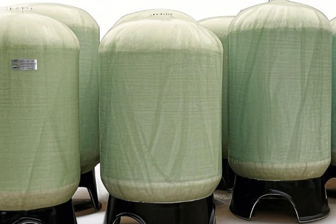
An FRP tank can be perfectly sound from the outside and carrying a growing delamination two plies in. Visual inspection sees the surface; a Barcol hardness reading sees the resin; a thickness gauge sees the wall. None of them see whether the laminate is quietly failing under load. Acoustic emission does, and that is why it has become the standard acceptance and in-service examination for FRP vessels rather than an exotic option. This guide covers what AE physically detects in a composite, the three governing documents — ASTM E1067, ASME Boiler and Pressure Vessel Code Section V Article 11 and Section X Article RT-6 — the scope limits that decide whether your vessel can be examined this way at all, the sensor and loading procedures that make a test valid, the Felicity ratio and the emission-during-hold criteria that decide pass or fail, and how to write the requirement into a purchase order so the result means something.
1. What Acoustic Emission Actually Detects
A composite under rising load does not fail silently. Resin cracks, fibres debond, fibres pull out, fibres break and plies separate, and every one of those events releases a burst of elastic energy that propagates through the laminate as a stress wave. AE sensors bonded to the surface pick those waves up as hits, and the pattern of hits tells you where damage is growing and how fast.
| Damage mechanism | What it sounds like to an AE system | Engineering significance |
|---|---|---|
| Resin cracking (matrix cracking) | Low to medium amplitude, numerous, spread across the vessel | Early-stage, usually acceptable in moderation, but a rise in rate from one test to the next is the signal that matters |
| Fibre debonding and pull-out | Medium amplitude, clustered near stress concentrations | Load path degrading locally |
| Fibre breakage | High amplitude events, often in bursts | Serious; the load-carrying capacity is being consumed |
| Delamination | Distinct cascades, strongly localised | The classic hidden FRP defect; invisible from the surface and progressing under cyclic pressure |
| Bond failure at nozzles and manways | Clusters at the attachment | Leak or detachment risk at the most heavily stressed discontinuity |
| Leaks through the laminate | Continuous broadband emission from the escaping fluid | Detectable with surface-mounted sensors as well as by pressure decay |
Two of the properties that make AE useful are worth stating plainly. It is a global examination: a modest number of sensors covers the whole vessel, including areas under insulation that would otherwise require removal. And it is a stressed examination: damage that is not being loaded does not emit. A flaw in a low-stress region, or one that is structurally insignificant, will simply produce no signal — which is a feature when you are trying to find the defects that matter, and a limitation when you are trying to find every defect that exists.
AE does not tell you what a defect is. It tells you, with location, which defects are active under load — and those are the ones that will decide the vessel's remaining life.
2. The Three Documents That Govern an FRP Vessel AE Test
The technical lineage here is worth knowing because tender documents frequently cite one and expect another.
| Document | What it covers | When it governs |
|---|---|---|
| ASTM E1067/E1067M | Standard practice for AE examination of FRP tanks and vessels under pressure or vacuum | The default technical procedure; the current edition is E1067/E1067M-25, superseding the 2018 edition. It originated as a recommended practice developed by the reinforced-plastics industry body before being standardised. |
| ASME BPVC Section V, Article 11 | Acoustic emission examination of fibre-reinforced plastic vessels — the code procedure | Whenever the vessel is being built or examined under ASME rules; it is the article the Section X requirements point to for method |
| ASME BPVC Section X, Article RT-6 | The mandatory AE test for one-of-a-kind FRP pressure vessels, with the code's own evaluation criteria | Section X Class I vessels where design qualification is by prototype testing rather than calculation |
| ASTM E1118 | AE examination of reinforced thermosetting resin pipe | Piping rather than vessels, but the same physics and often the same programme |
| ASTM E1211 and E569 | Leak detection and location with surface-mounted sensors; AE monitoring during controlled stimulation | Leak location, and structural monitoring where a full pressure cycle is not possible |
| ASTM E1316 | Terminology for non-destructive examinations | The definitions your procedure must use, so that hit, signal strength and MARSE mean the same thing to everyone in the room |
| ASME STP-PT-023 | Guidelines for in-service inspection of composite pressure vessels | Building an inspection programme around AE rather than a one-off test |
One clarification that matters for cost. Section X Class I vessels are design-qualified by destructive testing of a prototype — repeated pressure cycling up to the design pressure, then proof pressure well above it — and no design calculations are required. Class II vessels are designed by calculation, and every Section X Class II vessel must also pass an acoustic emission examination before it can receive a code stamp. So AE is not an optional extra on a Class II vessel; it is the experimental verification that the calculated design works in the as-built laminate.
3. Scope Limits: Can Your Vessel Be Examined This Way at All
ASTM E1067 is deliberately bounded. If your equipment sits outside these limits, the practice is not applicable and a proposal that does not say so is incomplete.
| Parameter | Limit | Reason it matters |
|---|---|---|
| Internal design pressure | Not greater than 1.73 MPa absolute (17.3 bar, 250 psia) above the static head of the contents | Sets the pressure range over which the response has been characterised |
| Vacuum service | Differential pressure between 0 and 0.10 MPa (0 to 1 bar) | Vacuum vessels are loaded the other way round and need a different loading programme |
| Glass content | Greater than 15 % by weight | Below that the laminate is resin-rich and does not generate usable AE signal strength |
| Equipment condition | New and in-service, including repaired vessels | Post-repair testing is a recognised application |
| Temperature | Conducted below the glass transition temperature of the resin | AE response changes as a composite approaches its Tg |
The pressure ceiling is well above most chemical storage and process service, so the limit rarely bites in practice. Where it does bite is on high-pressure FRP vessels such as reverse-osmosis housings and some oilfield equipment, which sit outside the standard's pressure envelope and need a bespoke procedure agreed in advance.
4. Instrumentation: Sensor Choice, Spacing and the Attenuation Survey
The validity of an AE test rests on sensor layout, and the layout rests on a measurement that is often skipped because it costs time.
- Frequency range. High-frequency sensors in the 100–200 kHz band are the primary choice for defect identification and evaluation. Low-frequency sensors in the 20–80 kHz band may be used for overall monitoring of very large vessels, where the extra sensitivity to distant events is worth the loss of localisation quality.
- Attenuation survey. Signal propagation across the vessel surface is measured with a pencil-lead fracture source — the standard Hsu-Nielsen 0.3 mm 2H lead break — at increasing distances along each path. You need this before you can choose a spacing, because the attenuation on a hand lay-up surface is nothing like the attenuation on a smooth filament-wound shell.
- Spacing rule. Sensor spacing should not exceed three times the distance at which the calibration signal falls to the detection threshold. On a rough or heavily built-up surface that distance can be short, and the sensor count rises quickly.
- Placement logic. Prioritise high-stress zones, geometric discontinuities, nozzle and manway attachments, and known repair areas. Uniform coverage is not the goal; coverage of the places that fail is.
- Instrument capability. The system must record hits, signal strength and duration in real time, and must be able to locate sources in real time. Signal strength — the area under the rectified signal envelope, called MARSE in the ASME code — is the workhorse parameter. A bar chart of cumulative signal strength per channel and an amplitude-versus-time display are not conveniences; they are how the operator sees a growing defect during the test.
- Environmental performance. Sensitivity variation across the working temperature range should be within about 3 dB, and the sensors should be omnidirectional to within about 4 dB, with effective screening against radio-frequency and electromagnetic interference. A test run next to a large motor or an arc-welding set without screening produces noise, not data.
5. Preparing the Vessel: Why Preconditioning Is Not Optional
A vessel that has already been stressed carries the memory of that stress. The Kaiser effect means a laminate reloaded to a previously experienced load stays acoustically quiet until that previous maximum is approached, and only then starts emitting again. That property is what makes AE such a clean detector of new damage — but it also means that an in-service vessel tested for the first time produces a misleadingly quiet result.
The practice addresses this directly with a decompression preconditioning step for previously stressed vessels. The vessel is held at reduced pressure for a period set by how far the pressure is being reduced, ranging from around twelve hours to as long as seven days. Skipping or shortening that step is the single most common way to obtain a clean test on a vessel that is not clean.
Two further preparation points. The previous maximum load for the purpose of the Felicity ratio is the highest load the vessel has ever seen — including any earlier hydrotest or overpressure event, not just the last AE examination. And the loading medium matters: water is the preferred medium for pressure vessels and process liquid for atmospheric tanks, because both are efficient acoustic couplers compared with a gas.
6. The Loading Procedure by Vessel Type
Each class of vessel gets its own loading programme, and each has a defined hold at the end during which the meaningful data is collected.
| Vessel type | Loading medium | Loading programme | Final hold |
|---|---|---|---|
| Atmospheric pressure vessel | Process liquid preferred | Graded filling to the maximum operating level | Defined hold at full level |
| Pressure vessel | Water preferred | Pressurisation, hold, depressurisation cycle — typically taken up in steps to the test pressure and back | 30 minutes |
| Vacuum vessel | Vacuum pump system | Graded evacuation to the design vacuum | 30 minutes |
The final hold is where the test earns its keep. During a hold at constant load, a sound laminate goes quiet and stays quiet. A laminate with growing damage keeps emitting, because the damage is progressing under a load that is not changing. That is why emission during the hold is treated as a stronger rejection indicator than the Felicity ratio on its own: a ratio can be depressed by events that are not structurally significant, but sustained emission at constant load means something is moving right now.
7. The Acceptance Criteria
Four parameters carry the decision, and they are read together rather than in isolation.
| Parameter | How it is defined | Acceptance reading |
|---|---|---|
| Felicity ratio, FR | Load at onset of significant emission divided by the previous maximum load: FR = Ponset / Pprevious max | At or above 0.95 is the basic requirement for FRP vessels. A ratio at or above 1.0 means the Kaiser effect held and the vessel behaved elastically. |
| Emission during hold | Hit or signal-strength activity while load is held constant | Continuing emission indicates damage still growing. Treated as a primary rejection indicator. |
| High-amplitude events | Individual hits above a procedure-defined amplitude | Generally associated with fibre breakage and significant structural damage; count and location both matter |
| Source location density | Concentration of located events in a zone | Clusters at nozzles, manways and repairs are the highest-priority follow-up targets |
8. Reading a Felicity Ratio Correctly
The Felicity ratio looks like a simple division, and it is the most misused number in the whole method. Three points decide whether a ratio is trustworthy.
- "Significant emission" must be defined in the written procedure. Codes define it explicitly — as a hit rate, a count rate or an amplitude crossing sustained over a defined load increment. If the definition is not written down, two operators will read two different onset loads off the same plot, and results between vessels in a programme become incomparable.
- The onset load is read off the plot, not judged by ear. Plot cumulative emission against load; the onset is where the curve breaks upward. Subjective reading is how a failing vessel gets a passing ratio.
- The previous maximum must include every prior loading. A vessel that was hydrotested to a pressure above its normal operating pressure carries that hydrotest as its previous maximum. Using the operating pressure instead produces a ratio that flatters the vessel.
A ratio below the acceptance threshold is a rejection or a re-evaluation trigger, not an automatic scrapping decision. The correct next step is follow-up by a complementary method at the located source — visual examination, ultrasonic testing, dye penetrant, or internal inspection — to establish what the active source actually is. AE tells you where to look; it does not tell you what you will find.
9. Where AE Fits in an Inspection Programme
AE works best as the first screen in a tiered programme rather than as a standalone test.
| Method | What it finds | Coverage | Production impact |
|---|---|---|---|
| Visual and dimensional inspection | Surface cracking, crazing, discolouration, weepage, deformation, connection condition | External and internal surfaces only | Requires access; internal work requires entry and cleaning |
| Barcol hardness and thickness survey | Resin cure state, local thickness variation | Point measurements | Low, but sampling is sparse |
| Acoustic emission | Active damage under load, located | Global, through insulation | Minimal; often run on-line at operating stress |
| Ultrasonic / dye penetrant / internal inspection | Definition of a specific indication | Local, targeted | Higher, done only where AE points |
The cost argument follows from that structure. A full internal inspection means draining, cleaning, entry, and confined-space procedures, and it still only covers what the inspector can see and reach. An AE screen covers the whole vessel without interruption, and internal entry becomes necessary only if AE finds an active source that needs to be seen from the inside. On a large vessel in continuous service, that inversion of the workflow is the whole business case.
10. What AE Cannot Tell You
A specification that over-promises on AE will end in a dispute, so the limitations should be written down as clearly as the capabilities.
- It cannot find inert defects. Delamination that is not loaded, or a flaw in a low-stress zone, produces no emission and therefore no indication. A clean AE test is not a statement that the laminate is free of defects.
- It cannot measure remaining strength. AE indicates activity, not margin. A vessel with no emission at test pressure has demonstrated that it is quiet at that pressure, not that it has a quantified margin beyond it.
- It is sensitive to mechanical and process noise. Pumps, agitators, valves, flowing product and rain on a steel roof all generate hits. Background noise measurement before the test, and an agreed noise threshold, are part of a competent procedure.
- It needs a documented, repeatable route. A ratio from a test with one sensor layout cannot be compared with a ratio from a test with another. Fix the sensor map, the loading programme and the emission definition, and reuse them for the life of the vessel.
- It does not cover thermoplastic-lined and dual-laminate vessels in the same way. Where a non-bonded thermoplastic liner sits behind the structural laminate, the AE response comes from the load-bearing composite, and the liner's own condition has to be assessed separately.
11. Writing the AE Requirement Into a Purchase Order
If AE is required, it should be a line item in the order, not an inspection note. What to state:
- The governing practice and edition — for example ASTM E1067/E1067M-25 — plus the code article if the vessel carries or is intended to carry a code stamp.
- The loading programme, the medium, the test pressure or vacuum level, and the hold duration.
- The preconditioning requirement for in-service vessels, including the decompression hold period.
- The definition of significant emission, and the acceptance threshold, expressed numerically.
- The sensor layout, or the requirement to submit one for approval along with the attenuation survey results.
- The reporting content: located source list, amplitude distribution, Felicity ratio calculation with the plot, emission-during-hold assessment, and a clear pass, fail or re-evaluate conclusion.
- The performance requirement on the examination body — accreditation for the method and a written procedure issued before the test.
- The follow-up obligation: which complementary technique will be used to examine located indications, and who pays for repairs if the indication proves to be a defect.
12. Specification Checklist for FRP Vessels and Tanks
- Confirm the vessel is inside the scope of the practice — pressure, vacuum, glass content and temperature.
- Confirm whether the code route is design-by-calculation with mandatory AE, or design-by-prototype with the code's own AE evaluation criteria.
- Fix the emission definition before the test, not after the results are in.
- Record the previous maximum load as the highest ever applied, including hydrotests and overpressure events.
- Require the attenuation survey and the sensor map as deliverables.
- Require background noise measurement and an agreed noise threshold.
- Treat emission during hold as a first-class criterion alongside the Felicity ratio.
- Require located sources to be examined by a second method rather than simply reported.
- Keep the sensor map and loading programme for the next test, so ratios are comparable over the vessel's life.
A Quiet Vessel Is the Only Test Result That Means Anything
Acoustic emission is unusual among non-destructive methods in that the most valuable result is the absence of a signal. A vessel that goes quiet during the hold, with a Felicity ratio at or above the threshold and no high-amplitude clusters at its nozzles, has demonstrated something that no surface inspection can: that under real load, nothing inside it is moving. Getting that result depends on a valid procedure — correct sensor spacing, measured attenuation, adequate preconditioning and a written definition of significant emission. If you are specifying FRP storage tanks or vessels that need to be examined this way, send us the design pressure, contents, glass content and service history, and our engineers will confirm the applicable practice and the test programme that goes with the laminate.
Related reading: our filament-wound FRP storage tanks and FRP chemical and acid storage tanks, FRP grating and handrail condition assessment for the walkway side of an inspection programme, FRP tank repair and relining for what happens after an indication is confirmed, FRP vessels to ASME Section X and RTP-1 for the code-selection context, gel coat and corrosion barrier liner design and FRP storage tank transport and installation.
Need help selecting FRP products?
Our engineers answer technical questions free of charge.
Ask an Engineer on WhatsApp